-
Whatsapp: +86 13526572721
-
Email: info@zydiamondtools.com
-
Address: AUX Industrial Park, Zhengzhou City, Henan Province, China
-
Whatsapp: +86 13526572721
-
Email: info@zydiamondtools.com
-
Address: AUX Industrial Park, Zhengzhou City, Henan Province, China

What is Built-Up Edge (BUE) and How Can You Prevent It?
What exactly is a Built-Up Edge (BUE) in machining, and what actionable steps can you take to stop it from ruining your parts?
A Built-Up Edge (BUE)1 is the unwanted accumulation of work-hardened workpiece material that pressure-welds to the cutting tool’s rake face due to extreme friction and heat. You can prevent BUE by optimizing your cutting parameters, selecting high positive rake angles, applying high-pressure coolant, and upgrading to advanced tool materials like PCD or Cermet.
The Core Mechanisms Behind BUE Formation
What exactly causes a Built-Up Edge to form during the machining process?
Built-Up Edge (BUE) forms when extreme friction and high temperatures cause thin layers of workpiece material to adhere to the tool’s cutting face. Subsequently, successive layers accumulate on top of this initial layer. This creates a highly work-hardened mass that temporarily acts as the new cutting edge before eventually breaking away.
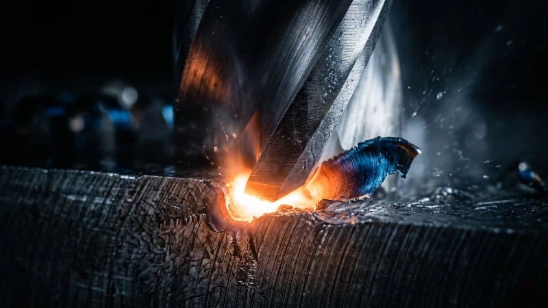
Friction and Extreme Cutting Temperatures
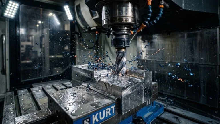
When a cutting tool shears metal, it generates massive amounts of mechanical energy. Consequently, over 90% of this mechanical energy transforms directly into heat. As the metal chip separates from the workpiece, it must slide across the tool’s rake face. This continuous sliding action creates intense friction.
Because the newly formed chip is under immense pressure, it does not slide smoothly. Instead, the bottom surface of the chip rubs violently against the tool. Therefore, the temperature at the tool-chip interface skyrockets. During heavy roughing operations, these localized temperatures can easily reach between 500°C and 1000°C.
Is the tool absorbing all of this heat? Usually, a properly flowing chip carries away most of the thermal energy. However, under specific conditions, the heat stays trapped exactly at the cutting edge.
Think of this process like using a badly loaded abrasive wheel on a surface grinder. Instead of cleanly shearing the metal, the dull wheel forcefully rubs against the workpiece. Ultimately, this friction rapidly overheats the contact area. Similarly, high friction on an insert traps heat right where the cutting action happens.
The Pressure Welding Phenomenon
Once the extreme heat softens the bottom layer of the chip, the metal becomes highly plasticized. Next, the immense cutting force pushes this softened, sticky metal firmly against the insert. This specific combination of high heat and high pressure triggers a solid-state bond. In machining, we call this the “pressure welding phenomenon.”
This bonding mechanism is remarkably similar to rotary friction welding2. In friction welding, a lathe chuck spins one metal rod against a stationary rod under high pressure. The resulting friction heats the metals, and the pressure welds them together solidly without actually melting them into a liquid state.
Similarly, the hot workpiece material micro-welds itself directly to the tungsten carbide matrix3 of the cutting tool. Furthermore, this is not a one-time event. The pressure welding happens in a continuous, destructive cycle:
- Adhesion: The first thin layer of material welds permanently to the rake face.
- Accumulation: New layers of hot chips weld directly on top of the first layer.
- Hardening: This piled-up metal undergoes severe strain hardening4. Consequently, it becomes much harder than the original workpiece material.
- Fracture: Eventually, the built-up mass grows too large. The cutting forces forcefully rip it off.
To clearly understand this shift in the cutting environment, review the comparison below:
| Cutting State | Chip Flow Dynamics | Interface Temperature | Tool Surface Condition |
|---|---|---|---|
| Normal Cutting | Slides smoothly away | Stable and controlled | Clean rake face |
| BUE Formation | Stagnates and sticks | Exceeds yield point | Welded material layers |
Ultimately, when the hardened BUE breaks off, it does not leave cleanly. It often tears microscopic chunks of the tool’s surface with it, setting the stage for rapid tool failure.
Common Symptoms Identifying BUE During Machining
How can you tell if a built-up edge is secretly ruining your machining process before the part is completely scrapped?
You can identify a Built-Up Edge (BUE) by observing three primary symptoms during the machining cycle: a sudden and severe degradation in the workpiece’s surface finish, unexplained dimensional inaccuracies that drift out of tolerance, and rapid or unpredictable tool wear such as edge chipping.
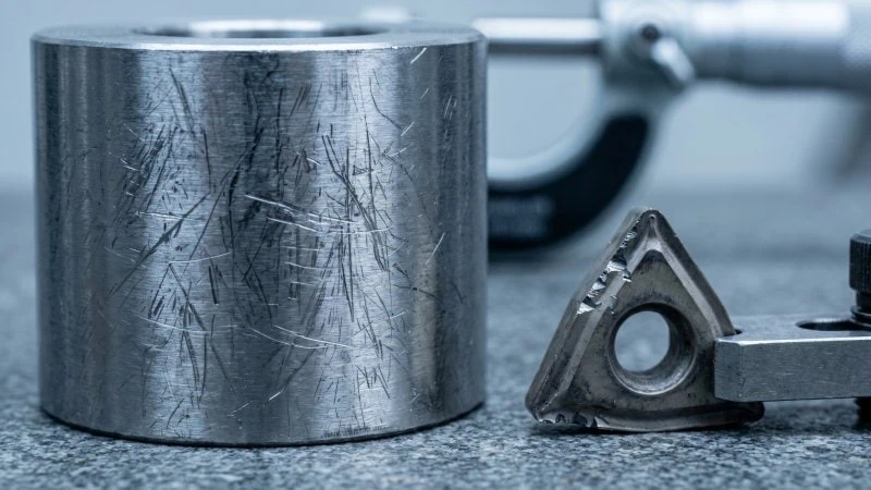
Sudden Degradation of Surface Finish
Have you noticed a shiny, clean part suddenly turning dull and cloudy? This is usually the first major red flag. As the built-up material grows on the insert, it becomes highly unstable. Eventually, the sheer cutting force rips this hardened lump away.
Consequently, fragments of this extremely hard material get dragged right across the freshly machined surface. This dragging action leaves deep, irregular scratch marks and a torn appearance. It is very similar to a glazed grinding wheel chattering across a workpiece instead of cutting cleanly.
Therefore, your surface roughness averages (Ra)5 will spike immediately. For instance, a targeted Ra 1.6 µm finish might instantly degrade to a rough Ra 6.3 µm finish. If your normally smooth turning passes suddenly look like they were cut with a coarse file, a BUE is likely the culprit.
Unexpected Dimensional Inaccuracies
Why do your perfectly dialed-in machine offsets suddenly produce undersized or oversized parts? A built-up edge physically alters your tool’s actual cutting geometry. When material welds to the rake face, it essentially creates a false cutting edge.
Consequently, this lump protrudes further than your programmed tool path. This means your effective depth of cut is now deeper than intended. For example, a severe BUE can easily add 0.05 mm to 0.15 mm to the tool tip’s radius.
Therefore, a CNC lathe programmed to turn a precise 50.00 mm shaft might suddenly yield a 49.80 mm shaft. This artificial offset fluctuates continuously because the lump breaks off and rebuilds repeatedly. Consequently, maintaining tight tolerances becomes mathematically impossible. This shifting baseline is much like thermal expansion causing axis drift in a ball screw, but it happens directly at the cutting edge.
Rapid or Abnormal Tool Wear
Is your carbide insert chipping long before its expected tool life ends? BUE is incredibly destructive to the cutting tool itself. As previously established, the workpiece material pressure-welds directly to the insert.
Strikingly, this weld is often stronger than the carbide substrate itself. Therefore, when the hardened lump finally breaks away, it does not leave quietly. Instead, it literally tears microscopic chunks of carbide and coating away with it. We call this phenomenon micro-chipping or coating delamination.
Over a few minutes, this repetitive tearing cycle destroys the cutting edge completely.
To help you diagnose these issues quickly on the shop floor, review this symptom breakdown:
| Machining Symptom | Direct Cause from BUE | Immediate Result |
|---|---|---|
| Cloudy Surface Finish | Hardened fragments dragging across the part | Spikes in Ra roughness values |
| Tolerance Shifting | False cutting edge altering the tool geometry | Unpredictable part dimensions |
| Micro-Chipping | Welded material tearing the carbide substrate | Premature and sudden tool failure |
Materials Most Susceptible to Edge Build Up
Which specific metals are most likely to trigger a built-up edge on your cutting tools?
The materials most susceptible to built-up edge formation are soft, highly ductile, and gummy metals. Specifically, non-ferrous alloys like aluminum, along with low-carbon steels, pose the highest risks because their low yield strength allows long, continuous chips to stretch, stick, and pressure-weld directly to the tool face.
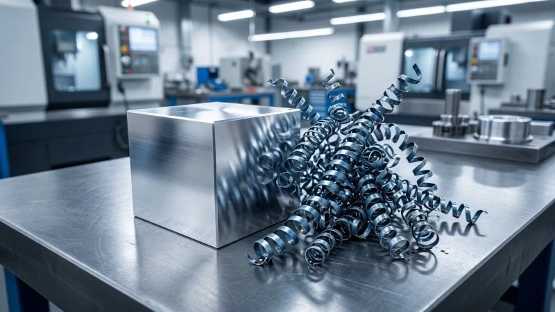
Aluminum and Non-Ferrous Alloys
Are you turning aerospace parts or milling soft extrusion profiles? Aluminum and other non-ferrous metals, like pure copper or soft brass, are notorious for sticking to inserts. Their physical nature makes them highly prone to adhesion.
First, these metals are incredibly ductile. This means they stretch significantly before they finally shear away from the workpiece. Instead of forming a crisp, broken chip, they form long, continuous ribbons. Secondly, they have relatively low melting points. Consequently, the standard heat generated during cutting makes the material extremely sticky very quickly.
Think of this process like trying to broach a deep keyway in a block of pure copper. The soft copper refuses to cut cleanly. Instead, it drags, tears, and heavily packs itself into the teeth of the broach. Similarly, soft aluminum drags and packs heavily onto a lathe insert.
Note: The silicon content in aluminum drastically alters its machinability. For example, a cast 356 aluminum (high silicon6) is highly abrasive, whereas an extruded 6061-T0 aluminum (low silicon) is incredibly gummy and prone to BUE. Always check your material’s specific chemistry before selecting tools.
Low-Carbon Steels
Why do everyday structural steels cause so much trouble on the shop floor? Low-carbon steels, often called mild steels (such as AISI 1018 or A36), contain very little carbon. Usually, the carbon content is below 0.30%. This specific lack of carbon makes the metal very soft.
While softness might sound easy to cut, it actually creates a severely “gummy” cutting environment. Because the metal lacks hardness, it strongly resists clean shearing. Instead of snapping off cleanly, the metal simply tears and smears across the cutting edge.
Consider a common workshop scenario: trying to machine thread a blind hole in a gummy piece of 304 stainless steel with a dull tap and inadequate cutting fluid. The material immediately seizes, packs into the flutes, and cold-welds to the high-speed steel tool, often snapping it. Soft, low-carbon steel behaves exactly like this on your rake face. Because the chips will not break, they continuously rub and generate the exact friction needed to weld onto the tool.
To understand why some metals stick while others do not, review this comparison table:
| Material Grade | Metal Classification | Typical Elongation (Ductility) | BUE Risk Level |
|---|---|---|---|
| Aluminum 1100-O | Soft Non-Ferrous | ~35% | Extremely High |
| AISI 1018 | Low-Carbon Steel | ~15% – 25% | High |
| AISI 4140 | Medium-Carbon Alloy | ~10% – 15% | Low |
Ultimately, materials with high elongation percentages are the most likely offenders. They simply possess too much stretch and flexibility, forcing the material to smear rather than shear.
Proven Machining Strategies to Prevent BUE
When faced with a persistent built-up edge, adjusting your immediate cutting environment is often the fastest way to solve the problem.
You can prevent a Built-Up Edge (BUE) by actively manipulating your cutting parameters, specifically by drastically increasing your cutting speed to break the adhesion cycle, selecting tools with high positive rake angles to reduce friction, and applying targeted, high-pressure coolant directly to the cutting zone to lower temperatures.
Optimizing Cutting Speed for Your Material
Why does running your CNC machine faster actually help prevent material from sticking? It sounds counterintuitive, but speed is often your best defense.
When you increase your cutting speed (measured in Surface Feet per Minute or SFM), you generate a higher shear angle. Consequently, the metal chip becomes significantly thinner. A thinner chip flows much faster across the surface of the insert. Therefore, the hot metal simply does not have enough time to sit there and pressure-weld to the tool face.
Conversely, running your spindle too slowly creates a massive problem. Low speeds produce thick chips and prolonged friction. This creates the perfect “danger zone” for a built-up edge. For example, many machinists completely eliminate BUE by simply increasing their cutting speed from 100 m/min to 250 m/min when using carbide inserts.
Think of this like High-Speed Machining (HSM)7 milling strategies. In HSM, moving the cutter at extremely high feeds and speeds throws the heat entirely into the chip rather than the tool. The chip evacuates so quickly that the heat has no time to transfer to the workpiece or cause adhesion.
Note: Optimal Surface Feet per Minute (SFM) limits depend heavily on machine rigidity and specific carbide grades. Always reference your tooling catalog’s starting parameters to avoid catastrophic tool failure.
Selecting High Positive Rake Angles and Sharp Edges
The physical shape of your cutting tool plays a massive role in stopping metal from welding to it. The answer lies in reducing the overall cutting pressure.
A high positive rake angle directly reduces the amount of force needed to shear the metal. When you use a highly positive insert, the material slices easily. Less cutting pressure immediately equals less friction. As we know, less friction means lower temperatures. Without extreme heat and pressure, a built-up edge cannot form.
Furthermore, you must use an insert with a sharp, ground cutting edge. Many heavy-duty turning inserts feature a heavily honed (rounded) edge to prevent chipping. However, a dull or rounded edge violently plows and crushes the metal rather than slicing it. This plowing action causes extreme heat and guarantees material adhesion.
Consider a parting-off (grooving) operation on a lathe. If the parting insert has a completely flat, neutral geometry, it plows into the material, creating immense chatter, heat, and poor chip evacuation. However, a parting insert with a sharp, positive lead angle cleanly shears the chip, drastically reducing cutting pressure. Your standard turning inserts behave the exact same way.
| Tool Geometry | Cutting Action | Friction Level | BUE Risk |
|---|---|---|---|
| Negative Rake, Honed Edge | Plowing / Crushing | Extremely High | High |
| High Positive Rake, Sharp Edge | Clean Shearing | Very Low | Low |
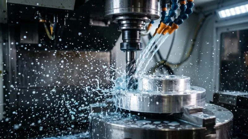
Applying Effective Coolant and Lubrication Strategies
Standard flood coolant often fails during heavy machining. The immense heat at the cutting zone instantly vaporizes the low-pressure coolant. This creates a thermal vapor barrier. Consequently, the fluid never actually reaches the cutting edge where the pressure welding occurs.
To break this barrier, you must use high-pressure coolant. Systems pushing 1,000 PSI or more blast directly into the tool-chip interface. This high-velocity stream accomplishes two things. First, it physically forces the chip away from the rake face, shortening the contact time. Second, it drastically drops the localized temperature below the material’s welding point.
Alternatively, you can utilize Minimum Quantity Lubrication (MQL). MQL delivers a highly precise, atomized mist of concentrated oil. While it provides less cooling than water-based fluids, it offers massive lubricity. This oil coats the tool face and physically prevents the material from sticking.
This is very similar to deep-hole gun drilling. In gun drilling, you cannot rely on gravity to get coolant into a deep bore. You must pump high-pressure cutting oil directly through the tool body. This flushes the chips out instantly and provides extreme lubrication, preventing the chips from packing and welding inside the hole.
Advanced Tooling and Coating Upgrades
When standard parameter adjustments fail, what specific tooling and coating upgrades can permanently eliminate built-up edge problems on your shop floor?
Upgrading to specialized cutting tool materials and advanced surface coatings is the most definitive way to prevent Built-Up Edge (BUE). Specifically, utilizing Polycrystalline Diamond (PCD) tools provides extreme lubricity for non-ferrous materials, while deploying Cermet inserts or specialized physical vapor deposition (PVD) coatings eliminates the chemical affinity that causes low-carbon steels to stick.
Upgrading to PCD Tools for Aluminum and Non-Ferrous Alloys
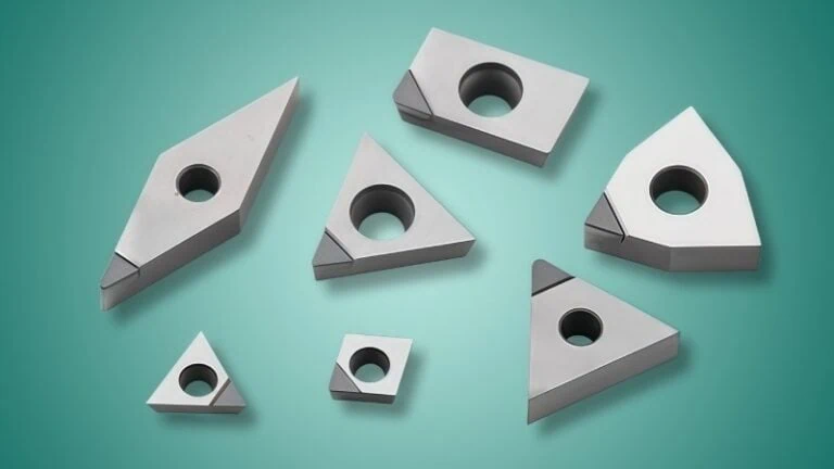
If you run high-volume aluminum parts, standard carbide tools often struggle. You can easily fix this by upgrading to Polycrystalline Diamond (PCD) inserts8. PCD is a highly engineered, synthetic diamond material. It is incredibly hard and exceptionally slick.
The Extreme Low-Friction Advantage
Why does PCD stop soft aluminum from sticking? It all comes down to surface friction. PCD has a friction coefficient that is drastically lower than polished tungsten carbide. Consequently, the hot aluminum chip cannot grip the cutting face. It simply slides away instantly.
Think of this mechanism like a hydrostatic spindle bearing in a high-end CNC grinder. In a hydrostatic spindle, high-pressure oil completely separates the rotating shaft from the housing. Therefore, metal-to-metal contact is impossible, and friction drops to near zero. Similarly, PCD acts as an impenetrable, low-friction barrier against gummy non-ferrous metals.
Furthermore, PCD tools transfer heat incredibly fast. Diamond is one of the best thermal conductors on Earth. As a result, it pulls heat away from the cutting edge immediately. Without trapped heat, the pressure welding phenomenon simply cannot occur.
Note: PCD performance depends heavily on its microscopic grain size (typically ranging from 2 to 25 microns). Finer grains offer better surface finishes, while coarser grains handle abrasive, high-silicon aluminum alloys much better.
To understand the massive difference in performance, review this material comparison:
| Tool Material | Surface Friction Coefficient | Thermal Conductivity | BUE Risk in Aluminum |
|---|---|---|---|
| Uncoated Carbide | High | Moderate | High |
| PCD (Diamond) | Extremely Low | Excellent | Near Zero |
Leveraging Cermet Tools and Anti-Adhesive Coatings for Steels
You absolutely cannot use PCD tools on steel. Iron reacts chemically with carbon-based diamond at high temperatures. Consequently, the diamond literally dissolves into the workpiece. So, how do you upgrade your tooling for gummy low-carbon steels? You must turn to Cermet tools and advanced PVD coatings.
Breaking the Chemical Bond with Cermet
Cermet stands for “Ceramic-Metal.” These inserts use a titanium carbonitride (TiCN) base instead of standard tungsten carbide. This chemical difference is crucial. Standard carbide contains a cobalt binder. Cobalt chemically bonds with soft steel under high cutting pressure. Cermet does not contain this reactive binder.
Because Cermet lacks that chemical affinity, mild steel chips simply will not weld to it. This behaves identically to using ceramic bearing balls in a high-speed CNC spindle. Steel bearing balls can micro-weld to steel races at extreme RPMs due to metal-on-metal friction. However, ceramic balls absolutely cannot weld to steel, ensuring smooth operation. Cermet provides this exact same anti-welding benefit right at your cutting edge.
Applying Anti-Adhesive PVD Coatings
If you must use standard carbide for impact toughness during roughing, you need a physical vapor deposition (PVD)9 coating. Specialized PVD coatings provide a hard, slick barrier.
These coatings successfully isolate the sticky steel chip from the raw carbide substrate. Moreover, high-end tool manufacturers polish these coatings after deposition. This post-coating treatment removes microscopic droplets on the insert’s surface. Ultimately, a perfectly smooth, coated surface leaves the soft chip with absolutely nothing to grab onto.
Conclusion
A Built-Up Edge can severely damage both your workpieces and your cutting tools if left unchecked. By understanding the core mechanisms of friction and pressure welding, you can quickly identify BUE through poor surface finishes, dimensional shifts, and rapid tool wear. Most importantly, you can prevent it by optimizing cutting speeds, selecting sharp and positive rake angles, and using targeted high-pressure coolant. For challenging materials like aluminum and mild steel, upgrading to specialized solutions like PCD or Cermet tools provides the ultimate defense against material adhesion.
If you are looking to upgrade your cutting tools to high-performance PCD solutions, please feel free to contact us.
References
- Built-Up Edge (BUE)1 – Wikipedia article explaining the mechanics and implications of built-up edge formation in machining.
- rotary friction welding2 – Comprehensive overview of friction welding processes where heat and pressure create solid-state bonds.
- tungsten carbide matrix3 – ZYDiamondTools guide explaining the structural and performance differences between PCD and standard carbide tools.
- strain hardening4 – Science and engineering explanation of work hardening, detailing how metal becomes harder through plastic deformation.
- surface roughness averages (Ra)5 – Detailed breakdown of surface finish parameters, specifically how Ra values are measured and interpreted.
- high silicon6 – ZYDiamondTools case study detailing the unique challenges and PCD solutions for machining high-silicon abrasive aluminum alloys.
- High-Speed Machining (HSM)7 – Introduction to the principles of high-speed machining, emphasizing rapid chip evacuation and heat control.
- Polycrystalline Diamond (PCD) inserts8 – ZYDiamondTools product page detailing standard and custom PCD insert solutions for advanced machining.
- physical vapor deposition (PVD)9 – Technical breakdown of the PVD vacuum deposition process used to create hard, thin-film coatings on cutting tools.