-
Whatsapp: +86 13526572721
-
Email: info@zydiamondtools.com
-
Address: AUX Industrial Park, Zhengzhou City, Henan Province, China
-
Whatsapp: +86 13526572721
-
Email: info@zydiamondtools.com
-
Address: AUX Industrial Park, Zhengzhou City, Henan Province, China

Tool Runout Explained: Causes, Effects on Tool Life, and Proven Solutions
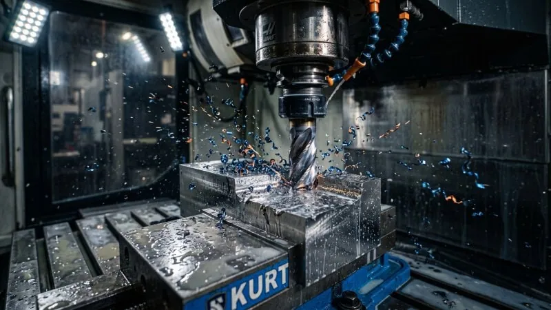
What exactly is tool runout, and how does it impact your CNC machining operations?
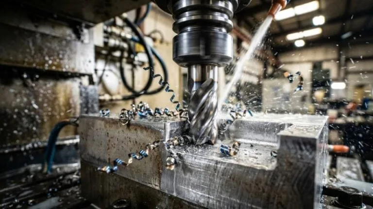
Tool runout is the geometric inaccuracy where a cutting tool rotates off its true central axis, causing uneven cutting forces during operation. This mechanical wobble drastically reduces tool life, compromises surface finishes, and leads to costly dimensional errors in finished parts.
How Excessive Inaccuracy Destroys Your Machining Process
Why exactly does tool runout ruin your machining operations?
Excessive inaccuracy destroys your machining process by shifting the cutting force unevenly across the tool’s flutes. Consequently, this mechanical imbalance directly leads to accelerated tool wear1, sudden micro-tool breakage, poor surface finishes, and parts that fail strict dimensional tolerances.
Premature Tool Wear and Micro-Tool Breakage
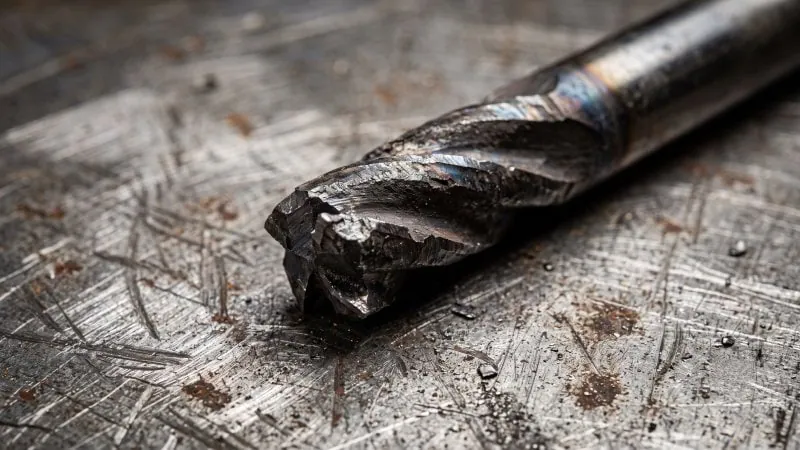
When a cutting tool does not spin perfectly on its axis, it hits the metal with uneven force. Therefore, one side of the tool takes a much heavier hit than the other. This constant pounding wears down the cutting edges much faster than expected.
For standard end mills, runout is a major problem. However, for micro-tools, it is absolutely fatal. In fact, industry data shows that runout must stay below 2% of the tool’s total diameter. If a micro-drill experiences just a tiny wobble, it will snap immediately.
Consider a large multi-tooth face mill. If only one insert takes the entire depth of cut due to an offset, that single insert will chip and fail quickly. The exact same principle applies to a spinning solid carbide end mill.
Interestingly, machining studies show that reducing runout by just 0.0001 inches can increase overall tool life by roughly 10%. Exact tool life parameters will naturally vary based on specific coatings and workpiece materials.
Uneven Chip Load Distribution
What happens when a tool wobbles during a cut? The chip load becomes totally unbalanced. Chip load, or feed per tooth2, is the exact thickness of metal removed by one cutting edge. Ideally, every single flute should remove the exact same amount of material.
Because of runout, the flute pushed furthest outward grabs a massive chip. Meanwhile, the flute on the opposite side barely touches the metal at all. Consequently, the tool pulls and pushes erratically.
| Flute Number | Ideal Chip Load | Chip Load with High Runout | Resulting Damage |
|---|---|---|---|
| Flute 1 | 0.002 inches | 0.0035 inches | Extreme heat, rapid edge chipping |
| Flute 2 | 0.002 inches | 0.0020 inches | Normal expected wear |
| Flute 3 | 0.002 inches | 0.0005 inches | Rubbing, poor cutting action |
| Flute 4 | 0.002 inches | 0.0020 inches | Normal expected wear |
As a result, the overworked flutes overheat and break down. On the other hand, the underworked flutes just rub against the metal. This rubbing creates severe friction and hardens the workpiece material.
Poor Surface Finish and Dimensional Errors
Eventually, the problems caused by runout show up directly on your finished parts. Uneven cutting forces cause the tool to deflect and vibrate. This severe vibration creates harmonic chatter. Chatter leaves distinct, ugly wavy lines across your machined surfaces.
Furthermore, runout completely destroys your dimensional accuracy. For example, if you use a drill with significant radial runout, the drill bit swings in a wider arc than its actual physical size. Consequently, it will definitely cut an oversized, bell-mouthed hole.
Can you afford to scrap expensive aerospace parts because a hole is simply too large? Probably not.
Additionally, the cutting tool pushes away from the workpiece instead of cutting cleanly. This deflection leaves extra, unwanted material behind on the final part. Therefore, your final finishing passes will not meet the required tight tolerances. Ultimately, you will waste valuable time reworking parts or throwing them in the scrap bin.
Common Culprits Behind Spindle and Holder Inaccuracies
What exactly causes a cutting tool to spin off its true center during machining?
Spindle and holder inaccuracies are primarily caused by worn or contaminated tool holders, compromised spindle bearings, and improper setup techniques. Any slight mechanical misalignment in this assembly stacks up, pushing the cutting tool off its true rotational axis and generating significant runout.
Worn or Dirty Collets and Tool Holders
The connection between your machine and your cutting tool must be absolutely perfect. Therefore, dirt is your biggest enemy. Even a microscopic layer of dust will tilt the tool holder.
Think of a standard lathe chuck gripping a long piece of round bar stock. If a single tiny metal chip gets trapped behind one of the chuck jaws, the entire bar will wobble wildly as it spins. The exact same principle applies inside a milling spindle taper3.
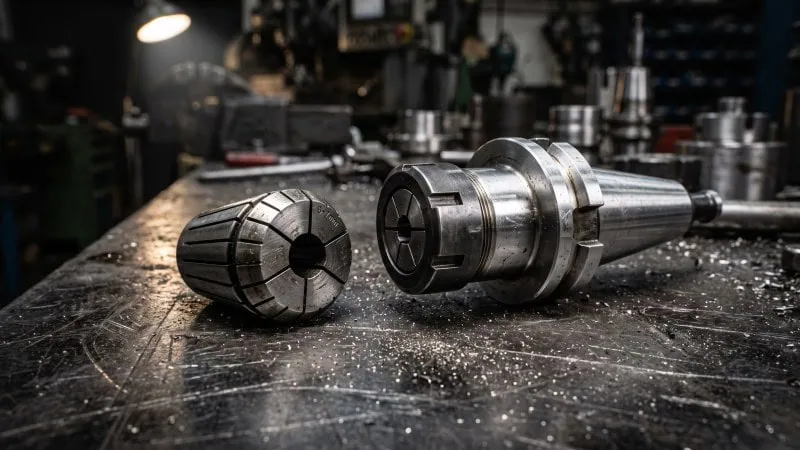
Furthermore, general wear and tear causes significant problems. Over time, metal rubs against metal. Collets lose their elasticity. Tool holder tapers develop small scratches or fretting marks. Consequently, the holder no longer seats perfectly inside the spindle.
Industry experience shows that a tiny 0.0005-inch piece of debris inside a tool holder taper translates to massive runout at the tip of the tool. Because the tool sticks out, this small error multiplies over the tool’s length.
Poor Quality or Damaged Spindles
Sometimes, the tool holder is perfectly fine, but the machine itself is the problem. The spindle is the heart of any CNC machine. If the spindle is flawed, every tool you load will experience runout.
Spindle issues usually stem from two main sources: worn bearings or a damaged taper. Bearings wear out naturally after thousands of hours of high-speed rotation and heavy side loads. When bearings wear down, the spindle shaft gains unwanted play.
Additionally, machine crashes are a major culprit. If an operator accidentally drives a tool into the worktable, the immense force can physically dent the inside of the spindle taper. Once the taper is bent or bell-mouthed, no tool holder will ever sit straight again.
| Spindle Condition | Typical Runout Contribution | Primary Cause |
|---|---|---|
| New or High-Quality | Less than 0.0001 inches | Precision bearings and a clean, flawless taper |
| Worn Bearings | 0.0005 to 0.001 inches | Extended age or constant heavy side loads |
| Crashed Spindle | Greater than 0.001 inches | Physical denting or warping in the taper wall |
Improper Clamping and Setup Errors
Even with perfect equipment, human error frequently causes severe runout. Improper clamping is a very common mistake in machine shops.
For instance, consider the standard ER collet system. Operators often assemble these incorrectly. The collet must snap directly into the collet nut first, before you insert the cutting tool. If you drop the collet into the holder and then screw the nut on top, the collet will crush unevenly. This guarantees a crooked tool.
Over-tightening is another massive issue. Many operators believe that tighter is always better. However, this is completely false.
“Excessive torque twists the collet and distorts the tool holder geometry, instantly introducing runout.”
Using a standard wrench and hitting it with a hammer is a terrible practice. You must use a proper torque wrench. Keep in mind that torque specifications vary greatly based on the specific nut design (such as friction-bearing versus solid nuts), so always verify the exact torque limits with the manufacturer’s specifications before tightening.
How to Accurately Measure Total Indicated Runout
Detecting hidden tool wobble on your shop floor requires specific metrology equipment and a precise procedure.
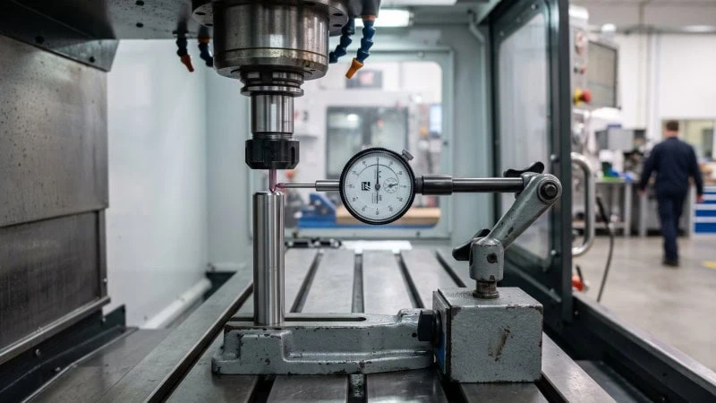
To accurately measure Total Indicated Runout (TIR), mount a high-precision dial test indicator onto a rigid magnetic base directly on the machine table. Next, carefully place the indicator’s stylus against the smooth shank of the clamped cutting tool, rotate the machine spindle slowly by hand, and calculate the exact difference between the highest and lowest needle readings.
Essential Tools for Dial Indicator Setup
Before you can measure anything, you must gather the correct inspection equipment. You cannot rely on your eyes or ears to detect microscopic spindle errors. Therefore, you need high-quality metrology tools.
First, you need a high-precision dial test indicator4. A standard drop indicator is often too bulky for tight machine enclosures. A test indicator features a lever-style stylus that easily reaches the tool shank. For CNC machining, your indicator must read in “tenths” (0.0001 inches) or microns.
Second, you absolutely need a heavy-duty magnetic base. Rigidity is everything in metrology. Just like tramming a milling vise, indicating a tool requires a completely solid foundation. If the magnetic base flexes or shifts even slightly, your measurement is completely useless.
Finally, consider using a ground test pin. Measuring on the fluted cutting edges of an end mill is extremely difficult and inaccurate. Instead, machinists often clamp a perfectly round, precision-ground carbide dowel pin into the tool holder. This smooth surface provides a flawless reading.
| Tool Type | Primary Function | Required Precision |
|---|---|---|
| Dial Test Indicator | Measures the physical deflection | 0.0001 inches (or 0.001 mm) |
| Magnetic Base | Holds the indicator rigid | High magnetic holding force |
| Precision Test Pin | Provides a perfectly round test surface | Grade A (extremely tight tolerance) |
Step-by-Step Measurement Process on the CNC Machine
How do you execute this test safely and accurately? Follow this precise sequence to find your TIR.
Step 1: Clean and load the assembly. First, thoroughly wipe down the spindle taper, the tool holder, and your test pin. Insert the pin into the holder, clamp it properly, and load the entire assembly into the machine spindle.
Step 2: Position the magnetic base. Mount your magnetic base directly onto the cast iron machine table. Make sure the table surface is totally clean so the magnet grips firmly. Reach the indicator arm up toward the spindle.
Step 3: Pre-load the stylus. Carefully jog the machine axes. Bring the tool shank (or test pin) into contact with the indicator’s stylus tip. You want to touch the smooth shank, not the sharp flutes. Push the tool slightly against the stylus to “pre-load” the dial. The needle should move slightly, ensuring constant contact.
Step 4: Rotate the spindle manually. Never turn on the spindle power during this test! Instead, put the machine in neutral. Slowly rotate the spindle by hand for one full 360-degree revolution. Watch the dial carefully.
Step 5: Calculate the final TIR. As you spin the tool, the needle will sweep back and forth. Note the absolute highest positive number. Then, note the absolute lowest negative number.
TIR is simply the total distance traveled by the needle.
For example, if the needle swings to a maximum of +0.0002 inches and a minimum of -0.0001 inches, you just add the absolute values together. Consequently, your Total Indicated Runout is exactly 0.0003 inches.
Proven Strategies to Minimize Deflection and Maximize Tool Life
Eliminating unwanted tool wobble permanently protects your expensive cutting tools and ensures dimensional accuracy.
To minimize deflection and maximize tool life, machine shops must upgrade to high-precision tool holders like shrink-fit or hydraulic chucks. Furthermore, operators must strictly enforce daily cleaning routines for all mating surfaces. Finally, keeping tool overhang as short as mechanically possible directly reduces radial runout and significantly extends tool lifespan.
Upgrading to High-Precision Tool Holders
Standard ER collets are very versatile. However, they rely on multiple moving parts. A standard holder uses a nut, a collapsible collet, and a main body. Every single piece stacks up tiny manufacturing errors. Consequently, these stacked tolerances create runout.
Therefore, upgrading your holding technology is the easiest fix. Hydraulic chucks are a massive upgrade. They use pressurized internal fluid to grip the cutting tool. This fluid pressure applies equal force 360 degrees around the shank. This perfectly centers the tool on the true axis.
Shrink-fit holders5 are even better. These holders have no moving parts at all. The holder features a bore that is slightly smaller than the tool shank. You use an induction machine to heat the metal holder. The heat expands the bore. Next, you drop the cold tool inside. As the holder cools, it grips the tool with immense, perfectly even force.
| Tool Holder Type | Typical Runout (TIR) | Best Use Case |
|---|---|---|
| Standard ER Collet | 0.0003 to 0.0005 inches | General milling and drilling |
| Hydraulic Chuck | 0.0001 to 0.0002 inches | High-precision reaming and finishing |
| Shrink-Fit Holder | Less than 0.0001 inches | High-speed machining and micro-tooling |
When upgrading to these systems, always verify the specific thermal limits and guaranteed TIR values with the tool holder manufacturer.
Implementing Proper Cleaning and Maintenance Routines
How do you keep your high-precision holders perfectly accurate? You must clean them obsessively. A tiny fleck of cast iron dust ruins everything.
Think about inspecting parts on a granite surface plate. Before you place a precision gauge block down, you wipe the granite completely clean. Any dust will tilt the block. You must treat your machine spindle taper the exact same way.
Never just blast the spindle with compressed air. Air simply blows metal chips deeper into the machine bearings. Instead, use a dedicated spindle taper wiper every single shift. These wipers are shaped exactly like your machine’s taper.
Furthermore, you must clean your collets regularly. Remove them from the nuts and scrub them. Many shops use small ultrasonic cleaners to remove baked-on coolant and microscopic fines. If you spot any fretting marks or deep scratches on a holder, throw it away. A damaged $100 tool holder will easily destroy a $20,000 machine spindle over time.
Optimizing Tool Overhang and Cutting Parameters
How far does your cutting tool stick out from the holder? This distance is called tool overhang. Long overhangs amplify runout instantly.
Consider a long boring bar on a CNC lathe. If you extend a boring bar too far out of the turret, it screams and chatters instantly. End mills act the exact same way. Tool deflection6 follows a strict, unforgiving mathematical rule. Deflection increases by the cube of the length.
If you double the stick-out length of an end mill, the tool does not just deflect twice as much. It actually deflects eight times as much. Therefore, you must seat the tool as deeply into the holder as physically possible. Only leave enough flute exposed to safely clear your workpiece.
If you must use a long tool for deep cavity milling, you must adjust your cutting parameters. You cannot run at standard speeds. You must lower your feed rate. Dropping the feed rate reduces the physical cutting force pushing against the tool. Consequently, this prevents the tool from bending away from the cut, saving your surface finish and preventing a catastrophic tool failure.
Conclusion
Controlling tool runout is not just about achieving a better surface finish; it is fundamentally about protecting your investments and maximizing shop floor profitability. Even microscopic deviations at the spindle taper multiply rapidly down the length of the tool, leading to catastrophic tool failure, excessive chatter, and scrapped parts. By understanding the core causes of deflection, regularly measuring TIR with proper metrology equipment, and investing in high-quality tool holders and strict maintenance routines, machinists can effectively eliminate runout. Ultimately, taking the time to secure a perfectly concentric setup guarantees longer tool life, faster cutting speeds, and consistently superior part quality.
References
- Accelerated Tool Wear1 – ZYDiamondTools guide to understanding and troubleshooting premature tooling wear.
- Chip Load, or Feed Per Tooth2 – FM Carbide guide explaining chip load calculations and parameters for machining.
- Spindle Taper3 – Northland Tool article covering the purpose, types, and maintenance of CNC spindle tapers.
- Dial Test Indicator4 – CNCCookbook guide on how to properly set up and use dial test indicators in machining.
- Shrink-Fit Holders5 – HIPPSC resource explaining the mechanism, benefits, and applications of shrink-fit tool holders.
- Tool Deflection6 – Stoney CNC knowledge base article on understanding and minimizing tool deflection in machining.