-
Whatsapp: +86 13526572721
-
Email: info@zydiamondtools.com
-
Address: AUX Industrial Park, Zhengzhou City, Henan Province, China
-
Whatsapp: +86 13526572721
-
Email: info@zydiamondtools.com
-
Address: AUX Industrial Park, Zhengzhou City, Henan Province, China

How to Solve Abrasion and Breakage of PCD and PCBN Cutting Tools in Machining Centers
Are you constantly struggling with premature wear or the sudden, catastrophic failure of your expensive ultra-hard cutting tools during CNC operations?
To effectively solve abrasion and breakage of PCD and PCBN cutting tools1, you must systematically eliminate mechanical instability, incorrect cutting parameters, and thermal shock. This requires maximizing system rigidity by correcting spindle runout and stabilizing workpiece clamping, calibrating surface speeds and feed rates2 to balance heat and impact loads, upgrading tool edge geometry according to the specific tool material, and precisely managing coolant delivery to prevent structural cracking.
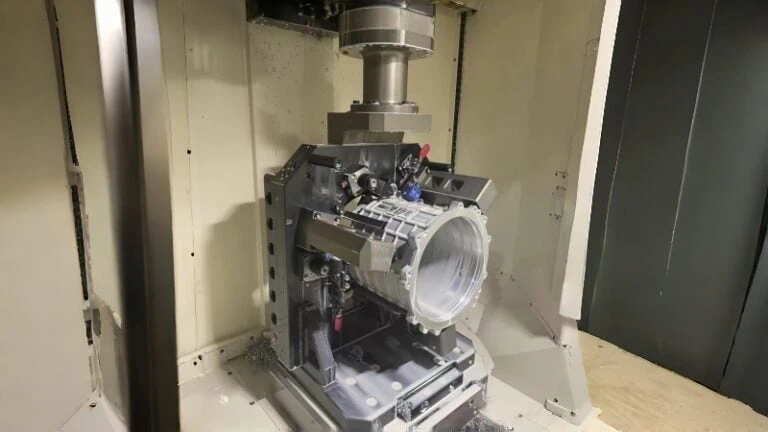
Enhancing Setup and System Rigidity
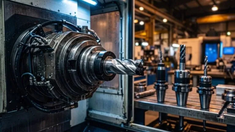
A perfectly rigid machine setup is the absolute foundation for preventing the sudden breakage of ultra-hard cutting tools. Maximizing system rigidity eliminates the harmful micro-vibrations that destroy brittle inserts. Because Polycrystalline Diamond (PCD) and Polycrystalline Cubic Boron Nitride (PCBN) possess extremely low fracture toughness3, any unwanted movement between the tool and the workpiece multiplies the cutting impact forces. Securing the spindle, tool holder, and workpiece creates a stable machining environment that directly stops edge chipping and abnormal abrasion.
Correcting Spindle Runout to Minimize Vibration
Spindle runout4 happens when the tool does not rotate in a perfect concentric circle. This slight wobble creates uneven chip loads. As a result, the cutting edge experiences severe hammering impacts instead of a smooth continuous slicing action.
PCD and PCBN inserts are exceptionally hard but lack the shock-absorbing flexibility of high-speed steel or standard carbide. Think of spindle runout like an unbalanced grinding wheel on a precision surface grinder. Just as the unbalanced wheel bounces, leaves visible chatter marks5 on the workpiece, and eventually damages its own abrasive matrix, a wobbling spindle causes the brittle tool edge to fracture against the metal.
You must measure and correct this runout to save your tools. While a standard roughing end mill might survive 0.015 mm of runout, ultra-hard tools demand much tighter tolerances. Generally, runout for PCD and PCBN applications should be kept strictly under 0.005 mm (5 microns). Always verify the exact maximum allowable runout with your specific machine and tooling supplier, as these tolerances can vary based on the tool grade and holder type.
Upgrading to High-Precision Tool Holders
Standard side-lock (Weldon) holders often push the tool off-center. This instantly creates unacceptable runout. To fix this problem, you should upgrade your holding systems.
- Shrink-Fit Holders: These use thermal expansion to grip the tool shank perfectly on center. They offer massive gripping force and nearly zero runout.
- Hydraulic Chucks: These utilize fluid pressure to clamp the tool evenly. They also provide excellent vibration-dampening properties.
By switching to precision tool holders, you greatly reduce the micro-vibrations that cause premature tool abrasion.
Stabilizing Workpiece Clamping to Reduce Deflection
Even with a perfect spindle, a loose workpiece will destroy an ultra-hard insert. Workpiece deflection occurs when the cutting force pushes the metal away from the tool. When the material snaps back into its original position, it strikes the brittle cutting edge and shatters it.
Consider the mechanics of deep-hole boring. If you use a long, unsupported boring bar, it flexes away from the cut and chatters violently. Similarly, if your workpiece extends too far beyond the chuck jaws without a tailstock, the material bends and vibrates during the machining cycle.
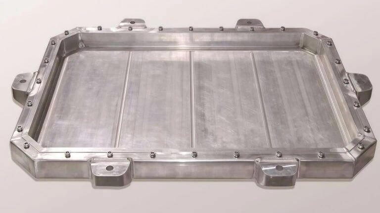
You must support the workpiece as close to the cutting zone as possible. If you are milling a thin-walled aluminum casting with a PCD mill, standard vise jaws might distort the part. Instead, use custom-machined soft jaws that wrap around the part to distribute the clamping pressure evenly.
Common Clamping Issues and Solutions
Here is a breakdown of common fixturing problems that lead to tool breakage, along with practical solutions:
| Fixturing Problem | Resulting Tool Failure | Corrective Action |
|---|---|---|
| Excessive Overhang | Severe chatter and tool breakage due to part bending. | Move the part deeper into the jaws. Use a tailstock or steady rest. |
| Uneven Clamping Force | Part distortion. Tool rubs instead of cutting, causing rapid abrasion. | Implement programmable hydraulic clamping. Use torque wrenches on manual fixtures. |
| Inadequate Jaw Contact | Part slipping during interrupted cuts, shattering the cutting edge. | Machine custom soft jaws to match the exact profile of the workpiece. |
“A rigid setup is the absolute foundation of hard part machining. You cannot fix a vibration problem by changing cutting speeds later; you must eliminate movement at the source.”
Ultimately, checking your clamping pressure and reducing part overhang will drastically improve your tool life. A stable part ensures the cutting edge engages the material smoothly, stopping abrasion and breakage before it starts.

Calibrating Core Cutting Parameters
Correctly adjusting your CNC machine settings is essential to stop expensive ultra-hard inserts from wearing out prematurely or suddenly snapping. Calibrating core cutting parameters prevents tool failure by balancing the mechanical forces and thermal temperatures acting on the cutting edge. You must optimize the surface speed to control the heat zone, adjust the feed rate to reduce chip thickness, and limit the depth of cut to prevent excessive physical stress.
Optimizing Surface Speed for Heat Management
Surface speed (Vc) dictates how hot the cutting zone gets. Consequently, setting the wrong speed directly causes tool failure. PCD and PCBN react completely differently to heat. Therefore, you must manage speed carefully based on the specific material.
PCD tools are primarily used for non-ferrous metals like aluminum. However, PCD cannot handle extreme heat. If the surface speed is too high, the diamond breaks down and turns back into graphite. This process, called graphitization, causes rapid chemical abrasion. Conversely, PCBN tools are used for hard turning. PCBN actually needs high heat to work properly. The high surface speed generates friction, which softens the hardened steel immediately ahead of the cutting edge.
Think of this like friction drilling (thermal part-forming) on a CNC mill. If the friction drill spins too slowly, it catches the sheet metal and snaps. However, spinning at optimal high speeds generates enough localized heat to plasticize the material, allowing the tool to push through smoothly. If your PCBN tool is chipping, your surface speed might actually be too low, not too high.
| Tool Material | Typical Application | Recommended Speed (Vc) | Failure Mode if Speed is Incorrect |
|---|---|---|---|
| PCD | A356 Aluminum | 800 – 3000 m/min | Chemical breakdown (abrasion) if too fast. |
| PCBN | Case Hardened Steel (60 HRC) | 120 – 200 m/min | Edge chipping (breakage) if too slow. |
Because the exact binder composition dictates a tool’s heat resistance, these target speeds can shift. Always verify the specific surface speed limits with your insert supplier before starting the spindle.
Adjusting Feed Rates to Mitigate Impact Loads
The feed rate (f) determines how thick the metal chip will be. If you push the tool too fast, the chip becomes too thick. This massive load instantly snaps a brittle PCBN or PCD edge. Furthermore, pushing too slowly causes the tool to rub against the metal instead of cutting it. This constant rubbing creates massive friction and severe abrasion wear.
Balancing Chip Load for Tool Survival
To prevent breakage, you must balance the feed rate perfectly. This is very similar to broaching a tight keyway in a steel gear hub. If you force the broach too aggressively into the bore, you overload the teeth and shear them off. However, a controlled, steady push peels away clean ribbons of metal without overloading the tool.
When facing an interrupted cut, you must adjust your feed rate. For example, when turning a transmission shaft that has a drilled cross-hole, the tool hits empty space and then crashes back into solid steel. This hammering effect will shatter the insert. By lowering the feed rate by 30% to 50% just as the tool crosses the interruption, you drastically reduce the impact force.
Controlling Depth of Cut in Interrupted Operations
The depth of cut (ap) controls how much of the tool’s edge touches the metal. Taking a very deep cut puts massive mechanical pressure on the insert. Ultimately, this leads to sudden breakage.
When machining parts with interruptions, such as milling across deep splines, depth control becomes critical. You should avoid forcing the tool through a heavy, single pass. Instead, taking multiple shallow passes prevents the cutting edge from absorbing fatal shockwaves.
Moreover, you must ensure your depth of cut is deeper than the work-hardened surface skin left by previous operations. If your depth of cut is too shallow, the tool just scrapes the hardened, abrasive scale of the metal. This scraping action destroys the insert through extreme abrasion. Therefore, maintaining a consistent depth of cut keeps the tool engaged in the softer, uniform metal underneath the surface skin, extending its life significantly.

Upgrading Tool Edge Geometry
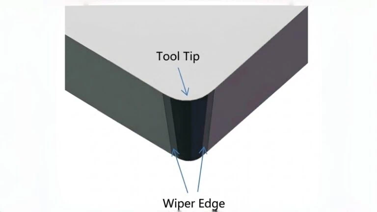
Modifying the microscopic shape of your tool’s cutting edge reinforces the weakest point of the insert against massive cutting forces. By deliberately altering the sharp edge through chamfering or honing, you redirect mechanical stress into the thicker, stronger body of the tool. This intentional geometry modification eliminates fragile micro-peaks on the cutting line, fundamentally preventing both sudden breakage and rapid abrasive wear.
Applying Negative Chamfers for Edge Strength
A perfectly sharp cutting edge is incredibly fragile. When you machine tough materials, a sharp PCBN edge easily snaps under the pressure. To prevent this breakage, manufacturers apply a negative chamfer. This feature is also commonly known as a T-land.
A negative chamfer is a flat, angled surface ground directly onto the cutting edge. Instead of a razor-sharp point hitting the metal, a reinforced, blunt face takes the impact. This design directs the cutting forces straight down into the solid body of the insert. Consequently, the tool can handle much heavier loads without chipping.
Consider the mechanics of a heavy-duty punch press stamping thick steel plate. If the punch die has a razor-sharp corner, that corner instantly chips under the heavy tonnage. However, if you grind a slight bevel onto the punch, the impact load spreads out evenly. The die then survives thousands of hits without damage. A negative chamfer does exactly the same thing for your cutting tools.
When machining case-hardened steel (around 60 HRC), you absolutely need this edge strength. A typical PCBN insert might use a 20-degree chamfer that is 0.1 mm wide. Because these specific dimensions can vary based on your exact workpiece material and hardness, always verify the ideal chamfer angle and width with your tooling supplier before starting your machine.
Utilizing Edge Honing to Prevent Micro-Chipping
Have you ever noticed your PCD or PCBN tool developing tiny, jagged cracks right before it completely fails? This frustrating issue is called micro-chipping. It happens because the extreme tip of the cutting tool is too thin and fragile to absorb cutting heat and mechanical shock.
When your tools are chipping, the sharp edge is failing. To stop this, you must utilize edge honing. Honing is the process of putting a microscopic radius, or round curve6, onto the cutting edge. This removes the microscopic flaws left by the grinding wheel and leaves a reinforced, uniform edge that resists flaking.
However, because PCD and PCBN cut entirely different materials, you must apply the correct scale of honing to avoid destroying the tool in a different way.
For PCBN tools cutting hardened steel, the impact forces are massive. Therefore, PCBN requires a heavier standard hone (typically a 15 to 25-micron radius) to survive.
Conversely, PCD tools are typically kept razor-sharp to cleanly shear aluminum and composites7. But when an up-sharp PCD tool begins to chip during interrupted cuts or when machining abrasive materials (like high-silicon aluminum), you must upgrade to a PCD Micro-Hone. A micro-hone is incredibly small—usually only 2 to 5 microns. This provides just enough structural strength to stop the micro-chipping, without dulling the tool so much that it causes aluminum to melt and stick to the edge (Built-Up Edge (BUE)8).
Choosing the Right Edge Preparation to Stop Breakage
You must match the edge preparation strictly to the tool material and your specific wear issue.
| Edge Preparation | Shape Description | Primary Benefit | Best Application for Troubleshooting |
|---|---|---|---|
| Up-Sharp (Un-honed) | 0 mm radius. Razor sharp. | Standard starting point. Prevents Built-Up Edge (BUE). | General PCD machining where chipping is not an issue. |
| PCD Micro-Hone | Microscopic curve (2-5 microns). | Stops PCD micro-chipping while maintaining shearing ability. | PCD machining abrasive aluminum or facing interrupted cuts. |
| PCBN Standard Hone | Rounded curve (15-25 microns). | Stops PCBN shattering; strengthens the edge for hard impact. | General smooth turning of hardened steel or cast iron. |
| Chamfered Edge | Flat, angled bevel (T-land). | Maximum structural strength against heavy impact. | PCBN facing severe interrupted cutting in case-hardened steel. |

Managing Coolant and Thermal Dynamics
Managing coolant and thermal dynamics prevents catastrophic tool failure caused by rapid heating and cooling. Ultra-hard tool materials expand when hot and shrink when cold, meaning uneven cooling causes sudden structural cracking. By controlling fluid application during interrupted cuts and using high-pressure systems to pierce the vapor barrier, you stabilize the cutting temperature. This consistent thermal control directly stops thermal cracking and drastically reduces abrasive tool wear.
Avoiding Thermal Shock in Discontinuous Cutting
Discontinuous cutting happens when your tool constantly enters and exits the metal. For example, milling across a flat surface with empty gaps, or turning a cylinder that has a milled flat. During these operations, the cutting edge heats up instantly while slicing the metal. Then, it cools down rapidly as it spins through the open air. This extreme hot-and-cold cycle creates thermal fatigue9. Eventually, tiny thermal cracks form on the edge, leading to sudden breakage.
Think of the metallurgical process of heat-treating a raw steel component. If you pull a glowing red part from the furnace and plunge it unevenly into a cold quench, the severe thermal gradient causes the steel to warp and crack instantly. The exact same physical reaction destroys a PCBN insert when standard liquid coolant haphazardly splashes against its blazing hot cutting edge.
To solve this, you must control the environment. For PCBN tools cutting hardened steel, the best method to avoid thermal shock is often running completely dry. Dry machining removes the cold liquid from the equation. As a result, the tool experiences a much gentler temperature shift between the cut and the air.
Conversely, PCD tools degrade chemically if they get too hot. Therefore, if you are machining aluminum with PCD, you cannot run dry. Instead, you must surround the tool with a massive, uninterrupted volume of coolant. This constant flow ensures the tool never overheats in the first place.
Implementing High-Pressure Coolant Delivery Effectively
When machining at high speeds, standard flood coolant often fails completely. As the cutting edge shears the metal, it generates intense heat. When the low-pressure coolant hits this extreme heat, it boils instantly. This boiling action creates a microscopic steam bubble, or vapor barrier, around the tool tip. Consequently, the liquid coolant just bounces off the steam shield and never actually touches the cutting edge. The tool overheats and suffers rapid abrasion.
You must break this vapor barrier to cool the tool properly. Implementing a High-Pressure Coolant (HPC) system solves this problem. HPC systems blast cutting fluid at extreme velocities directly at the cutting zone.
| Coolant Delivery Method | Pressure Range | Action at the Cutting Zone | Impact on Tool Life |
|---|---|---|---|
| Standard Flood Coolant | 10 to 40 PSI | Bounces off the vapor barrier. | High heat causes rapid abrasion. |
| High-Pressure Coolant (HPC) | 1,000+ PSI (70+ bar) | Pierces the steam bubble instantly. | Cools edge directly, stopping wear. |
Furthermore, high-pressure systems physically blast metal chips away from the cutting zone. If metal chips fall back into the cutting path, the tool will crush them against the workpiece. This “re-cutting” action acts like sandpaper, destroying the PCD or PCBN surface through severe abrasion. HPC completely eliminates chip re-cutting.
“Effective cooling is not about how much fluid you pump into the machine; it is entirely about where and how hard that fluid strikes the cutting edge.”
By directing a high-pressure stream exactly between the chip and the tool face, you keep the ultra-hard insert structurally stable and free from abrasive recutting damage.
Conclusion
Mastering the use of Polycrystalline Diamond (PCD) and Polycrystalline Cubic Boron Nitride (PCBN) tools requires a systematic approach to your machining environment. By eliminating micro-vibrations through a rigid setup, precisely calibrating your cutting parameters, selecting the strictly correct edge geometry for your specific material, and carefully controlling thermal dynamics, you can drastically extend tool life. Implementing these strategies will stop sudden tool breakage, minimize abrasive wear, and ultimately improve the efficiency and profitability of your machining operations.
If you need help implementing these solutions or finding the right tools for your specific application, please contact us for expert guidance.
References
- PCD and PCBN Cutting Tools1 – ZYDiamondTools product category offering advanced Polycrystalline Diamond and Cubic Boron Nitride solutions.
- Surface Speeds and Feed Rates2 – ZYDiamondTools calculator for optimizing machining parameters and ensuring tool efficiency.
- Fracture Toughness3 – Wikipedia article detailing the concept of fracture toughness and structural mechanics in materials science.
- Spindle Runout4 – Wikipedia explanation of run-out parameters and their mechanical implications in rotating systems.
- Chatter Marks5 – Wikipedia page explaining machining vibrations, chatter formation, and its effects on surface finish.
- Microscopic Radius, or Round Curve6 – ZYDiamondTools blog post detailing edge radiusing (honing) and its importance in heavy-duty machining.
- Shear Aluminum and Composites7 – ZYDiamondTools guide to achieving optimal surface finishes and higher performance when machining aluminum with PCD tools.
- Built-Up Edge (BUE)8 – Wikipedia article explaining the formation, causes, and effects of a built-up edge during machining operations.
- Thermal Fatigue9 – Wikipedia topic page explaining thermal shock, thermal fatigue, and material expansion cycles.