-
Whatsapp: +86 13526572721
-
Email: info@zydiamondtools.com
-
Address: AUX Industrial Park, Zhengzhou City, Henan Province, China
-
Whatsapp: +86 13526572721
-
Email: info@zydiamondtools.com
-
Address: AUX Industrial Park, Zhengzhou City, Henan Province, China

Battery Tray Manufacturing: PCD Milling Strategies for Extruded Aluminum
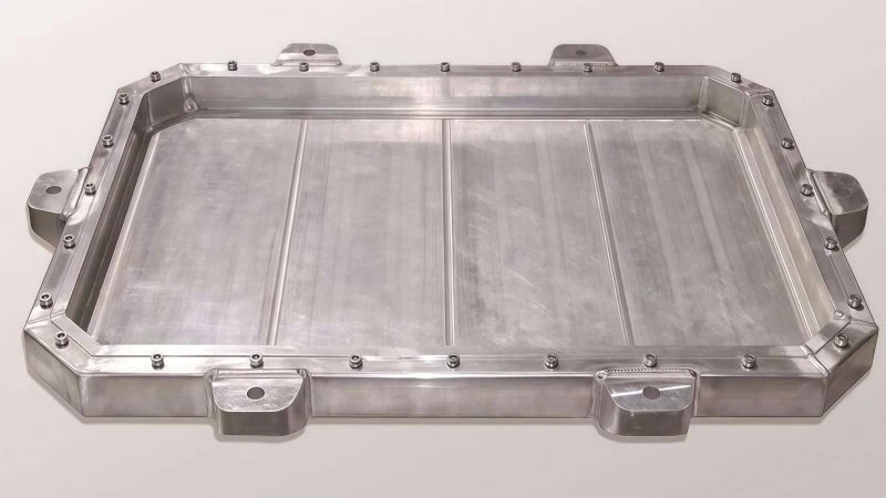
How can manufacturers efficiently mill complex extruded aluminum profiles for electric vehicle battery trays without sacrificing dimensional accuracy or exploding tooling budgets?
Manufacturers achieve high-efficiency milling of extruded aluminum battery trays by implementing advanced Polycrystalline Diamond (PCD) tooling1 strategies. By optimizing tool micro-geometries, utilizing high-speed climb milling toolpaths, and applying rigid toolholding systems, facilities successfully eliminate thin-wall vibration, prevent material adhesion, and drastically lower the overall cost-per-part during high-volume production.
Overcoming Machining Challenges in Complex Aluminum Profiles
Milling extruded aluminum for electric vehicle battery trays presents specific structural and thermal obstacles, primarily severe vibration in thin-walled sections, rapid built-up edge (BUE) formation, and excessive heat generation. To stabilize these delicate structures, prevent material adhesion, and dissipate heat rapidly, manufacturers utilize Polycrystalline Diamond (PCD) tooling. This approach ensures tight dimensional tolerances and flawless surface finishes during high-speed CNC operations.
Managing Vibration in Thin-Walled Structures
Electric vehicle (EV) battery trays rely heavily on 6000-series aluminum extrusions2. These designs save significant weight. However, they feature extremely thin walls and wide spans. Why does this structural design matter? Thin walls act exactly like an unsupported overhanging rib during milling operations. The cutter strikes the metal, and the thin structure reverberates. Therefore, harmonic vibration, commonly known as chatter, becomes a severe problem.
Chatter instantly destroys surface finishes. Furthermore, it damages the cutting tool. To maintain structural integrity, manufacturers must minimize cutting forces. PCD tools naturally generate significantly lower cutting forces than standard solid carbide3. Their extreme sharpness slices through the aluminum cleanly without pushing the material.
Structural Behavior Comparison
| Machining Condition | Solid Aluminum Billet | Extruded Thin-Wall Profile |
|---|---|---|
| Overall Rigidity | Very High | Extremely Low |
| Vibration Risk | Minimal | High (Chatter occurs easily) |
| Tolerance Control | Straightforward | Difficult (High deflection risk) |
| Required Cutting Force | Standard | Must be strictly minimized |
By reducing the overall cutting pressure, PCD tools prevent the extrusion from deflecting away from the spindle. As a result, the final battery tray stays within its strict dimensional tolerances.
Eliminating Built-Up Edge and Material Adhesion
Aluminum is notoriously soft and gummy. Consequently, it tends to stick directly to the cutting tool during milling. This specific phenomenon is known as Built-Up Edge (BUE)4. Is BUE really that destructive to the process? Yes. When aluminum welds itself to the cutting edge, the tool effectively becomes blunt.
A blunt tool tears the material instead of cutting it cleanly. Therefore, BUE directly leads to rejected parts and broken end mills. Standard carbide tools struggle constantly with this adhesion. In contrast, PCD possesses a uniquely low coefficient of friction.
- Friction Coefficient of Carbide: Approximately 0.4 to 0.6.
- Friction Coefficient of PCD: Approximately 0.1.
Because the PCD surface is exceptionally slick, aluminum chips slide off the tool face effortlessly. The chips evacuate the cutting zone completely before they can weld to the edge.
- BUE destroys critical sealing surfaces on the battery tray.
- Material adhesion increases sudden tool failure rates.
- Sticky aluminum chips block essential coolant pathways.
PCD tooling naturally resists this material adhesion. Thus, it guarantees a clean shear plane and a mirror-like surface finish on the final part.
Controlling Heat Generation During High-Speed Passes
High-speed milling generates intense friction. Friction creates massive amounts of heat. Unfortunately, aluminum expands significantly when exposed to heat. If the battery tray absorbs too much heat during machining, it will physically warp. Upon cooling, the warped tray will fall entirely out of tolerance.
Therefore, effective thermal management remains absolutely critical. The primary goal is to force the heat into the aluminum chip, not into the actual battery tray. Think of this process like surface milling a thin, unsupported aluminum plate. If the feed rate is too slow, the tool dwells, and the entire plate absorbs the heat and warps from thermal soak. You must move quickly with an optimized chip load to keep the heat localized in the chip. PCD features an incredibly high thermal conductivity. It pulls heat away from the cutting zone rapidly.
Thermal Properties Impacting Tooling
| Tool Material | Thermal Conductivity | Heat Dissipation Efficiency |
|---|---|---|
| Solid Carbide | ~100 W/m·K | Moderate |
| PCD | ~500 W/m·K | Excellent |
This rapid heat transfer ensures the battery tray remains structurally stable. Maintaining a cool workpiece prevents dimensional distortion. Consequently, the battery tray maintains its exact shape for the final assembly process.

Optimizing PCD Tool Geometries for 6000-Series Alloys
To cleanly machine 6000-series aluminum, manufacturers must optimize the specific micro-geometry of the PCD tool. This precision requires selecting a medium diamond grain size, utilizing high positive rake angles, and applying an exact edge radius. These geometric configurations prevent premature edge chipping, ensure rapid chip evacuation, and deliver superior surface finishes on delicate extruded profiles.
Selecting the Optimal Diamond Grain Size
PCD material consists of synthetic diamond particles bonded together under extreme pressure. Therefore, the physical size of these diamond grains directly determines the tool’s performance. Should you choose fine, medium, or coarse grains for aluminum extrusions? The answer lies in finding the perfect balance between edge sharpness and wear resistance.
For 6000-series aluminum, such as 6061 or 6063, a medium grain size generally performs best.
- Fine Grains (Approx. 2-4 µm): These create a razor-sharp cutting edge. They produce brilliant surface finishes. However, they wear out much faster during continuous production.
- Medium Grains (Approx. 10 µm): This is the industry standard for battery trays. It offers an excellent combination of extended tool life and clean cutting action.
- Coarse Grains (Approx. 25 µm or larger): These provide maximum abrasion resistance. Unfortunately, they leave microscopic jagged edges on the tool. This causes rougher finishes on the final part.
Consider how a grinding wheel operates in a machine shop. A coarse grit wheel removes heavy material rapidly but leaves deep scratches. Conversely, a fine grit wheel polishes the metal but clogs easily. PCD grain sizes follow this exact same principle. Because exact micron classifications for these grain grades can vary significantly between different manufacturers, always verify the specific dimensional range with your tooling supplier before purchasing.
Applying Positive Rake Angles for Efficient Chip Evacuation
The rake angle5 determines how the cutting edge strikes the aluminum surface. Extruded aluminum is highly malleable. Therefore, it requires a very specific approach angle to cut cleanly.
If you use a neutral or negative rake angle, the tool will push or “plow” the metal. This pushing action creates massive pressure. Consequently, it causes thin battery tray walls to bend out of tolerance. Instead, manufacturers must utilize high positive rake angles.
A positive rake angle (often between +15° and +25°) creates a sharp, scooping motion. It shears the aluminum effortlessly. This sharp shear plane forces the metal chip to curl up and snap off quickly. As a result, the chips evacuate the cutting zone immediately.
Rake Angle Comparison for 6000-Series Aluminum
| Angle Type | Cutting Action | Part Deflection Risk | Best Application |
|---|---|---|---|
| Negative Rake | Plowing / Smearing | Very High | Hardened Steels, Cast Iron |
| Neutral Rake | Scraping | Moderate | Brass, Hard Plastics |
| Positive Rake | Sharp Shearing | Minimal | Soft, Gummy Aluminum |
Think of lathe turning a soft brass rod compared to a hardened steel shaft. Soft materials require a sharp attack angle to peel the chip away smoothly without generating excessive tool pressure. Extruded aluminum behaves similarly on a milling machine. High positive rakes reduce the cutting forces dramatically. Ultimately, this protects the fragile extrusion from structural deformation.
Maintaining Up-Sharp Edges and Nose Radius Adjustments
When milling 6000-series aluminum, the PCD tool must feature a “dead-sharp” or “up-sharp” cutting edge. While edge preparation (such as microscopic honing) is common practice when machining cast iron or hardened steel to prevent edge chipping, applying it to aluminum cutting tools is a critical mistake.
“Intentionally dulling a PCD tool with edge preparation turns a clean shearing action into a destructive plowing action, drastically increasing radial tool pressure.”
Because extruded aluminum is soft and gummy, a sharp edge is absolutely necessary to slice through the material cleanly. If the edge is honed or rounded, the tool will push the metal instead of cutting it. This pushing force causes the thin-walled battery tray to deflect rapidly, leading directly to scrapped parts. Furthermore, this friction instantly promotes built-up edge (BUE). While an up-sharp diamond edge is theoretically more fragile, the extreme softness of the aluminum prevents premature chipping.
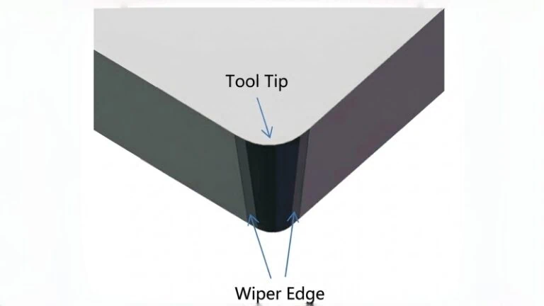
Additionally, the nose radius (the rounded corner of the cutting insert) requires careful adjustment. The size of this radius directly impacts two critical factors: surface finish and radial cutting pressure.
- Larger Nose Radius: A larger radius strengthens the tool tip. It also spreads the feed marks over a wider area. Consequently, it creates a much smoother surface finish.
- Smaller Nose Radius: A smaller radius generates far less radial tool pressure.
For thin-walled battery trays, tool pressure is the enemy. If the nose radius is too large, it pushes the thin wall away during the cut. Therefore, engineers must select a moderate nose radius (typically around 0.4mm to 0.8mm). This specific size provides enough strength to maintain surface finish. At the same time, it keeps cutting pressure low enough to prevent the aluminum profile from bending. Adjusting these micro-geometries precisely guarantees a stable, repeatable machining process.
Formulating High-Efficiency Toolpaths and Cutting Parameters
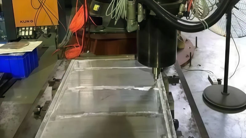
By calculating precise spindle speeds, selecting specific milling directions, and designing specialized finishing passes, CNC programmers maximize material removal rates while strictly maintaining dimensional accuracy. Optimizing these toolpaths directly prevents the formation of costly edge burrs and minimizes structural deflection during high-volume production.
Determining Ideal Spindle Speeds and Feed Rates
Polycrystalline Diamond (PCD) tools possess exceptional hardness. Therefore, they operate at incredibly high speeds. These speeds would instantly destroy standard carbide end mills. Consequently, CNC programmers must establish entirely new baselines for spindle speed (RPM) and feed rate6.
What happens if you spin a tool incredibly fast but feed it into the material too slowly? The tool simply rubs against the aluminum instead of cutting it. This rubbing action creates massive friction. Ultimately, this friction leads to severe dimensional errors on the battery tray. To prevent this, you must maintain a proper “chip load.” The chip load is the exact thickness of the aluminum removed by each cutting edge during one revolution.
When milling 6000-series aluminum extrusions, PCD tools typically run at surface speeds between 1,000 and 3,000 meters per minute.
Starting Parameter Comparison
| Tool Material | Typical Cutting Speed (Vc) | Feed Per Tooth (fz) |
|---|---|---|
| Solid Carbide | 300 – 800 m/min | 0.05 – 0.15 mm |
| PCD | 1,000 – 3,000 m/min | 0.10 – 0.25 mm |
Note: Optimal baseline parameters rely heavily on your machine’s spindle dynamics, fixture rigidity, and the specific aluminum alloy tempering; always consult the tool manufacturer for exact starting values.
Think of this process like feeding a thick aluminum billet into a high-speed indexable face mill. If the feed rate is too low, the inserts rub the surface rather than cutting it, generating excessive heat instead of chips. Similarly, PCD tools require aggressive feed rates to perform efficiently and evacuate heat properly.
Climb Milling Versus Conventional Milling Approaches
The direction the cutting tool moves across the aluminum is critical. In CNC machining, you generally choose between two distinct toolpaths: climb milling and conventional milling.
In conventional milling, the cutter rotates against the direction of the feed. This creates a lifting action. The tool constantly tries to pull the workpiece up from the table. For a heavy steel engine block, this might not matter. However, for a thin-walled battery tray, this lifting force is disastrous. It bends the fragile extrusion away from the fixture.
Conversely, climb milling is universally preferred for extruded aluminum. In this approach, the cutter rotates into the direction of the feed.
“Climb milling naturally pushes the workpiece downward into the machining fixture, ensuring maximum stability for thin-walled components.”
Why is this downward force so beneficial?
- It stabilizes the part: The cutting action actively holds the flimsy battery tray securely against its clamps.
- It improves chip evacuation: The chip starts thick and ends thin. This allows the chip to eject behind the cutter safely.
- It reduces tool wear: The cutting edge immediately bites into the material, rather than rubbing against the surface first.
Always program your finishing toolpaths using the climb milling technique. This strategy guarantees the flattest possible sealing surfaces on the final battery tray.
Advanced Strategies for Burr-Free Edge Finishing
A burr is a sharp, jagged piece of metal left on the edge of a machined part. In EV manufacturing, burrs are strictly forbidden. A single burr can puncture a battery cell or prevent a watertight seal. Hand-deburring battery trays is slow, expensive, and inconsistent. Therefore, you must eliminate burrs directly inside the CNC machine using smart toolpaths.
Aluminum is a very ductile material. It loves to bend. When a cutter exits an edge straight on, it often pushes the metal over the edge rather than shearing it off cleanly. This pushing action creates the burr.
To solve this, programmers use a strategy called “roll-in and roll-out” arc engagement.
- Never plunge vertically: Do not drop the cutter directly onto the edge of the profile.
- Arc into the cut: Program the tool to approach the edge in a smooth, sweeping arc.
- Arc out of the cut: As the tool finishes the pass, it should sweep away from the material in a continuous curve.
Think of this like face milling the edge of a brittle cast iron block. If the cutter drives straight off the end of the material, it causes heavy edge breakout. You must ease the cutter out of the cut smoothly.
Furthermore, maintaining continuous tool engagement prevents burrs. Do not let the tool lift off the surface and re-enter multiple times. Every entry and exit point is a potential location for a burr to form. By combining continuous toolpaths with arc engagements, manufacturers produce perfectly clean, burr-free battery trays straight off the machine.
Maximizing ROI and Tool Life in High-Volume Production
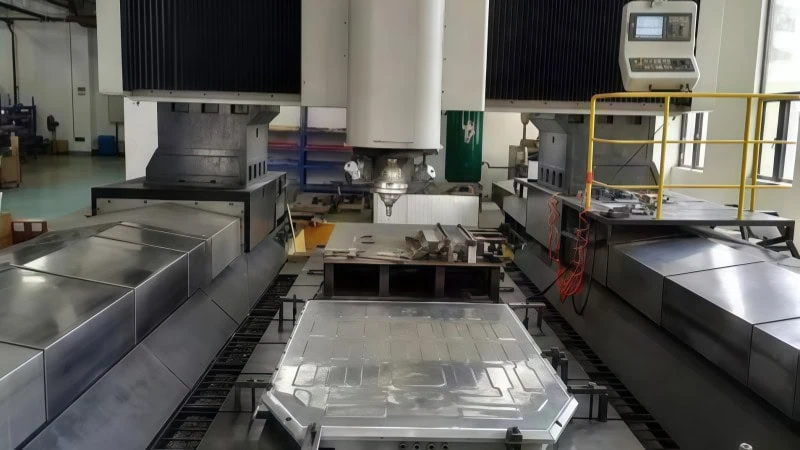
Despite higher initial costs, PCD tooling drastically reduces the overall cost-per-part across high production volumes by leveraging extreme wear resistance. Facilities maximize this tool life by deploying ultra-rigid toolholding systems and utilizing precise coolant application techniques, effectively eliminating destructive runout and ensuring continuous thermal stability.
Cost-Per-Part Analysis: PCD Versus Solid Carbide
PCD cutting tools cost significantly more than solid carbide options. Initially, this high price tag alarms many purchasing managers. However, looking only at the upfront cost is a major financial mistake. In high-volume manufacturing, the only metric that truly matters is the final cost-per-part7.
Why does cost-per-part matter so much? Every minute a CNC machine sits idle for a tool change, the facility loses money. Solid carbide tools wear out quickly when cutting abrasive aluminum extrusions. Consequently, operators must stop the machine frequently to replace them. In contrast, PCD tools stay in the spindle for months.
Think of a small job shop upgrading from a manual knee mill to a fully automated CNC machining center. The initial investment is massive. However, the automated machine produces parts ten times faster. Therefore, the long-term cost of producing each part drops dramatically. PCD tooling follows this exact same economic principle.
Tooling Cost and Efficiency Comparison
| Metric | Solid Carbide End Mill | PCD End Mill |
|---|---|---|
| Initial Purchase Price | Low (Approx. $100) | High (Approx. $800) |
| Average Parts Produced | 500 parts | 25,000+ parts |
| Machine Downtime | High (Frequent changes) | Extremely Low |
| Estimated Cost-Per-Part | $0.20 | $0.03 |
By drastically reducing machine downtime, PCD tools pay for themselves quickly. Furthermore, they provide predictable, long-term stability for automated battery tray production lines.
Implementing Rigid Toolholding Systems to Prevent Runout
Tool life depends entirely on operational stability. Specifically, CNC programmers must eliminate a destructive force known as runout8. What is runout? It occurs when the cutting tool does not rotate perfectly on its center axis. Instead, it wobbles slightly as it spins.
Standard carbide tools can absorb a small amount of this wobble. Diamond, however, is incredibly hard but also very brittle. Consequently, even a microscopic wobble causes uneven cutting forces. These uneven forces strike the diamond edge repeatedly. Ultimately, this causes the PCD insert to shatter prematurely.
“Minimizing Total Indicator Runout (TIR) to less than 3 microns is absolutely essential for maximizing the lifespan of any diamond cutting tool.”
To prevent runout, standard collet chucks are completely inadequate. Instead, manufacturers must utilize highly rigid toolholding systems.
- Shrink-Fit Holders: These holders use thermal expansion to grip the tool securely. They offer near-perfect concentricity.
- Hydraulic Chucks: These systems use pressurized fluid to clamp the tool evenly. They provide excellent holding power and naturally dampen vibrations.
Consider a lathe chuck holding a heavy steel shaft slightly off-center. As the shaft spins, the wobble creates violent, uneven forces against the turning insert. The insert breaks quickly. An end mill wobbling in a standard collet experiences the exact same destructive forces. By investing in shrink-fit or hydraulic toolholders, facilities protect their expensive PCD tools from catastrophic failure.
Coolant Application Techniques for Extended Tool Longevity
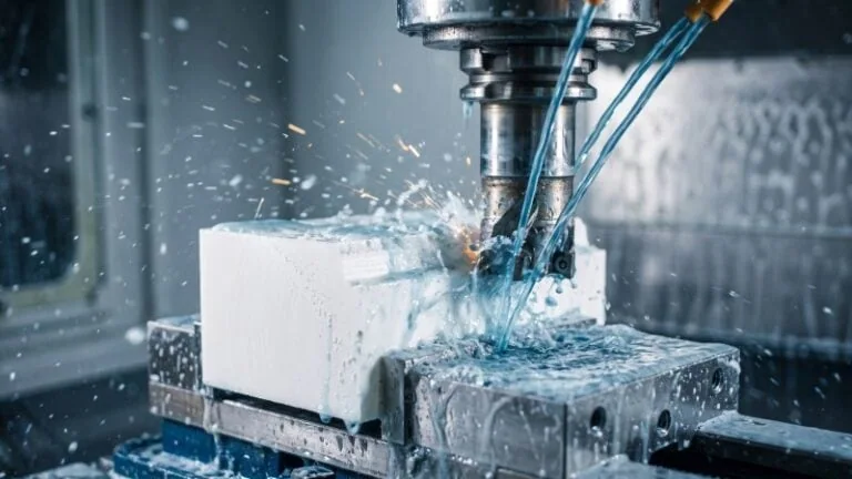
While PCD handles heat exceptionally well, coolant remains vital in high-volume extrusion milling. Coolant serves two primary functions. First, it lubricates the cutting edge. Second, it flushes aluminum chips out of the cutting zone.
If chips remain in the cutting zone, the tool will cut them again. This process is called recutting. Recutting instantly destroys tool life. Therefore, the coolant system must clear chips instantly.
Like using a high-pressure air blast to clear deep metal shavings during a deep-hole drilling operation, precise coolant delivery physically pushes chips away safely. For battery tray manufacturing, standard flood coolant is often insufficient.
Instead, facilities use Through-Spindle Coolant (TSC). TSC forces high-pressure fluid directly through the center of the tool. Consequently, the fluid blasts out directly at the cutting edge. This technique guarantees the chips evacuate immediately. Additionally, many EV manufacturers now use Minimum Quantity Lubrication (MQL)9. MQL uses a fine mist of specialized oil instead of traditional water-based fluids. This method reduces fluid waste while still preventing chips from welding to the cutter. Proper coolant application directly extends the life of the PCD tool, ensuring thousands of precise battery trays are produced without interruption.
Conclusion
Successfully machining extruded aluminum for EV battery trays requires moving beyond traditional methods. Thin-walled structures, gummy aluminum alloys, and the demand for zero-defect edges mandate a highly specialized approach. By integrating PCD tooling with optimized micro-geometries, climb milling toolpaths, and rigid toolholding, manufacturers can transform complex milling challenges into a streamlined, highly profitable process. Investing in these advanced strategies not only ensures superior part quality but also delivers the lowest possible cost-per-part in high-volume production.
References
- Polycrystalline Diamond (PCD) Tooling1 – A comprehensive guide on the definition, properties, and applications of PCD tools by ZYDiamondTools.
- 6000-Series Aluminum Extrusions2 – AZoM article detailing the properties, composition, and applications of 6000 series aluminum alloys.
- Standard Solid Carbide3 – ZYDiamondTools blog post detailing the core differences in performance and application between PCD and carbide cutting tools.
- Built-Up Edge (BUE)4 – Wikipedia article explaining the formation, causes, and effects of built-up edge during machining operations.
- Rake Angle5 – ScienceDirect topic page detailing the mechanics and importance of rake angles in cutting tool geometry.
- Spindle Speed (RPM) and Feed Rate6 – ZYDiamondTools online speeds and feeds calculator designed to optimize machining parameters.
- Cost-Per-Part7 – ZYDiamondTools guide explaining Total Cost of Ownership (TCO) and how to evaluate real tooling costs.
- Runout8 – Wikipedia article detailing run-out in mechanical engineering and its impact on rotating tools and components.
- Minimum Quantity Lubrication (MQL)9 – ScienceDirect topic page explaining the principles and applications of MQL in advanced machining.