-
Whatsapp: +86 13526572721
-
Email: info@zydiamondtools.com
-
Address: AUX Industrial Park, Zhengzhou City, Henan Province, China
-
Whatsapp: +86 13526572721
-
Email: info@zydiamondtools.com
-
Address: AUX Industrial Park, Zhengzhou City, Henan Province, China

What is “Wiper Geometry” on PCBN Inserts and How Does It Improve Surface Finish?
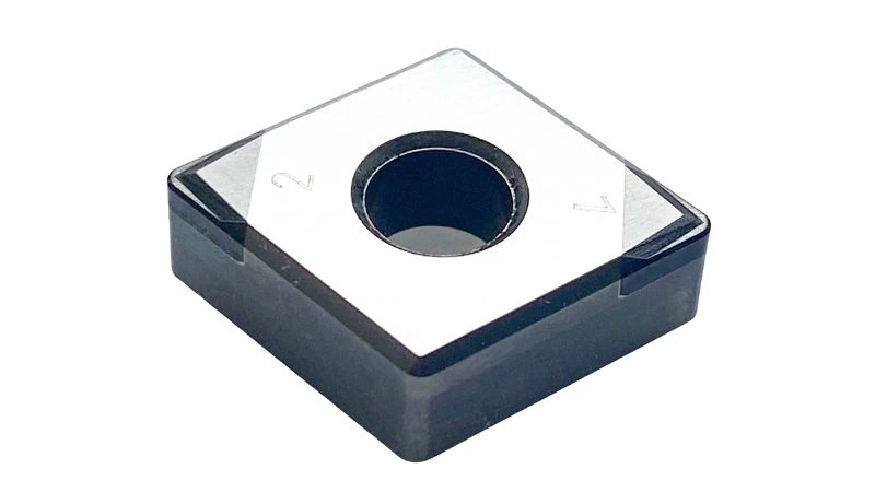
So, what exactly is wiper geometry on a PCBN insert1, and how does it fundamentally change the surface finish of hardened steel2 components?
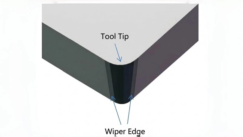
Wiper geometry is a specialized cutting tool design that replaces the standard single nose radius with a series of blended micro-radii, creating an extended flat trailing edge. As the insert feeds across the workpiece, this flat section physically irons out the microscopic peaks of the feed marks, significantly reducing surface roughness3 (Ra and Rz) and allowing machinists to achieve grinding-level quality or double their feed rates.
The Mechanics Behind the Micro-Geometry
Understanding the physical difference between a wiper insert and a standard cutting tool is essential for maximizing surface finish capabilities.
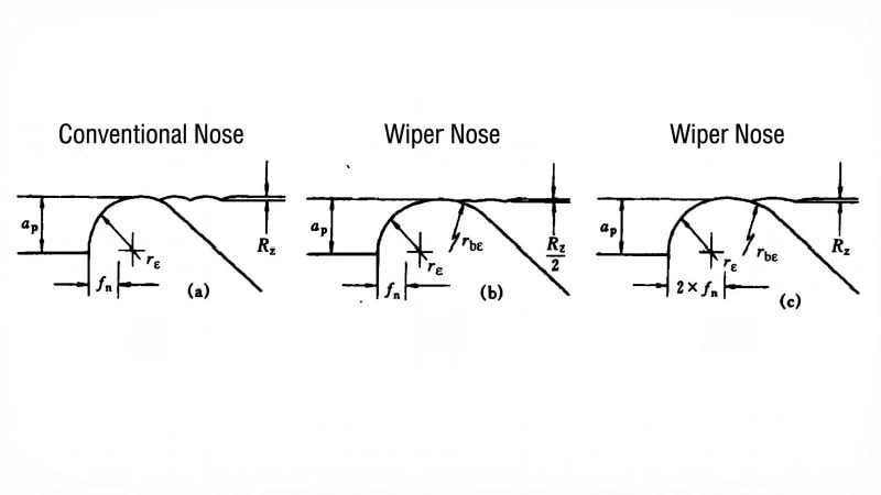
Wiper geometry on a PCBN insert replaces the standard single-radius tool nose with a complex sequence of blended micro-radii. This multi-radii design creates an extended, nearly flat contact area along the trailing edge. Instead of leaving a grooved profile on the workpiece, this flattened section physically “wipes” or irons out the peaks of the feed marks as the tool advances, drastically reducing the final surface roughness.
Conventional Nose Radius vs Wiper Design
Think about standard turning operations. A conventional insert features a simple, round tip. We call this the nose radius. When this round tip moves across a spinning metal workpiece, it shears away material. However, it also leaves behind a continuous, microscopic groove. This is similar to how a single-point threading tool cuts distinct ridges, just on a much smaller scale.
A wiper insert fundamentally changes this cutting edge. It does not use one simple curve. Instead, tool engineers combine several different micro-radii. This combination creates a small, flat-looking segment right behind the main cutting point. Therefore, the contact area against the workpiece becomes much wider.
| Feature | Conventional Nose Radius | Wiper Design |
|---|---|---|
| Nose Shape | Single, constant curve | Multiple blended curves (micro-radii) |
| Contact Area | Small, point-like contact | Extended, flattened contact line |
| Edge Profile | Leaves distinct peaks and valleys | Smoothes out peaks during the cut |
How the Wiping Action Flattens Feed Marks
How exactly do those blended curves eliminate rough surfaces? The answer lies in the trailing edge of the tool.
When you use a standard insert, the round tip creates a spiral pattern. The faster your feed rate, the wider the spacing between the peaks of this spiral. The wiper geometry changes this interaction completely. As the front part of the PCBN insert cuts the hardened steel, the extended wiper section trails right behind it.
“The wiper edge acts exactly like a burnishing roller on a lathe, physically ironing out the microscopic peaks of the feed marks before the tool moves away.”
Because this trailing edge is flat, it pushes down the high spots left by the initial cut. It literally wipes the surface smooth. For example, a standard nose radius might leave a surface roughness (Ra) of 0.8 µm at a given feed. By switching to a wiper design, the ironing action can drop that Ra down to 0.2 µm under the exact same feed rate.
Key Productivity Advantages in Hard Turning
Why should a machine shop invest in wiper PCBN inserts for their hard turning operations?
Wiper PCBN inserts deliver immense productivity gains by combining roughing and finishing into a single lathe process. They eliminate the need for secondary cylindrical grinding, allow for a 100% increase in feed rates while maintaining surface finish, and frequently extend tool life by distributing extreme cutting heat across a wider edge.
Achieving Grinding-Level Quality
Historically, achieving a mirror-like finish on hardened steel required a dedicated grinding machine. Hard turning with conventional inserts simply could not match a grinding wheel’s surface finish. However, wiper geometry changes this rule completely.
Using a PCBN insert with a wiper edge allows you to achieve surface finishes previously thought impossible on a standard lathe. You can consistently reach a surface roughness (Ra) of 0.2 to 0.4 µm. This quality is completely comparable to standard cylindrical grinding4.
Think of it like using a broad face mill instead of a narrow end mill to flatten a large metal plate. The broader tool naturally creates a much smoother, flatter surface. By achieving grinding-level quality directly on the lathe, shops can entirely eliminate the separate grinding process. Therefore, this saves massive amounts of time, labor, and equipment costs.
Since exact surface finish capabilities depend heavily on your specific machine’s rigidity, the workpiece material, and the specific PCBN grade, it is best to verify the expected Ra range and parameters with your tooling supplier.
Doubling Feed Rates Without Sacrificing Quality
The most famous benefit of wiper geometry is the massive boost to machining speed. In standard turning operations, surface finish and feed rate5 are strictly tied together. If you push the tool faster, the surface instantly gets rougher.
Wiper inserts break this traditional rule. Because the trailing edge physically irons out the feed marks, you can increase your feed rate dramatically. In fact, you can typically double the feed rate while maintaining the exact same surface finish as a conventional insert.
| Tool Type | Feed Rate (mm/rev) | Resulting Surface Finish (Ra) |
|---|---|---|
| Conventional PCBN | 0.10 | 0.4 µm |
| Wiper PCBN (Focus on Quality) | 0.10 | 0.2 µm (Improved Finish) |
| Wiper PCBN (Focus on Speed) | 0.20 | 0.4 µm (Same Finish, Double Speed) |
“A wiper insert allows a CNC lathe to cut cycle times in half during finishing passes, directly doubling the machine’s daily output for that operation.”
This means you do not have to choose between speed and quality anymore. You can keep your current quality standards and finish parts twice as fast. Alternatively, you can keep your current cycle time and deliver a dramatically better, smoother surface.
Impact on Tool Life and Wear Resistance
You might assume that a wider cutting edge would wear out faster due to increased friction. Surprisingly, the exact opposite is true. Wiper geometry often improves the overall tool life of PCBN inserts.
When turning hardened materials (typically 58-62 HRC6), extreme heat is generated right at the cutting zone. A conventional nose radius concentrates all this intense heat and friction into a tiny, single point. Consequently, this causes rapid crater wear and notch wear at that specific spot.
The extended wiper edge spreads the cutting forces and the thermal load over a much larger area. This is very similar to how a multi-tooth broach distributes cutting loads far better than a single-point shaping tool. By sharing the physical burden across a wider edge, the PCBN material degrades much slower. Ultimately, you get more finished parts per cutting edge, significantly reducing your overall tooling costs.
Essential Application Rules and Machine Setup
Proper machine setup is non-negotiable; a wiper PCBN insert will only perform correctly if the lathe is configured to support its unique geometry.
To successfully apply wiper PCBN inserts, machinists must use toolholders that provide the exact lead angle designed for the specific wiper geometry, typically between 90 and 95 degrees. Furthermore, the machine tool, workholding, and spindle must possess maximum structural rigidity to handle increased radial cutting forces. Finally, operators must precisely balance the depth of cut and feed rate to keep the wiper flat fully engaged with the workpiece.
Selecting the Correct Lead Angle
The lead angle, also known as the entering angle, dictates exactly how the cutting edge approaches the part. This is absolutely the most critical setup factor for a wiper insert. The extended flat wiper section must sit perfectly parallel to the machined surface. If the angle tilts even slightly, the tool will fail to perform. It will either dig heavily into the metal, or the wiper will completely miss the surface, leaving standard rough feed marks.
For instance, most standard diamond-shaped wiper inserts require a precise 93-degree lead angle toolholder for straight outer-diameter turning. This setup is very similar to aligning a heavy parting-off blade perfectly square to a lathe spindle. If the parting blade is crooked, it binds, rubs, and breaks. The wiper edge acts the exact same way.
Because specific micro-radii designs and edge preparations differ between brands, you must always consult your insert supplier to confirm the exact lead angle required for their specific wiper series.
Rigidity Requirements to Prevent Chatter
Wiper geometries naturally create a much larger physical contact area against the hardened steel. Consequently, this broad contact generates significantly higher radial cutting forces. These forces actively push the tool directly away from the workpiece during the cut.
If your machine or workholding lacks rigidity, this outward pressure will immediately cause chatter7. Chatter is a severe, high-frequency vibration. It completely destroys the smooth surface finish. Moreover, chatter will instantly chip the brittle PCBN cutting edge. Therefore, everything in the setup must remain perfectly stiff. You must use massive, rigid tool blocks, high-quality collets, and keep the tool overhang as short as mechanically possible.
Think about using a long, unsupported boring bar8 inside a deep cylinder. If you take a heavy cut, the radial pressure causes the long bar to flex and squeal loudly. A wiper insert creates that exact same push-back pressure on the outside of the part, requiring a rock-solid foundation to absorb it.
Depth of Cut and Feed Rate Parameters
You cannot run a wiper insert using the exact same parameters as a standard round-nose insert. You must deliberately adjust your cutting speed, feed, and depth to match the broader geometry.
The feed rate must be high enough to make the wiping action actually work. If you feed the tool too slowly, the broad edge simply rubs against the metal instead of cutting it. This rubbing generates massive friction heat and destroys the tool life quickly.
| Cutting Parameter | Conventional PCBN | Wiper PCBN |
|---|---|---|
| Typical Feed Rate | 0.05 to 0.10 mm/rev | 0.15 to 0.30 mm/rev |
| Typical Depth of Cut | 0.10 to 0.25 mm | 0.15 to 0.30 mm |
“Running a wiper insert too slowly is the most common mistake machinists make, leading to immediate rubbing and premature tool failure.”
Therefore, operators must confidently push the feed rate higher. This forces the trailing wiper edge to aggressively iron the surface, delivering the high productivity the tool is designed for.

When to Avoid Using Wiper Inserts
Are there specific machining situations where choosing a wiper PCBN insert is actually the wrong decision?
Yes, machinists must avoid wiper PCBN inserts when turning thin-walled parts, long slender shafts, or complex internal profiles. The extended cutting edge creates high radial pressure that bends unsupported metal, while the wide flat geometry cannot physically fit into tight undercuts or machine sharp internal corners without gouging the workpiece.
Thin-Walled or Long Slender Components
As we know, the wide trailing edge of a wiper insert presses firmly against the metal. This broad contact creates very high radial cutting forces. Consequently, these forces push the workpiece directly away from the cutting tool.
If you machine a short, solid steel block, this push-back is not an issue. However, if you turn a long, unsupported shaft, this pressure becomes a massive problem.
Imagine applying heavy radial pressure to the middle of an unsupported steel rod on a lathe. Instead of cutting cleanly, the tool simply pushes the rod away, causing the metal to flex. Turning a long shaft with a wiper insert causes this exact same deflection.
This deflection ruins your dimensional accuracy. The final part will taper, vibrate loudly, and ultimately fail quality inspections. A common industry rule states you should avoid standard wiper inserts if your part’s Length-to-Diameter (L/D) ratio exceeds 4:1. Beyond this ratio, the shaft flexes too much under the heavy load.
Therefore, for thin-walled aerospace rings or long drive shafts, a conventional small-radius insert is much safer. The smaller point of contact reduces radial pressure and keeps the fragile part stable.
Internal Profiling and Undercutting Limitations
Besides flexibility issues, wiper inserts also face strict geometric limits. You simply cannot use them for complex internal profiling or deep undercuts.
The wiper edge features an extended flat section. Because of this extra width, the tool needs plenty of physical clearance to operate safely.
Consider using a wide parting-off blade on a lathe. You cannot use that heavy blade to plunge a tiny, intricate O-ring groove. The tool is simply too bulky for the tight space. In the exact same way, a wiper insert cannot navigate tight internal corners.
If your engineering blueprint requires a sharp 90-degree internal shoulder, a wiper tool will fail. As the tool approaches the wall, the trailing wiper edge will crash into the shoulder long before the main cutting point finishes the corner.
“Using a wiper insert in a confined space almost always results in severe gouging, damaging the workpiece and shattering the PCBN tip.”
This crash causes instant scrap. Therefore, standard round-nose inserts remain the absolute best choice for small internal bores and complex part profiles.
| Part Feature | Conventional PCBN | Wiper PCBN |
|---|---|---|
| Outer Diameter (Rigid) | Acceptable | Highly Recommended |
| Long Slender Shafts | Recommended (Low Force) | Not Recommended (High Deflection) |
| Tight Internal Shoulders | Recommended (Fits Easily) | Not Recommended (Causes Gouging) |
| Thin-Walled Bushings | Recommended | Not Recommended |
Conclusion
Wiper geometry on PCBN inserts represents a massive leap forward in hard turning technology. By effectively ironing out feed marks through a multi-radii edge design, these tools bridge the gap between traditional turning and cylindrical grinding. When set up correctly with proper lead angles and rigid machinery, they allow shops to achieve superior surface finishes while doubling productivity and extending tool life. However, they are not a universal solution; understanding their limitations on long, slender, or internally complex components is vital to avoiding chatter and part rejection.
By applying these principles, you can optimize your machining processes, reduce cycle times, and lower your overall tooling costs. If you need further assistance selecting the exact wiper geometries or establishing the optimal parameters for your specific turning applications, please feel free to contact us.
References
- PCBN insert1 – ZYDiamondTools product page detailing standard and custom CBN/PCBN inserts designed for hard material machining.
- hardened steel2 – ZYDiamondTools blog post explaining the critical role of CBN inserts in machining hardened steel components.
- surface roughness3 – Wikipedia article defining surface roughness and outlining key measurement parameters like Ra and Rz.
- cylindrical grinding4 – Wikipedia reference page detailing the mechanics and applications of standard cylindrical grinding operations.
- feed rate5 – Wikipedia guide on speeds and feeds, defining how feed rates impact machining and surface quality.
- 58-62 HRC6 – Wikipedia article on the Rockwell scale, detailing the HRC hardness measurement system used for metals.
- chatter7 – Wikipedia overview of machining vibrations, explaining what chatter is and how it damages workpieces.
- boring bar8 – Wikipedia technical page explaining the boring process and the tools used to enlarge internal diameters.