-
Whatsapp: +86 13526572721
-
Email: info@zydiamondtools.com
-
Address: AUX Industrial Park, Zhengzhou City, Henan Province, China
-
Whatsapp: +86 13526572721
-
Email: info@zydiamondtools.com
-
Address: AUX Industrial Park, Zhengzhou City, Henan Province, China

Machining EV Motor Housings: Maximizing Efficiency with Custom PCD Tools
How can manufacturers maximize efficiency and overcome severe production bottlenecks when machining complex aluminum EV motor housings?
Manufacturers maximize efficiency by replacing standard sequential carbide tools with custom combination Polycrystalline Diamond (PCD)1 tooling. Custom PCD tools consolidate multiple operations—such as boring, facing, and chamfering—into a single pass. This strategic approach mitigates abrasive wear from high-silicon aluminum, minimizes thin-wall deformation through optimized cutting geometries, and drastically reduces overall cycle times to achieve a lower cost per part.
The Limitations of Standard Tooling in High-Volume Aluminum Production
Why do standard cutting tools frequently fail when machining electric vehicle motor housings at high volumes?
Standard solid carbide tools2 wear out rapidly when cutting the abrasive aluminum alloys used in EV housings. Furthermore, they require multiple separate operations for complex features. This sequential process drastically increases cycle times. High-volume EV production ultimately demands more durable solutions to maintain efficiency.
Abrasive Wear in High-Silicon Alloys
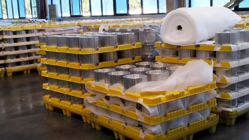
EV motor housings rely on specific cast aluminum alloys3. These materials usually contain a high silicon content, often between 9% and 12%. Manufacturers use silicon because it improves the flow of liquid metal during the High-Pressure Die Casting (HPDC)4 process.
However, silicon is an extremely hard element. It creates a highly abrasive environment for standard cutting tools. Machining high-silicon aluminum5 with standard carbide is similar to cutting hardened steel with a standard high-speed steel (HSS) drill bit. The cutting edge dulls rapidly due to intense friction.
The Impact on Part Quality
As the tool edge degrades, cutting forces steadily increase. This inevitably leads to poor surface finishes on the motor housing. Eventually, the dimensions fall out of the acceptable tolerance range.
Standard solid carbide tools might process only 1,500 to 2,000 parts before failing. Replacing worn tools frequently interrupts active production lines and significantly drives up the overall tooling cost per part.
Cycle Time Penalties of Sequential Tool Changes
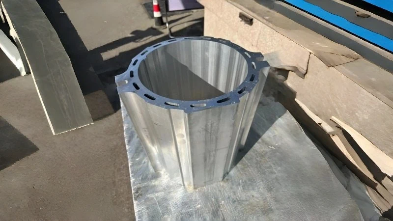
Standard cutting tools handle one specific job at a time. Therefore, machining a complex EV motor housing requires a sequential approach. Because the massive central stator bore is already pre-cast into the housing blank to save weight, standard solid drills cannot be used. First, a standard rough boring tool6 or interpolation mill removes the heavy casting skin from the pre-cast hole. Next, a semi-finishing boring bar sizes the bore. Finally, a chamfer mill finishes the sharp edges.
This traditional method requires the CNC machine to perform multiple tool changes. Every single tool change stops the cutting process completely. In high-volume automotive manufacturing, every lost second directly impacts profitability.
Calculating the Lost Production Time
A typical CNC machine requires roughly 3 to 5 seconds for a chip-to-chip tool change. If a motor housing requires 15 distinct operations, standard tooling adds significant non-cutting time.
| Operation Type | Standard Tool Used | Estimated Non-Cutting Time |
|---|---|---|
| Roughing Pre-Cast Hole | Rough Boring Tool | 4 seconds (Tool Change) |
| Precision Sizing | Semi-Finish Boring Bar | 4 seconds (Tool Change) |
| Edge Finishing | Chamfer Mill | 4 seconds (Tool Change) |
| Total for One Feature | 3 Separate Tools | 12 seconds lost entirely |
These seconds quickly compound over hundreds of thousands of parts. Consequently, sequential machining creates a massive production bottleneck. Machine spindle utilization rates drop significantly. Shops end up spending too much time swapping standard tools instead of actively making chips.
Overcoming Thin-Wall Deformation and Machining Vibration
How do engineers prevent thin-walled EV motor housings from warping and vibrating during the machining process?
Engineers overcome thin-wall deformation and vibration by utilizing custom PCD tools designed with high positive rake angles and symmetrical multi-edge geometries. These specific tool designs either minimize radial cutting forces or cancel them out entirely. Furthermore, utilizing vibration-damping tool bodies absorbs chatter, which ensures precise dimensional accuracy and superior surface finishes in deep bores.
Minimizing Radial Cutting Forces with Optimized Edge Geometry
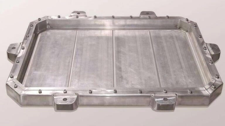
Electric vehicle motor housings are designed to be extremely lightweight. Consequently, the cast aluminum walls are often very thin, typically ranging between 3mm and 5mm.
When a cutting tool engages these thin walls, it generates mechanical forces. Standard tools often produce high radial forces, pushing directly outward against the wall. Because the wall is thin, it bends or deflects away from the cutting tool. Imagine using a blunt boring bar to open up a thin brass tube on a manual lathe. Instead of cutting cleanly, the dull tool pushes the brass outward, causing an uneven and tapered cut.
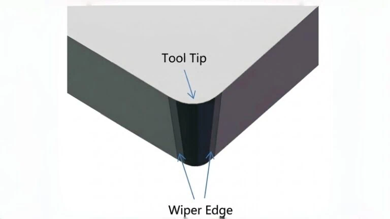
Custom PCD tools solve this problem through optimized edge geometry. Tool designers create PCD inserts with a high positive rake angle and microscopically sharp cutting edges. This specific geometry shears the aluminum cleanly rather than pushing it. The cutting action shifts from radial pressure to axial pressure, directing the cutting energy downward into the thicker, stiffer base of the housing and preventing the thin walls from flexing.
Suppressing Chatter in Deep Stator Bores
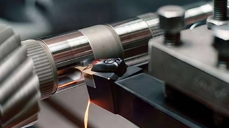
The stator bore is the large central cavity of the motor housing. It is typically very deep. Machining a deep bore requires a long tool, which creates a large length-to-diameter (L/D) ratio. In machining, a long tool hanging out of a spindle acts just like a tuning fork. When the tool touches the metal, it naturally starts to vibrate. This harmful vibration is known as chatter7.
Chatter is disastrous for EV motor housings. It leaves visible, rippled marks on the machined surface and quickly fractures the brittle cutting edge of the PCD tool. To suppress chatter, engineers use several specific design techniques.
Unequal Flute Spacing
One highly effective method for roughing or semi-finishing passes is unequal flute spacing. Standard cutting tools usually have cutting edges spaced evenly apart, creating a rhythmic harmonic frequency that quickly builds into violent chatter. Conversely, placing the PCD flutes at staggered, unequal angles breaks that harmonic rhythm instantly.
Vibration-Damping Tool Bodies
Another method involves the tool body material itself. Instead of standard steel, custom deep-boring tools often use heavy metal alloys or solid carbide bodies, which are much stiffer and resist bending. In highly severe cases, these tools include internal damping mechanisms to absorb the vibrational energy before it reaches the cutting edge.
| Tool Body Design Strategy | Chatter Risk | Expected Surface Finish Quality |
|---|---|---|
| Standard Steel Body (Even Flutes) | High | Poor (Visible chatter marks and poor Ra) |
| Solid Carbide Body (Unequal Flutes) | Low | Excellent (Smooth finish, tight tolerances) |
| Heavy Metal with Internal Dampers | Very Low | Superior (Consistently meets strict Ra specs) |
Achieving Strict Concentricity and Cylindricity Tolerances
The electric motor rotor spins inside the stator bore at extremely high speeds. Therefore, the bore must be a perfect cylinder. If the bore is slightly oval, or if it tapers at the bottom, the motor will lose efficiency or fail completely. This application requires strict concentricity and cylindricity tolerances, often tighter than 20 microns.
Vibration and wall deflection make these tight tolerances impossible to achieve with standard single-point boring setups. To stabilize the cutting process, custom PCD tools rely on a perfectly balanced mechanical design.
The Role of Symmetrical Multi-Edge Boring
Standard single-point boring tools exert unopposed radial pressure, physically pushing the thin aluminum wall outward during the cut. When the tool retracts, the wall springs back, instantly ruining the cylindricity.
To counteract this, custom PCD finishing tools are engineered with multiple cutting edges (typically four, six, or eight flutes) spaced symmetrically around the tool body. As the tool rotates, the radial cutting forces generated by each edge perfectly cancel each other out. Because these forces are balanced internally within the tool geometry, there is zero net pressure pushing against the fragile housing wall.
Combined with micron-adjustable PCD cartridges, this balanced cutting action ensures the hole remains perfectly round from top to bottom. In a recent industry case study involving a complex aluminum stator housing, switching to a symmetrical multi-edge PCD boring tool improved cylindricity from a failing 35 microns down to just 12 microns, eliminating the dimensional scrap rate entirely.
Accelerating Production with Custom Combination PCD Tools
Custom combination PCD tools accelerate production by consolidating multiple machining steps into a single pass. Manufacturers merge operations like boring, facing, and chamfering onto one unified tool body. This strategy directly eliminates time-consuming tool changes and dramatically shortens the total cycle time per part.
Merging Boring, Facing, and Chamfering Operations
In high-volume manufacturing, efficiency relies on continuous cutting. Custom combination tools achieve this by utilizing a “step” design. A single tool body holds multiple Polycrystalline Diamond (PCD) cutting edges at different diameters and heights.
Think of a combination tool like a multi-spindle automatic lathe. On a standard lathe, a single cutting tool finishes one feature before moving to the next. On a multi-spindle machine, several tools engage the metal simultaneously to save time. A combination tool applies this exact same simultaneous cutting principle, but it uses just one CNC milling spindle.
As the machine feeds the custom tool into the EV motor housing, the front edges bore the main diameter. Simultaneously, the middle cutting edges chamfer the inner lip. Finally, the top edges face the outer surface. The machine performs three distinct operations in one single downward stroke.
“Combining operations reduces the total cutting distance the machine spindle must travel.”
However, combining these cuts increases the total torque load on the machine. Feed rates and cutting speeds for step tools depend heavily on the specific aluminum grade and your machine’s horsepower. Always verify maximum load limits with your tooling supplier before implementation to prevent spindle stalls.
Impact on Cost Per Part and Overall ROI
Many shop managers hesitate to purchase custom PCD tools due to the high initial price tag. A single custom tool easily costs several times more than a standard solid carbide end mill. Yet, evaluating the overall Return on Investment (ROI)8 paints a completely different picture.
The true value lies in the drastically reduced cost per part9. Custom PCD tools cut cycle times by eliminating tool changes and merging tool paths. Furthermore, PCD is significantly harder than carbide, resisting the abrasive wear of high-silicon aluminum exceptionally well.
While a solid carbide tool might process 2,000 parts before failing, a custom PCD tool often processes 50,000 to 100,000 parts. This massive increase in tool life means the production line stays running.
| Production Metric | Standard Carbide Setup | Custom Combination PCD |
|---|---|---|
| Tools Required | 3 Separate Tools | 1 Multi-Step Tool |
| Tool Changes per Cycle | 3 | 0 |
| Estimated Tool Life | ~2,000 parts | 50,000+ parts |
| Cost Per Part | High (Labor + frequent replacements) | Very Low (High upfront, massive output) |
Ultimately, the combination of zero tool changes and extended tool life guarantees a rapid ROI for high-volume EV housing projects.
Lowering Machine Spindle Wear and Setup Downtime
Accelerating production is not just about making chips faster. It is also about protecting your CNC equipment and minimizing offline delays. Using combination tools directly reduces the physical strain on your machine tool.
Every time a CNC machine changes a tool, the automatic tool changer (ATC) arm swings. Simultaneously, the spindle drawbar actuates to release and grip the tool holder. In a sequential setup, a machine might perform thousands of these mechanical cycles every single day. By merging three tools into one, you instantly eliminate 66% of those mechanical cycles. Consequently, you significantly reduce wear and tear on the spindle drawbar and the ATC mechanism.
Furthermore, custom tools lower setup downtime. Measuring and qualifying three separate standard tools takes time. In contrast, an operator only needs to load and measure one combination tool. If the tool is preset offline using a tool presetter, the spindle downtime drops to nearly zero, allowing the machine to spend more hours per shift actually producing housings.
Key Considerations When Engineering a Custom Tooling Strategy
Engineering a successful custom tooling strategy requires precise alignment between the tool’s physical dimensions and the specific kinematic limits of the CNC machine. Furthermore, engineers must prioritize highly efficient chip evacuation systems, typically achieved by designing precise through-tool coolant channels that flush sticky aluminum chips away from the cutting zone instantly.
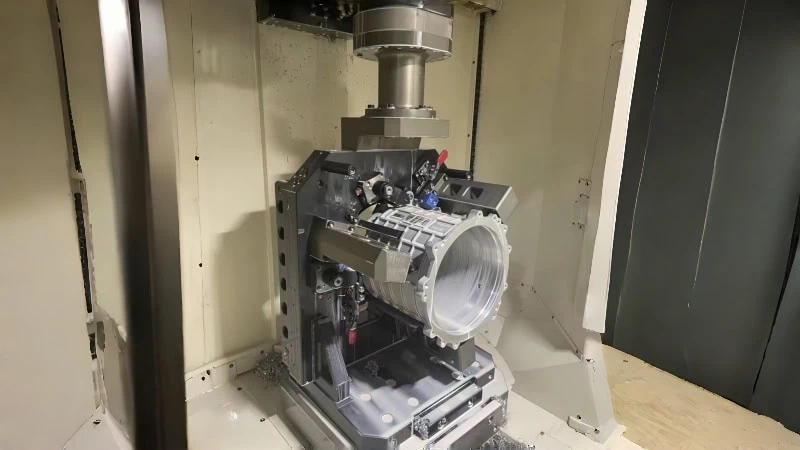
Aligning Tool Design with Machine Kinematics
A custom tool is only effective if your machine can drive it properly. Machine kinematics refers to the physical capabilities and operating limits of your CNC equipment. Therefore, you must evaluate available spindle horsepower, maximum torque, and the physical constraints of the tool magazine.
Are you trying to run a massive multi-step tool on a lightweight machine? This scenario is exactly like trying to run a heavy 8-inch face mill on a small, low-horsepower spindle. The machine simply lacks the necessary rigidity. Consequently, the spindle will stall, or the internal bearings will fail prematurely.
Managing Weight Limits and Tool Changers
Custom combination tools are often quite large and heavy. Every Automatic Tool Changer (ATC) has a strict maximum weight capacity. If a custom tool is too heavy, the ATC arm will drop it. Alternatively, it will severely damage the changer mechanism over time. Because CNC torque curves and ATC capacities vary dramatically between different machine models, verify the exact kinematic limits with your machine builder before finalizing a heavy tool design.
Selecting the Right Spindle Connection
The connection interface between the tool and the spindle is vital. For large EV motor housing tools, standard steep-taper holders often lack stability. Instead, engineers strongly prefer HSK-A63 or HSK-A10010 tool holders. These specific holders provide simultaneous dual-contact on both the taper and the flange, guaranteeing maximum rigidity when driving heavy custom tools.
The Importance of Through-Tool Coolant and Chip Evacuation
Machining aluminum creates a very specific problem. The material is soft and sticky. When the aluminum gets hot, it melts and sticks directly to the cutting edge. This specific problem is called Built-Up Edge (BUE)11. To prevent BUE, you must control the temperature and evacuate the chips immediately.
Have you ever tried to clear packed chips from a deep pocket using only an external coolant hose? It simply does not work reliably. External flood coolant often bounces off the spinning tool body. It rarely reaches the actual cutting zone deep inside a stator bore.
High-Pressure Internal Coolant Delivery
The absolute best solution is high-pressure through-tool coolant. Custom PCD tools feature internal channels drilled directly through the solid tool body. These precise channels must exit directly in front of the PCD cutting edge, aiming perfectly at the rake face and the shear zone.
Consequently, they blast high-pressure fluid exactly where the cutting action happens and the chips are formed. This focused stream physically severs the chips from the root and flushes them away instantly. It prevents the tool from re-cutting old aluminum chips and starves the process of the heat necessary to form Built-Up Edge. Re-cutting chips is disastrous because it will instantly score the machined surface and ruin strict dimensional tolerances.
| Coolant Delivery Method | Chip Evacuation Efficiency | Risk of Built-Up Edge (BUE) | Ideal for Deep EV Bores? |
|---|---|---|---|
| External Flood Coolant | Poor (Fluid blocked by tool) | High | No |
| Standard Through-Tool (Low Pressure) | Moderate | Medium | No |
| High-Pressure Through-Tool (70+ Bar) | Excellent (Chips flushed instantly) | Very Low | Yes |
Ultimately, designing precise coolant exits is just as important as designing the cutting edge itself. Efficient chip evacuation ensures consistent part quality and protects your costly custom tool from sudden catastrophic failure.
Conclusion
Standard cutting methods can no longer keep pace with the demands of modern electric vehicle production. The abrasive nature of high-silicon aluminum and the strict dimensional requirements of thin-walled components push solid carbide tools past their limits. By upgrading to custom combination PCD tools, manufacturers eliminate redundant tool changes, suppress harmful vibrations, and extend tool life exponentially. Ultimately, investing in a carefully engineered custom tooling strategy—one that respects the physics of pre-cast HPDC parts and leverages balanced, multi-edge geometries—is the most reliable way to maximize efficiency, protect machine assets, and significantly lower the cost per part in EV motor housing machining.
References
- custom combination Polycrystalline Diamond (PCD)1 – ZYDiamondTools product page detailing the capabilities and applications of custom PCD combination tooling.
- Standard solid carbide tools2 – An article comparing the fundamental differences and performance limits between PCD and traditional carbide cutting tools.
- aluminum alloys3 – Wikipedia article detailing the metallurgical properties, compositions, and applications of various aluminum alloys.
- High-Pressure Die Casting (HPDC)4 – ScienceDirect topic page explaining the High-Pressure Die Casting manufacturing process and its technical considerations.
- high-silicon aluminum5 – ZYDiamondTools case studies examining the specific challenges of machining high-silicon aluminum alloys and the effective PCD solutions.
- rough boring tool6 – An in-depth guide on the critical differences and tooling selection between rough boring and finish boring operations.
- chatter7 – Wikipedia article explaining the mechanics, causes, and effects of machining vibrations (chatter).
- Return on Investment (ROI)8 – Investopedia page providing a clear definition and calculation method for Return on Investment in business and capital expenses.
- cost per part9 – A guide explaining Total Cost of Ownership (TCO) in manufacturing and how advanced tooling reduces the true cost per part.
- HSK-A63 or HSK-A10010 – Wikipedia article covering various machine tool tapers, including the robust Hollow Shank Tooling (HSK) standard.
- Built-Up Edge (BUE)11 – Wikipedia article detailing the formation of Built-Up Edge during machining and its detrimental effects on surface finish and tool life.