-
Whatsapp: +86 13526572721
-
Email: info@zydiamondtools.com
-
Address: AUX Industrial Park, Zhengzhou City, Henan Province, China
-
Whatsapp: +86 13526572721
-
Email: info@zydiamondtools.com
-
Address: AUX Industrial Park, Zhengzhou City, Henan Province, China

Mastering PCD Countersinking for aerospace Composites: Advanced Techniques for Optimal Performance and Hole Quality

When it comes to working with advanced aerospace composites, how can you truly master PCD countersinking to achieve the best possible performance and ensure flawless hole quality?
Mastering PCD countersinking for aerospace composites involves a comprehensive approach, starting with understanding how specialized PCD tool designs address key machining challenges. It then requires carefully selecting and customizing tools for demanding applications, including aligning specs with material standards and considering custom geometries. Finally, optimizing the actual machining process through parameter adjustments, robust setups, defect troubleshooting, and diligent tool management is crucial for achieving optimal performance and hole quality.
Understanding How PCD Countersink Designs Solve Key aerospace Composite Issues
So, how exactly do the specific designs of PCD countersinks tackle the tough challenges encountered when machining aerospace composites?
PCD countersink designs conquer critical aerospace composite machining problems through several smart features. Optimized cutting edge shapes prevent material damage like delamination. Specific PCD grades stand up to tough, abrasive composite layers. Efficient flute designs clear away chips and manage heat, which is vital for precise, high-tolerance holes. Furthermore, specialized tool designs are available for modern automated aerospace manufacturing.
Aerospace manufacturing relies heavily on composite materials like Carbon Fiber Reinforced Polymers (CFRP). While these materials are incredibly strong and lightweight, they bring unique machining challenges. Thankfully, Polycrystalline Diamond (PCD) countersink drills, such as these PCD Countersink Drills for Composites1, are specifically engineered to address these. Let’s explore how their design features make a significant difference.
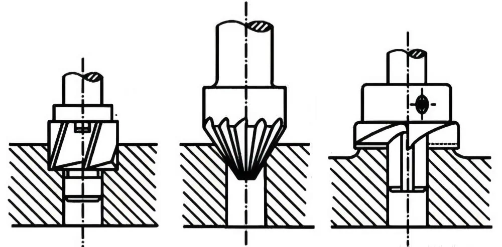
Edge Geometries for Delamination-Free Aerospace Countersinking
One of the biggest headaches when working with aerospace composites is delamination2. This is where the layers of the composite material separate, or fibers get pulled out, especially at the entry or exit of a hole. This can severely weaken the part, which is a major concern for aircraft safety and performance. So, how do PCD countersinks help?
It’s all about the shape and sharpness of the cutting edges. PCD tools can be ground to incredibly sharp and precise edge geometries.
- Optimized Rake Angles: The rake angle is the angle of the cutting face relative to the workpiece.
- For many aerospace composites, a positive rake angle helps to “shear” the fibers cleanly, much like a sharp knife slicing through vegetables. This reduces the cutting forces, minimizing stress on the material and thereby reducing the risk of delamination and fiber pull-out.
- In some specific cases, a neutral or slightly negative rake angle might be used, particularly for highly abrasive composites or to improve edge strength, but positive rakes are generally preferred for achieving a clean cut in standard CFRP.
- Sharp Cutting Edges: PCD’s hardness allows for exceptionally sharp and durable cutting edges. A sharp edge cleanly severs composite fibers instead of pushing them aside or tearing them, which is a common cause of defects with duller tools. Think of trying to cut fabric with dull scissors versus sharp ones – the difference is clear! Understanding the key properties of PCD3 clarifies why it maintains sharpness.
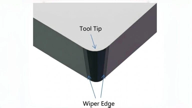
- Specific Point and Helix Angles: The overall geometry of the countersink’s point and the helix angle of its flutes (if applicable to the countersinking portion) are also carefully designed. These features work together to ensure a smooth entry into the material and to guide the cutting forces in a way that promotes clean shearing. For instance, a higher helix angle can help lift chips out more effectively, but the primary cutting action for the countersink’s chamfer is often more about the direct engagement of its angled cutting faces.
The goal is always a clean, crisp cut that maintains the structural integrity of the composite. For example, in manufacturing aircraft wing spars or fuselage panels, achieving delamination-free holes is critical for ensuring the long-term durability and safety of these components. The specific “best” geometry can sometimes depend on the exact composite layup (e.g., unidirectional fibers vs. woven fabric) and the resin system used. Therefore, it’s a good practice to consult with the tool supplier, as they can recommend edge geometries optimized for specific aerospace materials based on extensive testing and experience.
PCD Grade Selection for Abrasive Aerospace Laminates & Stacks
Aerospace composites, especially those reinforced with carbon or boron fibers, are notoriously abrasive. Imagine trying to cut sandpaper with a regular steel knife – the knife would dull very quickly! This is similar to what happens when machining these advanced materials. Rapid tool wear not only leads to frequent tool changes and higher costs but also results in poor hole quality as the tool dulls.
PCD is one of the hardest materials available, making it exceptionally resistant to this abrasive wear. However, not all PCD is the same. There are different “grades” of PCD, and choosing the right one is crucial. For context, it’s useful to understand the difference between PCD and carbide tools4, as carbide is often the alternative that PCD outperforms in these applications.
What are PCD Grades?
PCD grades are typically defined by their diamond grain size and, to some extent, the metallic binder content.
- Finer Grain Sizes (e.g., 2-5 µm): These grades generally offer better edge sharpness and can produce a superior surface finish. They are often preferred for finishing operations or when machining less abrasive composites, or composites where the absolute finest finish is paramount.
- Medium Grain Sizes (e.g., 10-25 µm): These grades provide a good balance of wear resistance and toughness. They are versatile and widely used for many aerospace composite applications.
- Coarser Grain Sizes (e.g., 30-50 µm+): These grades offer the highest abrasion resistance and toughness, making them suitable for highly abrasive composites, interrupted cuts, or when machining stacked materials (like CFRP/aluminum or CFRP/titanium, though our focus here is primarily composites). They can withstand more impact.
The selection directly impacts tool life and performance. For instance, when countersinking a thick carbon fiber laminate used in an aircraft’s primary structure, a medium to coarser PCD grade might be selected to ensure extended tool life despite the material’s high abrasiveness. Conversely, for a composite with a higher resin content and less abrasive fibers where surface finish is critical, a finer PCD grade might be chosen.
Important Note: The exact PCD grade designations and their optimal applications can vary between tool manufacturers. It is always advisable to discuss your specific aerospace material (including fiber type, resin, and any stacked configuration) and machining conditions with your PCD tool supplier to select the most effective grade.
Flute Design & Cooling for High-Tolerance Aerospace Needs
Aerospace components demand incredibly tight tolerances. A countersunk hole for a fastener must be perfectly sized and shaped to ensure proper load distribution and joint integrity. Two major enemies of tight tolerances in composite machining are poor chip evacuation and excessive heat.
- Why Chip Evacuation is Critical: Composite chips, especially from CFRP, can be powdery or small and sharp. If these chips are not efficiently removed from the cutting zone, they can be re-cut, leading to increased friction, heat, and a poor surface finish. Packed chips can also exert extra pressure on the tool and workpiece, potentially causing defects or dimensional inaccuracies.
- PCD countersink flutes are designed to address this. They can be:
- Polished: Highly polished flutes reduce friction, allowing chips to slide out more easily.
- Optimized Shape and Number: The number of flutes (e.g., one, two, or three) and their geometric shape (e.g., depth, helix if it’s a drilling countersink) are carefully balanced. Fewer flutes can offer more space for chip evacuation, while more flutes can provide better stability and finish in some cases. For pure countersinking (chamfering an existing hole), the flute design primarily ensures the cut material is directed away from the finished surface.
- PCD countersink flutes are designed to address this. They can be:
- The Role of Cooling in Precision Machining: Machining generates heat. Excessive heat can cause thermal expansion5 of the tool and workpiece, leading to dimensional inaccuracies. It can also damage the composite material itself, potentially degrading the resin matrix or causing thermal stress.
- While PCD is excellent at conducting heat away from the cutting edge, effective flute design helps remove hot chips, which are a primary source of heat transfer to the workpiece.
- Some advanced PCD countersinking tools, especially those used in high-volume automated systems, may even incorporate internal coolant channels. These channels deliver coolant (like chilled air or a fine mist) directly to the cutting zone, providing highly effective cooling and chip removal. This is particularly beneficial in maintaining the extremely tight tolerances required for aerospace fasteners, ensuring a perfect fit and long-term joint reliability.
For example, when producing the thousands of countersunk holes for rivets in an aircraft fuselage panel, maintaining dimensional consistency from the first hole to the last is crucial. Efficient flute design and appropriate thermal management are key to achieving this.
Specialized PCD Designs for Automated Aerospace Countersinking
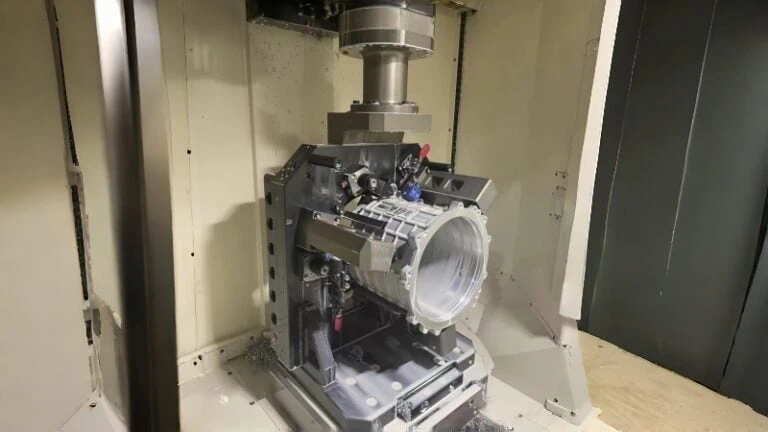
The aerospace industry is increasingly adopting automation in manufacturing, including robotic systems for drilling and countersinking operations on large structures like wings and fuselages. These automated systems demand tools that are not only high-performing but also exceptionally reliable and consistent.
PCD countersinks for these applications often feature specialized designs:
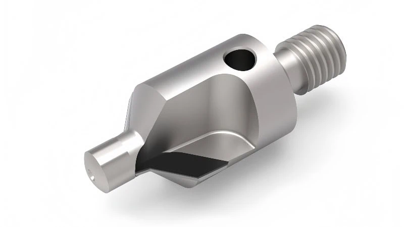
- Integral Shank Designs: Instead of a separate pilot or a modular design, many PCD countersinks for automation have an integral (solid) shank. This construction offers superior rigidity and concentricity (meaning the tool rotates perfectly on its axis). Better concentricity is vital for producing accurate hole locations and geometries, which is a must in automated systems where manual adjustments are minimal.
- Robust Pilot Designs: If a piloted countersink is used (where a pilot guide fits into a pre-drilled hole), the pilot needs to be extremely durable and precise to withstand the rigors of automated, high-volume use without wear affecting accuracy.
- Compatibility with Automated Tool Changers: These tools are often designed with specific shank styles (e.g., HSK, SK, or other standardized tapers) that are compatible with the automatic tool changers found in modern CNC machining centers and robotic end-effectors. This allows for seamless tool swaps and continuous operation.
- Enhanced Durability for Unattended Operation: The overall construction, including the braze joint quality (if the PCD tip is brazed onto a carbide body), must be exceptionally robust to ensure long periods of reliable, unattended operation. Any premature tool failure in an automated cell can lead to significant downtime and production losses.
Consider the automated assembly lines for modern passenger jets. Robots perform countless drilling and countersinking operations. The PCD tools they use must deliver identical, high-quality results every time, often for thousands of cycles before needing replacement. Specialized PCD countersink designs are therefore fundamental to the efficiency and precision of modern aerospace manufacturing.
Selecting and Customizing PCD Countersinks for Demanding aerospace Applications
So, when faced with demanding aerospace applications, how does one effectively select or even customize the perfect PCD countersink?
Selecting and customizing PCD countersinks for demanding aerospace applications involves a detailed approach. Key strategies include meticulously aligning tool specifications with stringent aerospace material standards and developing custom tool designs for complex part geometries. Engineers also consider non-standard angles to meet specific joint strength or sealing requirements. Furthermore, a rigorous tool qualification process within certified manufacturing environments is essential to ensure reliability and performance.
Choosing the right PCD countersink for aerospace isn’t just about picking one off a shelf. Aerospace applications often involve unique challenges, from exotic materials to intricate designs and the highest safety standards. This means the selection process, and sometimes even the tool design itself, needs careful thought, often exploring if PCD tools are the optimal choice6 for the specific composite.
Aligning Tool Specs with Aerospace Material Standards
Aerospace materials are at the cutting edge of technology. They include various grades of Carbon Fiber Reinforced Polymers (CFRP), Glass Fiber Reinforced Polymers (GFRP), and sometimes complex hybrid stacks. Each material has unique properties and machining characteristics. Therefore, it’s vital to align the PCD countersink’s specifications with these standards.
- Understanding Material Designations: Aerospace often uses specific material designations (like those from SAE AMS – Aerospace Material Specifications, or specific OEM proprietary specs). These standards define the fiber type, resin system, cure cycle, and sometimes even the fiber volume ratio. These details significantly affect how the material will behave when machined. For example, a CFRP with high-modulus carbon fibers will be more abrasive than one with standard-modulus fibers. Similarly, toughened resin systems, designed to resist impact, can machine differently than standard epoxy resins.
- Matching PCD Grade and Geometry:
- Different PCD grades (defined by diamond grain size) offer varying levels of wear resistance and edge sharpness. For highly abrasive aerospace composites, a tougher, coarser PCD grade might be necessary to ensure reasonable tool life. For composites where achieving an exceptionally fine surface finish is paramount to prevent micro-cracking, a finer PCD grade could be selected.
- The tool’s cutting geometry (rake angles, clearance angles, and edge preparation) must also be compatible. Some aerospace composites are prone to splintering or fuzzing with aggressive geometries, while others require such geometries for clean cutting.
- Considering Stacked Materials: Aerospace components frequently involve stacks of different materials, such as layers of CFRP with varying fiber orientations, or CFRP co-cured or bonded with metallic foils (e.g., for lightning strike protection). Selecting a PCD countersink that can effectively machine these dissimilar layers without damaging any of them is a key challenge. This often requires a compromise in PCD grade and geometry that performs adequately across all materials in the stack.
Key Takeaway: Always start with a thorough understanding of the exact aerospace material specification. Tool suppliers often have extensive databases and experience in matching their PCD tool specifications to these specific materials. Providing them with detailed material information is crucial for receiving the best recommendation. Remember that slight variations in material composition or supplier can impact machinability, so clear communication with both your material and tool supplier is essential.
Custom PCD Countersinks for Complex Aerospace Geometries
Standard, off-the-shelf PCD countersinks are great for many applications. However, aerospace components often feature complex shapes and geometries where standard tools simply won’t fit or perform optimally. This is where custom PCD countersinks (illustrating customization capabilities sometimes detailed alongside custom PCD forming tools) become indispensable.
When might you need a custom solution?
- Countersinking on Curved or Contoured Surfaces: Aircraft skins, wing leading edges, and engine nacelles often have complex curvatures. A standard countersink might not sit correctly or produce an accurate chamfer on such surfaces. Custom tools can be designed with specific pilot geometries or overall shapes to accommodate these contours. For instance, a countersink might need a spherical pilot or a specially angled body to properly engage a curved surface.
- Restricted Access Areas: Machining inside deep cavities, around internal structures, or in tight corners is common in aerospace assembly. Standard tools might be too bulky. Custom PCD countersinks can be made with extended shanks, reduced neck diameters, or specific overall lengths to reach these difficult spots.
- Unique Fastener Head Profiles: While many aerospace fasteners use standard countersink angles (like 100° or 130°), some specialized fasteners may require non-standard angles or even complex, multi-angle chamfer profiles to ensure optimal load transfer or sealing. Custom PCD tools can be ground to create these precise, unique forms.
- Combined Operations: Sometimes, a custom tool can be designed to perform multiple operations in one pass, such as drilling, countersinking, and spot-facing, to save time and improve concentricity in high-volume aerospace production.
The process of developing a custom PCD countersink typically involves close collaboration between your engineering team and the tool supplier. This often includes:
- Providing detailed drawings or CAD models of the aerospace part and the specific feature to be machined.
- Defining the exact material specifications.
- Discussing the machining conditions and equipment to be used.
- The tool supplier then designs the custom PCD countersink, often providing a drawing or model for approval before manufacturing.
While custom tools may have a higher upfront cost and longer lead times, the benefits in terms of part quality, reduced scrap, and improved assembly efficiency in complex aerospace applications often outweigh these factors.
Non-Standard Angles for Aerospace Joint Strength & Sealing
The angle of the countersink is a critical feature. For aerospace applications, it’s not just about making the fastener head sit flush; it’s about ensuring the structural integrity of the joint and, in many cases, providing an effective seal.
- Common Aerospace Angles: Standard angles like 100° are very common for many aerospace flush-head fasteners (e.g., MS20426 / AN426 series screws). 130° is another angle sometimes encountered.
- Why Non-Standard Angles?
- Optimized Stress Distribution: For certain critical joints subjected to high loads or fatigue cycles, engineers might specify a non-standard countersink angle. This can help to distribute stress more evenly between the fastener and the composite material, potentially improving the fatigue life of the joint. For example, a slightly shallower or deeper angle than standard might be calculated through Finite Element Analysis (FEA)7 to be optimal for a specific loading condition and material combination.
- Sealing Requirements: In applications where a fuel-tight or environmentally sealed joint is necessary (e.g., in fuel tanks or pressurized fuselage sections), the countersink angle and depth are critical for ensuring proper compression of sealant applied under the fastener head. A non-standard angle might be chosen to create the ideal sealant reservoir volume and squeeze-out characteristics.
- Specific Fastener Designs: Some proprietary or specialized aerospace fasteners are designed to work with unique, non-standard countersink angles to achieve their intended performance characteristics.
Important Consideration: Using a non-standard countersink angle means that the corresponding fasteners must also be designed or selected to match that angle precisely. Mismatched angles can lead to improper fastener seating, reduced joint strength, and potential damage to the composite material. Any deviation from standard angles should be based on thorough engineering analysis and testing. Tool suppliers can manufacture PCD countersinks to virtually any specified angle, but it’s crucial that this specification is accurate and well-defined. Always verify the required angle from the engineering drawings or fastener specifications.
Tool Qualification in Certified Aerospace Manufacturing
The aerospace industry operates under extremely strict quality control and certification standards (e.g., AS9100, which is the aerospace quality management system standard). This means that not only the final parts but also the processes and tools used to make them often need to be qualified. Introducing a new PCD countersink, especially a custom one or one for a critical application, typically involves a formal qualification process.
What does tool qualification entail?
- First Article Inspection (FAI): The initial parts produced with the new PCD countersink will undergo rigorous inspection. This verifies that the tool is producing holes that meet all dimensional specifications (diameter, depth, angle, surface finish) as per the engineering drawings.
- Machining Trials & Capability Studies: The tool may be subjected to machining trials to assess its performance under representative production conditions. This can involve machining a set number of holes and evaluating:
- Consistency: Does the tool produce consistent results from the first hole to the last?
- Tool Life: How many acceptable holes can be produced before the tool wears beyond acceptable limits? This helps in establishing tool change intervals.
- Process Capability (Cpk): Statistical analysis might be used to determine if the process, using that specific tool, is capable of consistently meeting the required tolerances.
- Documentation: All aspects of the tool qualification process, including tool specifications, machining parameters used, inspection results, and any process adjustments, are meticulously documented. This documentation is crucial for traceability and quality assurance, forming part of the overall manufacturing record for the aerospace component.
Why is this crucial for aerospace? The failure of a single fastener joint can have catastrophic consequences. Tool qualification provides confidence that the chosen PCD countersink, when used correctly, will consistently produce holes that meet the demanding safety and reliability standards of the aerospace industry. It helps to de-risk the manufacturing process and ensure that every component performs as designed. This formal approval step is a hallmark of the disciplined engineering environment in aerospace.
Optimizing the PCD Countersinking Process for aerospace Hole Quality & Reliability
Once you have the right PCD countersink, what are the best strategies to truly optimize the actual machining process for that perfect aerospace-grade hole quality and unwavering reliability?
Optimizing the PCD countersinking process for aerospace hole quality and reliability involves several key actions. This includes advanced parameter optimization tailored to specific composites, and careful management of clamping, fixturing, and machine dynamics. Additionally, effective troubleshooting of common defects and robust tool wear management with process control are crucial for consistent, high-standard results.
Having the ideal PCD countersink is a great start. However, achieving consistently flawless results in demanding aerospace applications requires fine-tuning the entire machining process. From the speeds and feeds you use to how you hold the part, every detail matters. Let’s dive into how to make your PCD countersinking operations truly shine.
Advanced Parameter Optimization for Specific Aerospace Composites
Think of machining parameters – like cutting speed and feed rate – as the recipe for a perfect hole. Just as a chef adjusts cooking times and temperatures for different ingredients, machinists must adjust parameters for different aerospace composites. What works for one type of Carbon Fiber Reinforced Polymer (CFRP) might not be ideal for another with a different fiber type, resin, or layup (the way the layers are stacked).
- Cutting Speed (RPM): This is how fast the PCD countersink spins.
- For PCD tools in composites, speeds are generally high compared to machining metals. This helps achieve a clean shearing action.
- However, too high a speed can generate excessive heat, potentially damaging the resin in the composite or accelerating tool wear.
- Feed Rate (mm/rev or inch/rev): This is how quickly the tool advances into the material per revolution.
- A feed rate that’s too low can cause rubbing, leading to heat and rapid tool wear.
- A feed rate that’s too high can exert excessive force on the composite, increasing the risk of delamination, fiber pull-out, or even tool breakage.
- Finding the Sweet Spot: The goal is to find a “machining window” – a range of speeds and feeds that produces excellent hole quality with good tool life. This often involves:
- Starting with supplier recommendations: PCD tool manufacturers usually provide starting parameters for different composite families.
- Methodical Testing: Small, incremental adjustments and careful observation of the results (hole quality, chip formation, tool wear) are key. For example, you might start with a recommended speed and then test slightly higher and lower feed rates to see the impact on exit-side delamination or surface finish.
- Considering the Composite:
- Highly Abrasive Composites: Might require slightly lower cutting speeds to manage wear.
- Tough Resins: May need adjusted feed rates to avoid excessive cutting forces.
- Unidirectional vs. Woven Fabrics: The direction of fibers relative to the cutting edge can influence the optimal parameters.
Important Note: Recommended cutting speeds and feed rates for PCD countersinks in aerospace composites can vary significantly based on the specific PCD tool geometry, the exact composite material properties, the machine tool’s capability, and the rigidity of the setup. Always use supplier data as a starting point and conduct controlled tests to optimize for your specific application. Documenting successful parameters for different material batches or components is a vital part of aerospace process control.
Impact of Clamping, Fixturing & Machine Dynamics on Accuracy
Imagine trying to write neatly on a flimsy piece of paper balanced on your knee – it wouldn’t be easy! Similarly, how an aerospace composite part is held (clamped and fixtured) and the condition of the machine tool itself play a massive role in achieving accurate countersunk holes.
- Secure Clamping: Aerospace composite parts, especially large, thin panels, can be flexible.
- The part must be clamped securely to prevent movement or vibration during machining. Any movement can lead to inaccurate hole location, inconsistent countersink depth, or even tool damage.
- Clamping pressure should be sufficient but not excessive, as too much force could distort or damage the composite part. Specialized vacuum fixtures or low-profile clamping systems are often used for aerospace composites.
- Rigid Fixturing: The fixture that holds the part must be rigid and stable.
- Any flex or vibration in the fixture will be transferred to the cutting process, negatively impacting hole quality.
- Fixtures should be designed to support the area being machined as closely as possible to minimize deflection. For instance, when countersinking holes in a large aircraft skin panel, the fixture might include localized supports directly beneath the hole locations.
- Machine Tool Dynamics: The condition and capabilities of the CNC machine or robotic system are critical.
- Spindle Runout: The spindle must rotate the PCD countersink true, with minimal wobble (runout). Excessive runout leads to oversized or irregularly shaped countersinks and accelerates tool wear. Aerospace standards often demand very low spindle runout.
- Machine Stiffness & Accuracy: The machine must be stiff enough to withstand cutting forces without deflecting. The machine’s axes must also move accurately and repeatably to ensure holes are in the correct location and countersinks are at the correct depth. Regular machine calibration and maintenance are essential.
In aerospace, where precision is paramount, a robust setup is non-negotiable. For example, when an automated robotic system is countersinking thousands of holes on a wing assembly, any instability in the part holding or robot arm can lead to a cascade of out-of-tolerance features, potentially requiring costly rework or scrap.
Troubleshooting Common Aerospace Countersinking Defects
Even with the best tools and careful setup, machining issues can sometimes arise. Quickly identifying and addressing these defects is crucial in aerospace to maintain quality and avoid scrap. Here are some common defects when countersinking composites and potential process-related causes:
| Defect | Potential Process-Related Causes | Possible Corrective Actions (Process-Focused) |
|---|---|---|
| Delamination (Entry/Exit) | Feed rate too high; Dull tool (wear); Incorrect cutting parameters; Insufficient part support/backing; Vibration. | Reduce feed rate; Check/replace tool; Optimize speed/feed; Improve backing material/fixturing; Stiffen setup. |
| Fiber Pull-out / Fuzzing | Dull cutting edge; Incorrect cutting geometry for the material (wear makes it a process issue); Feed rate too high or too low; Wrong speed. | Check/replace tool; Adjust feed rate (often slightly lower helps); Optimize cutting speed. |
| Resin Smearing / Burning | Cutting speed too high; Feed rate too low (causing rubbing); Dull tool; Insufficient chip evacuation/cooling. | Reduce cutting speed; Increase feed rate; Replace tool; Improve chip removal (e.g., air blast, coolant if applicable). |
| Incorrect Angle / Depth / Diameter | Incorrect machine setup/programming; Tool wear affecting effective geometry; Part movement; Machine inaccuracy/deflection. | Verify program & tool offsets; Monitor tool wear & replace; Improve clamping/fixturing; Check machine calibration/stiffness. |
| Poor Surface Finish (in chamfer) | Dull tool; Vibration; Incorrect parameters (speed/feed balance); Chip recutting. | Replace/recondition tool; Stiffen setup, check machine dynamics; Optimize speed/feed; Improve chip evacuation. |
Remember, these are process-related causes. If problems persist after optimizing these aspects, you might need to revisit tool selection or even the fundamental tool design features. Systematic troubleshooting, often involving a “cause and effect” or “fishbone” diagram, can be very helpful in complex aerospace manufacturing environments.
Tool Wear Management & Process Control in Aerospace Production
PCD tools are incredibly wear-resistant, but they don’t last forever, especially when machining abrasive aerospace composites. Managing tool wear effectively is vital for maintaining consistent hole quality, preventing scrap, and controlling costs in high-volume aerospace production. The overall Total Cost of Ownership (TCO)8 of tooling is an important consideration.
- Monitoring Tool Wear: How do you know when a PCD countersink is worn?
- Visual Inspection: Regularly inspect the cutting edges for signs of chipping, rounding, or flank wear, often using magnification.
- Part Quality Checks: An increase in defects like delamination, fuzzing, or changes in surface finish can indicate a dulling tool. Dimensional checks of the countersunk hole (angle, diameter, depth) are also critical.
- Spindle Load Monitoring: On CNC machines, an increase in spindle load while cutting can signal that the tool is becoming dull and requiring more force.
- Acoustic Monitoring: Changes in the sound of the cutting process can sometimes indicate tool wear.
- Establishing Wear Criteria & Tool Change Schedules:
- Don’t wait for the tool to fail completely. Define acceptable wear limits based on experience and part quality requirements. For instance, a maximum flank wear land size (e.g., 0.15 mm) might be set.
- Based on typical wear rates for a specific application, establish predetermined tool change intervals (e.g., after a certain number of holes or machining hours). This proactive approach is common in aerospace to ensure consistent quality.
- Statistical Process Control (SPC): For critical aerospace components, SPC techniques can be used. This involves regularly measuring key features of the countersunk holes (like depth or diameter) and plotting them on control charts. This helps to monitor the process for stability and identify trends (like those caused by gradual tool wear) before out-of-tolerance parts are produced.
- PCD Tool Reconditioning: Many PCD countersinks can be reconditioned (re-sharpened or relapped) by specialized services. Learning about PCD tool sharpening9 can provide insight into this cost-saving measure, especially for expensive or custom PCD tools common in aerospace. It’s important to work with a reputable reconditioning service that understands the precise geometries required for aerospace applications.
Important Note: The rate of tool wear and optimal tool change intervals will depend heavily on the specific aerospace composite being machined, the cutting parameters used, and the efficiency of chip evacuation and cooling. It is crucial to collect data from your specific operations to establish effective tool wear management protocols. Some tool suppliers may also offer guidelines on expected tool life or wear characteristics for their PCD products in certain materials.
By diligently optimizing these process aspects, aerospace manufacturers can harness the full potential of PCD countersinking technology to produce high-quality, reliable components efficiently and consistently.
Conclusion
Mastering PCD countersinking for aerospace composites is a multifaceted endeavor that extends beyond simply choosing a hard cutting tool. It demands a thorough understanding of how specific PCD tool design features directly combat the unique machining challenges posed by these advanced materials. Furthermore, success hinges on a meticulous approach to selecting and, when necessary, customizing these tools to align perfectly with stringent aerospace material standards, complex component geometries, and specific joint requirements, all validated through rigorous qualification processes.
Ultimately, however, even the best-designed and most carefully selected tool requires an optimized machining process. This involves fine-tuning cutting parameters for each unique composite, ensuring absolute stability through robust clamping and fixturing, diligently troubleshooting any emergent defects, and implementing comprehensive tool wear management and process control strategies.
By integrating these advanced techniques—from intelligent tool design and selection to meticulous process optimization—aerospace manufacturers can consistently achieve superior hole quality, ensure unwavering reliability in critical components, and maximize the significant performance advantages offered by PCD tooling in the demanding world of aerospace composites. The pursuit of perfection in every countersunk hole is paramount, and a holistic understanding of these principles is key to achieving that goal.
References
- PCD Countersink Drills for Composites1 – Product page for PCD countersink drills specifically designed for CFRP/GFRP composite materials by ZYDiamondTools.
- Delamination2 – ScienceDirect topic page providing a scientific overview of delamination in materials science.
- Key Properties of PCD3 – ZYDiamondTools blog post explaining the fundamental properties of Polycrystalline Diamond, such as hardness, toughness, and wear resistance.
- Difference between PCD and Carbide Tools4 – An article from ZYDiamondTools comparing PCD and carbide cutting tools.
- Thermal Expansion5 – Wikipedia page explaining the concept and principles of thermal expansion.
- PCD Tools are the Optimal Choice6 – ZYDiamondTools article discussing the suitability of PCD tools for machining aerospace composites.
- Finite Element Analysis (FEA)7 – Ansys page explaining what Finite Element Analysis is, its importance, and how it works.
- Total Cost of Ownership (TCO)8 – ZYDiamondTools guide explaining the Total Cost of Ownership concept for superhard tooling and abrasives.
- PCD Tool Sharpening9 – ZYDiamondTools blog post on techniques and best practices for sharpening PCD and PCBN tools.