-
Whatsapp: +86 13526572721
-
Email: info@zydiamondtools.com
-
Address: AUX Industrial Park, Zhengzhou City, Henan Province, China
-
Whatsapp: +86 13526572721
-
Email: info@zydiamondtools.com
-
Address: AUX Industrial Park, Zhengzhou City, Henan Province, China

Are PCD Tools the Optimal Choice for Machining Your Aerospace Composites?

When it comes to machining tough aerospace composites, are PCD tools really the best way to go?
Yes, for many demanding aerospace composite applications, PCD (Polycrystalline Diamond) tools are often the optimal choice due to their exceptional wear resistance against abrasive fibers, enabling long tool life and consistent precision. Specialized PCD tool types like drills, routers, and countersinks address specific composite machining challenges, and maximizing their performance requires careful attention to cutting parameters, machine stability, and process monitoring.
Why is PCD Superior for Cutting Abrasive Aerospace Composites?
So, what makes PCD stand out when cutting tough aerospace composites?
PCD (Polycrystalline Diamond) offers unmatched hardness to resist the extreme abrasiveness of aerospace composites like CFRP, leading to significantly longer tool life. Furthermore, this exceptional wear resistance allows tools to maintain sharp cutting edges, ensuring consistent precision, tight tolerances, and superior surface finishes crucial for aerospace parts. Additionally, PCD effectively manages cutting heat, preventing thermal damage to sensitive composite materials.
Unmatched Wear Resistance Against Abrasive Fibers (Carbon, Glass)
Imagine trying to cut sandpaper with regular scissors – the scissors would get dull very quickly, right? Aerospace composites, particularly Carbon Fiber Reinforced Polymers (CFRP), are a bit like that. They contain incredibly hard and abrasive carbon or glass fibers embedded within a resin matrix. Consequently, when standard cutting tools made from materials like High-Speed Steel (HSS) or even solid carbide attempt to machine these composites, their cutting edges encounter tremendous friction and abrasion from these fibers. This leads to rapid wear, meaning the tool quickly becomes dull.
However, PCD is different. Think of it as making the scissor blades out of tiny, ultra-hard diamonds fused together. PCD stands for Polycrystalline Diamond, and it’s created by sintering1 together selected diamond particles at high pressure and temperature, often with a metallic binder. Diamond is the hardest known natural material on Earth. Therefore, tools with PCD cutting edges possess exceptional hardness, vastly exceeding that of carbide.
This extreme hardness allows PCD tools to effectively resist the abrasive nature of composite fibers. Instead of quickly dulling, the PCD edge maintains its sharpness for a considerably longer time. As a result, manufacturers experience significantly extended tool life. Naturally, actual results can vary based on machining conditions and the specific grade of materials, but the advantage is consistently substantial. This translates directly into fewer tool changes, reduced machine downtime, and more predictable manufacturing processes – all vital factors in the cost-conscious and high-stakes aerospace industry.

Maintaining Tight Tolerances and Superior Surface Finish Quality
Now, why is keeping a sharp edge so important beyond just lasting longer? Think about cutting with a very sharp knife versus a dull one. A sharp knife makes a clean, precise cut, while a dull knife tends to tear or push the material, leaving a rough edge. It’s similar with machining.
Because PCD tools resist wear and maintain their sharp cutting edges for extended periods, they cut more cleanly and consistently. This stability is crucial for aerospace components, which often require incredibly precise dimensions – what engineers call “tight tolerances2.” Parts for aircraft or spacecraft must fit together perfectly for safety and performance. A tool edge that doesn’t wear quickly ensures that every cut is accurate, maintaining these critical dimensions throughout long production runs.
Furthermore, a sharp, stable PCD edge shears the composite fibers cleanly rather than plucking or tearing them from the resin matrix. This action results in a much smoother and higher-quality surface finish on the machined part. Achieving a good surface finish directly from the machining process is highly desirable because it often reduces or eliminates the need for time-consuming and costly secondary finishing operations like sanding or polishing. More importantly, a clean cut minimizes subsurface damage and avoids issues like delamination (where the layers of the composite start to separate) or fiber pull-out, which can compromise the structural integrity and performance of the aerospace component.
Comparing PCD vs. Carbide and Coated Tools in Composite Applications
When choosing a cutting tool for aerospace composites, the primary options offer distinct trade-offs. Understanding the difference between PCD and carbide tools3 is fundamental. Here’s a general comparison:
| Feature | Solid Carbide | Diamond-Coated Carbide | PCD (Polycrystalline Diamond) |
|---|---|---|---|
| Hardness | Good | Very Good (Coating) | Exceptional |
| Wear Resistance | Low (on CFRP) | Moderate to High | Very High |
| Tool Life | Shortest | Medium to Long | Longest |
| Process Consistency | Lower (due to fast wear) | Good | Very Good |
| Resistance to Chipping | Good | Moderate (Coating vuln.) | Good (Bulk Diamond) |
| Thermal Management | Moderate | Moderate | Excellent |
| Initial Cost | Low | Moderate | High |
| Best Application | Short runs, less abrasive | Moderate volume | High volume, abrasive CFRP |
A direct comparison from an aerospace manufacturing scenario highlights these differences effectively:
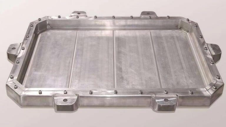
Case Study: CFRP Wing Part Milling
Consider the machining of Carbon Fiber Reinforced Polymer (CFRP) wing components requiring a precise surface finish (e.g., Ra 1.2μm). In one comparative study using dry cutting, switching from a specialized carbide end mill to a PCD milling cutter yielded dramatic improvements. Despite using significantly higher parameters with PCD, the tool achieved a lifespan five times longer than the carbide alternative. This clearly demonstrated PCD’s superior wear resistance translating into substantially higher machining efficiency and improved surface quality under demanding conditions.
The specific parameters compared in this case were:
| Material | ZY PCD milling cutter | Carbide milling tool |
|---|---|---|
| Specification (Dia.) | Φ 10 mm | Φ 10 mm |
| Vc (m/min) | 471 | 260 |
| f (mm/rev) | 0.1 | 0.07 |
| Ap (mm) | 2–5 | 2–5 |
These parameters demonstrate the performance achieved with the ZY PCD milling cutter in this specific application. Optimal settings can vary based on factors like the specific composite layup, machine rigidity, and desired outcome.

Thermal Management Advantages of PCD in Heat-Sensitive Composites
Cutting generates heat – it’s a basic principle of physics due to friction and material deformation. When machining metals, this heat can often be managed effectively. However, composite materials, especially the polymer resin matrix holding the fibers together, are often quite sensitive to heat. Excessive temperatures at the cutting edge can cause several problems:
- Melting or softening of the resin.
- Charring or burning of the resin and fibers.
- Changes in the material’s properties near the cut surface.
- Increased tool wear.
This is known as thermal damage, and it can severely compromise the integrity and performance of a finished aerospace part.
Here’s another area where PCD shines. Diamond possesses exceptionally high thermal conductivity. Think of it like a very efficient pipeline for heat. Compared to tungsten carbide, diamond can transfer heat away from the cutting zone much more rapidly. When a PCD tool cuts through a composite, the heat generated at the very tip of the cutting edge is quickly conducted away from the sensitive workpiece material, moving into the body of the tool and then potentially into the machine tool spindle.
By efficiently removing heat from the cutting interface, PCD tools help keep the temperature of the composite material below its critical damage threshold. This prevents melting, charring, and other forms of thermal degradation. Consequently, using PCD contributes significantly to maintaining the dimensional accuracy and, crucially, the structural integrity of the machined aerospace component, ensuring it meets the demanding safety and performance requirements of the industry.

What Specific Types of PCD Tooling Excel in Aerospace Machining?
Okay, so PCD is great, but what specific kinds of PCD tools actually get the job done in aerospace machining?
Aerospace relies heavily on specialized PCD tooling, including drills designed to prevent composite damage like delamination, routers and end mills for precise trimming and milling, and tailored solutions like reamers and countersinks for finishing holes. The success of these tools often hinges on specific geometric features optimized for composite materials.
PCD Drills Engineered to Minimize Delamination and Fiber Pull-out
Drilling holes in aerospace composites, especially Carbon Fiber Reinforced Polymers (CFRP), presents unique challenges. Unlike metals, composites are layered materials. If you use a standard drill bit, the pressure as the drill exits the bottom layer can easily cause the layers to split apart or “delaminate4.” Think of drilling a hole in plywood without a backer board – the wood splinters badly on the exit side. Similarly, fibers can be pulled out rather than cut cleanly. Delamination or fiber pull-out can significantly weaken the part, which is unacceptable in aerospace structures where every component’s integrity is critical.
Therefore, PCD drills designed for composites5 feature highly specialized geometries:
- Special Point Designs: Instead of a simple pointed tip like on a metal drill, PCD composite drills often use multi-facet point geometries. Common styles include “dagger” points, “brad points” with a central locating spur, or eight-facet points. These designs aim to shear the fibers cleanly at the circumference of the hole before the main cutting edges engage the center, reducing the outward pressure that causes delamination.
- Optimized Flutes: The grooves running up the drill body (flutes) are designed not just for chip removal but also for stability. For drilling stacks of different materials (like CFRP layered with aluminum or titanium, common in aerospace assemblies), specific flute shapes help manage chips from each material effectively. Some designs use straight flutes, while others employ specific helix angles tailored to reduce cutting forces.
The use of PCD ensures the sharp, intricate geometries of these special drills last much longer when cutting abrasive composites, maintaining hole quality over thousands of holes often required in structures like wing boxes or fuselage panels.
PCD Routers and End Mills for High-Speed Edge Trimming and Milling
Once composite parts are formed (often in large, near-final shapes), they usually need precise trimming around the edges or milling of features like slots and pockets. PCD routers and end mills are the tools of choice for these high-speed operations on abrasive CFRP. Using the wrong tool or a worn tool here can lead to frayed edges, delamination near the edge, or thermal damage.
Key types of PCD routers and end mills for aerospace include:
- Compression Routers: These are ingeniously designed tools, often featuring opposing helix angles on their cutting edges. Imagine special scissors that cut cleanly towards the middle from both the top and bottom surfaces simultaneously. This design pushes the top layers down and the bottom layers up during cutting, effectively “compressing” the material. This action prevents fraying or chipping on both the entry and exit surfaces, crucial for achieving clean, sharp edges on parts like composite fairings or access panels.
- Diamond-Segmented or Brazed PCD Routers: For heavy-duty edge trimming or machining thicker composite structures, routers with large, brazed PCD segments or specific diamond patterns provide maximum durability and tool life. Some designs incorporate chip-breaker geometries to help manage the dust-like chips produced when cutting composites.
- PCD End Mills: Used for creating pockets, slots, or performing profile milling. Like drills, their geometry (rake angles, clearance angles, helix angles) is optimized for shearing composite fibers cleanly rather than tearing them. Consider options like PCD Ball End Mill Cutters6 for complex surfacing.
The high wear resistance of PCD allows these tools to maintain their cutting performance at high speeds, enabling efficient material removal while ensuring the required edge quality and dimensional accuracy for aerodynamic surfaces and structural components.
Specialized PCD Solutions: Reamers, Countersinks, and Combination Tools
Beyond basic drilling and milling, aerospace manufacturing often requires highly precise finishing operations for holes where fasteners (like rivets or bolts) will be installed.
- PCD Reamers: After a hole is drilled, a reamer might be used to bring the hole to its final, highly accurate diameter and improve its surface finish. PCD reamers7 ensure excellent size control and surface quality, maintaining these standards over many parts due to PCD’s wear resistance.
- PCD Countersinks: Many aerospace fasteners require a conical or angled opening (a countersink) at the top of the hole so the fastener head sits flush with the surface. PCD countersinks create clean, precise angled features without damaging the surrounding composite material.
For tools like these, particularly those requiring both extreme hardness at the cutting edge and overall tool body strength, a common manufacturing approach becomes highly relevant:
Manufacturers often weld or braze a PCD cutting head or tip onto a body made of cemented carbide. This construction cleverly combines the advantages of both materials: the extreme hardness and wear resistance of the PCD cutting edge handle the demanding composite material, while the tougher, more rigid carbide body provides robust support and stability for the tool. This approach is highly suitable for producing tools like PCD countersink drills. Compared to traditional solid carbide countersinks, these PCD-tipped tools generally produce a better surface finish in the countersunk area and offer significantly extended processing life, making them highly cost-effective for the thousands of fastener holes found on aircraft structures.
- Combination Tools: To improve efficiency, especially in automated robotic systems common in aerospace assembly, combination tools are often used. For example, a single tool might drill the initial hole and then create the countersink in one pass (drill-countersink). Using PCD for the cutting edges of these complex tools ensures longevity and consistent performance.
Key Geometric Features Tailored for Composite Cutting
While specific tool types have unique designs, several key geometric principles apply across most PCD tools intended for aerospace composites:
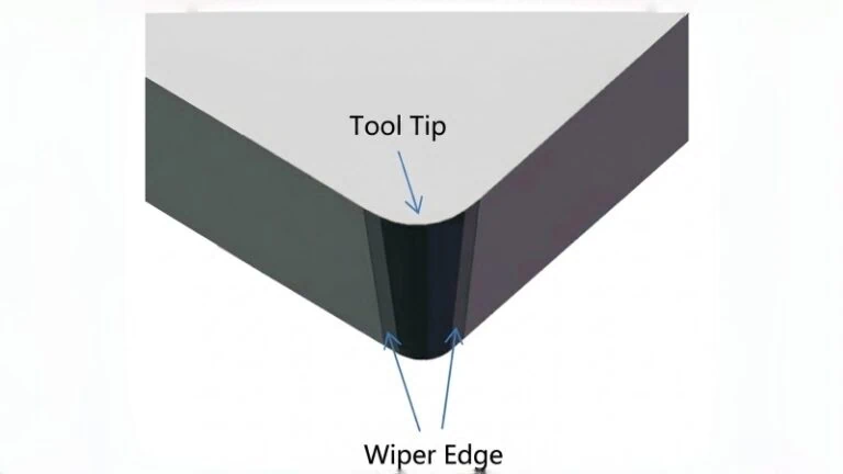
- Sharp Cutting Edges: Unlike some metal machining where a slightly rounded edge can add strength, composite machining generally demands the sharpest possible cutting edges to shear fibers cleanly rather than push or tear them. PCD can be honed to extremely sharp, durable edges.
- Rake Angles: The angle of the cutting face relative to the workpiece is critical. For composites, low positive or even negative rake angles are often employed to provide a strong cutting edge and control chip formation, minimizing lifting forces that can cause delamination.
- Clearance Angles: Sufficient clearance behind the cutting edge is needed to prevent rubbing against the machined surface, which can generate heat and friction. However, too much clearance can weaken the edge. Finding the right balance is key.
- Helix Angles (for drills/end mills): The angle of the flutes affects chip evacuation and cutting forces. Low helix angles or specialized variable helix designs are often preferred for composites to control forces and prevent delamination, especially in stacked materials.
It is crucial to understand that the “perfect” geometry isn’t universal. The optimal rake angle, helix angle, or point geometry can vary significantly based on the specific type of composite (e.g., CFRP vs. Glass Fiber, woven fabric vs. unidirectional tape), the resin system used, and the specific machining operation. Therefore, relying on generalized parameters is often insufficient. Always consult the tool supplier’s recommendations, like those provided by ZY for their specific PCD tool offerings, as they engineer these geometries based on extensive testing for particular aerospace materials and applications.

How Can You Maximize Performance and Tool Life with PCD?
So you’ve chosen the right PCD tool, but how do you actually use it to get the best performance and make it last as long as possible?
Maximizing PCD tool performance and life in aerospace composite machining involves carefully establishing optimal cutting parameters (speeds, feeds), ensuring exceptional machine tool rigidity and secure workpiece fixturing, implementing effective strategies for chip/dust management and cooling, and proactively identifying signs of tool wear to prevent catastrophic failure.
Establishing Optimal Cutting Parameters (Speeds, Feeds, Depth of Cut)
Using the right recipe of speeds and feeds is fundamental to getting the most out of your PCD tooling. Key parameters include:
- Cutting Speed (Vc): Measured in meters per minute (m/min) or surface feet per minute (SFM), this is how fast the cutting edge moves across the material surface. PCD’s hardness and thermal conductivity often allow for significantly higher cutting speeds compared to carbide when machining composites, leading to faster cycle times.
- Feed Rate (f): This is how fast the tool advances into the material, often measured per revolution (mm/rev or inch/rev) or per tooth (mm/tooth or inch/tooth). Finding the right feed rate is crucial – too low is inefficient, while too high can increase cutting forces, potentially causing chipping on the brittle PCD edge or delamination in the composite.
- Depth of Cut (ap) / Width of Cut (ae): These define how much material is removed in each pass. While PCD is wear-resistant, taking excessively large cuts can overload the tool.
Finding the “sweet spot” involves balancing these factors. Higher speeds can boost productivity, but they must be matched with appropriate feed rates and depths of cut that the tool geometry and machine setup can handle without causing excessive wear, heat buildup, or tool breakage.
Where do you start? Tool suppliers, like ZY, typically provide recommended starting parameters for their tools based on specific materials and applications. For example, the case study mentioned earlier achieved excellent results milling CFRP with a ZY PCD tool at Vc = 471 m/min and f = 0.1 mm/rev. However, it’s vital to remember that these are often starting points. Optimal parameters are highly dependent on the specific composite material (fiber type, resin, layup), the rigidity of your machine tool and workpiece setup, and the desired surface finish. Always use supplier recommendations as a starting point and be prepared to adjust parameters based on observing the actual cutting performance, chip formation, surface quality, and tool wear in your specific environment.
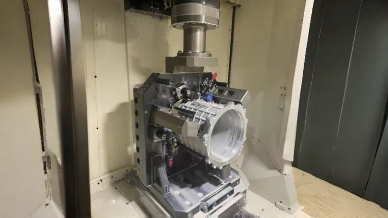
The Critical Role of Machine Tool Stability and Workpiece Fixturing
Imagine trying to write neatly on a shaky table – it’s nearly impossible, right? Machining composites with PCD tools requires an extremely stable environment for similar reasons.
- Machine Tool Rigidity: PCD is incredibly hard, but it’s also more brittle than carbide. Any excessive vibration coming from the machine tool (due to lack of stiffness in the frame, spindle bearings, or axes) can cause micro-impacts on the delicate PCD cutting edge, leading to premature chipping or even fracture. Therefore, using rigid, well-maintained, high-quality CNC machining centers is essential for successful PCD tooling application.
- Workpiece Fixturing: Aerospace composite parts are often large, relatively thin, and less stiff than metal components. They can easily vibrate or flex during machining if not held securely. This vibration not only harms the tool but also leads to poor surface finish and inaccurate dimensions. Secure fixturing is non-negotiable. This often involves using:
- Vacuum chucks: To hold large, flat panels securely from underneath.
- Specialized clamps: Positioned close to the cutting area to minimize unsupported sections.
- Custom fixtures: Designed to support the specific geometry of the aerospace part.
Ensuring both the machine and the workpiece are as rigid and vibration-free as possible protects the PCD tool edge, allows for consistent cutting action, and helps achieve the tight tolerances and high surface quality required in aerospace.
Effective Chip Management and Cooling/Lubrication Strategies
Machining composites doesn’t produce long, flowing chips like metals often do. Instead, it typically generates fine, abrasive dust (especially with CFRP) or small, sharp particles. Managing this effectively is crucial for several reasons:
- Health and Safety: Composite dust, particularly carbon fiber dust, can be harmful if inhaled. Powerful dust extraction systems (industrial vacuums) connected directly to the cutting area are essential to capture dust at the source.
- Surface Finish: Allowing dust and particles to accumulate can lead to them being re-cut or pressed into the machined surface, degrading the finish quality.
- Tool Life: Packed dust in the tool’s flutes can increase friction and heat, accelerating wear.
Cooling and Lubrication:
- Dry Machining: For many CFRP applications, dry machining (cutting without liquid coolant/lubricant) is often preferred. This avoids potential contamination of the composite material by cutting fluids, which can sometimes interfere with later bonding or painting processes. In these cases, heat management relies on PCD’s high thermal conductivity (drawing heat away) and often uses a directed air blast to help clear chips and provide some convective cooling.
- Minimum Quantity Lubrication (MQL): For some applications, especially machining stacks of composite and metal (like CFRP/Aluminum), a very small amount of specialized lubricant misted with compressed air (MQL) might be used. This provides lubrication mainly for the metallic layer while minimizing composite contamination.
- Flood Coolant: Generally avoided for purely composite machining but may be necessary if significant amounts of metal are being cut simultaneously within a stackup.
The primary goals are always to effectively remove the abrasive dust/chips away from the cutting zone and to manage heat without compromising the composite material’s integrity.
Identifying and Preventing Premature Tool Wear or Chipping
While PCD tools offer exceptional life, they don’t last forever and can be susceptible to chipping if not used correctly. Maximizing value means monitoring wear and replacing the tool before it fails catastrophically, which could damage an expensive aerospace part.
- Understanding Wear Modes:
- Gradual Flank Wear: This is the preferred, predictable wear mode where the edge slowly wears down over time.
- Chipping: Small pieces breaking off the cutting edge, often due to impact, vibration, or excessive cutting forces. This is undesirable as it degrades surface finish and can lead to rapid total failure.
- Fracture: Complete breakage of the PCD tip, usually due to a major impact, excessive force, or a pre-existing defect.
- Monitoring Strategies:
- Visual Inspection: Regularly inspecting the cutting edge under magnification can reveal early signs of wear or minor chipping.
- Surface Finish Monitoring: A noticeable decline in the quality of the machined surface is often an indicator that the tool edge is degrading.
- Cutting Force / Spindle Load Monitoring: Modern CNC machines can monitor the power required to cut. A gradual or sudden increase can indicate the tool is becoming dull or damaged.
- Tool Life Tracking: Based on experience or supplier recommendations, track how many parts or how much distance a tool has cut and plan replacements proactively.
- Prevention: How do you avoid premature failure?
- Use Correct Parameters: Avoid overly aggressive feeds or depths of cut (refer to H3.1).
- Ensure Stability: Minimize vibration through rigid machines and secure fixturing (refer to H3.2).
- Proper Handling: PCD tools should be handled carefully to avoid dropping or bumping the delicate cutting edges.
- Smooth Entry/Exit: Program tool paths to enter and exit the material smoothly where possible, avoiding sudden impacts.
By carefully applying the right parameters, ensuring a stable cutting environment, managing chips effectively, and monitoring tool condition, you can consistently achieve the long life and high performance potential of PCD tooling in demanding aerospace composite applications.
Conclusion
In conclusion, Polycrystalline Diamond (PCD) tooling represents a significant advancement for machining the abrasive and challenging composite materials prevalent in the modern aerospace industry. Its inherent properties – exceptional hardness, outstanding wear resistance, and high thermal conductivity – directly address the primary difficulties encountered when cutting materials like CFRP, leading to longer tool life, improved process consistency, tighter tolerances, and superior surface finishes compared to traditional carbide or coated tools.
Successfully leveraging PCD, however, goes beyond simply choosing the material. Specialized tool designs, including uniquely engineered drills, compression routers, and precise finishing tools like reamers and countersinks, are crucial for tackling specific tasks like preventing delamination or achieving perfect edge quality. Furthermore, the geometry of these tools is finely tuned for composite interaction.
Ultimately, unlocking the full potential of PCD requires a holistic approach. Establishing the correct cutting parameters, ensuring a highly stable machining environment through machine rigidity and robust workpiece fixturing, managing abrasive dust effectively, and implementing proactive tool wear monitoring are all essential practices. While PCD tools may represent a higher initial investment, their extended lifespan, ability to maintain quality over long production runs, and potential for increased machining efficiency often translate into superior overall value and reliability for critical aerospace component manufacturing.
Ready to find the optimal PCD tooling solution for your specific aerospace composite application? Submit your inquiry now for expert recommendations and a personalized quote.
References
- Sintering1 – ScienceDirect topic page explaining the sintering process used in creating materials like PCD.
- Tight Tolerances2 – GD&T Basics resource explaining Geometric Dimensioning and Tolerancing symbols and concepts related to manufacturing precision.
- Difference between PCD and carbide tools3 – ZYDiamondTools blog post detailing the comparison between PCD and Carbide cutting tools.
- Delaminate4 – ScienceDirect topic page explaining delamination as a failure mode in layered materials like composites.
- PCD drills designed for composites5 – ZYDiamondTools product page for a PCD countersink drill suitable for composite materials.
- PCD Ball End Mill Cutters6 – ZYDiamondTools product page for PCD ball end mills.
- PCD reamers7 – ZYDiamondTools product page for custom PCD forming reamers.