-
Whatsapp: +86 13526572721
-
Email: info@zydiamondtools.com
-
Address: AUX Industrial Park, Zhengzhou City, Henan Province, China
-
Whatsapp: +86 13526572721
-
Email: info@zydiamondtools.com
-
Address: AUX Industrial Park, Zhengzhou City, Henan Province, China

Machining Advanced Technical Ceramics: Efficient Grinding and PCD Milling Strategies for Alumina and Zirconia
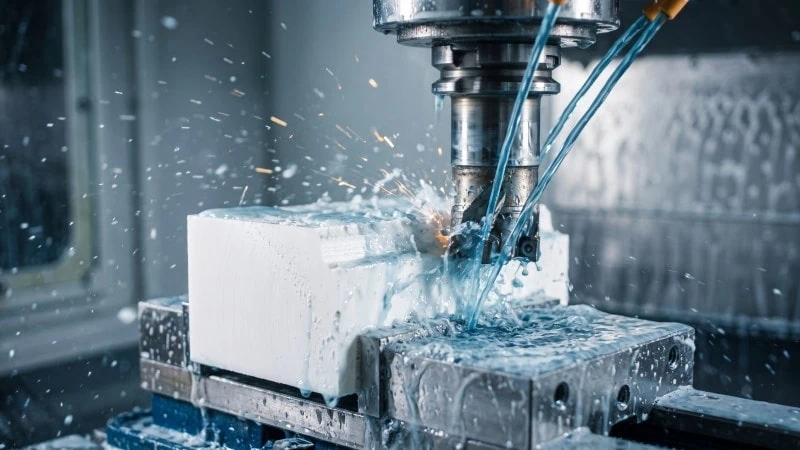
How can manufacturers efficiently machine advanced technical ceramics like alumina1 and zirconia2 without causing catastrophic fractures or excessive tool wear?
Manufacturers achieve efficient ceramic machining by implementing a strict two-phase workflow: utilizing Polycrystalline Diamond (PCD) milling exclusively for pre-sintered (green) high-volume material removal, and relying solely on precision diamond grinding for post-sintered finishing. By strictly controlling spindle speeds, utilizing advanced coolant delivery systems during grinding, and adapting abrasive tool geometries to specific material properties, operators can minimize thermal shock, maximize tool life, and prevent hidden subsurface damage.
Green vs. Sintered State Machining: Defining the Workflow
When processing advanced ceramics, should you remove the bulk of the material before or after the firing process?
The optimal workflow dictates machining in two distinct phases. First, use pre-sintered (green) machining to remove up to 95% of the bulk material. Second, utilize post-sintered (hard) machining to achieve tight final tolerances and smooth surface finishes. This phased approach minimizes tool wear and prevents catastrophic part fractures.
Pre-sintered Machining for High-Volume Material Removal
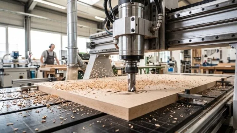
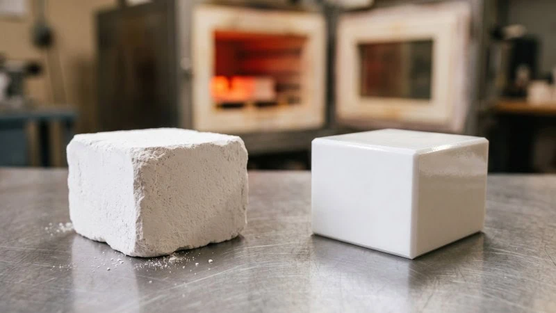
Advanced technical ceramics begin as a pressed powder mixed with binding agents. In this initial “green” state, the material is quite soft. It handles very similarly to compacted powdered metal before sintering. Therefore, pre-sintered machining focuses entirely on removing material quickly using traditional cutting kinematics, such as milling and turning.
Why is green machining so crucial? Fully fired ceramics are incredibly hard and brittle. Machining them takes immense time and energy. By roughing out the shape first, you save significant machine time. Think of it like roughing out a soft tool steel blank before sending it to the heat-treatment furnace. You cut the part as close to the final net shape as possible while it is still soft.
During this stage, cutting forces remain very low. Spindle speeds can run high, and material flies off the block easily. Manufacturers routinely remove 90% to 95% of the total excess volume here.
However, you cannot machine the green part to its exact final dimensions. During the kiln firing process, the ceramic part will naturally shrink. This volume shrinkage rate is typically between 15% and 25%. Because exact shrinkage parameters vary based on specific powder mixtures and curing profiles, you must always verify the exact shrinkage rate with your material supplier before finalizing your CNC toolpaths. You must scale your initial 3D models up to perfectly accommodate this anticipated shrinkage.
Hard Machining for Final Tolerances and Surface Finish
After the part cures in a kiln, it enters the fully sintered state. The material is now fully dense. It possesses the extreme hardness that advanced ceramics are famous for. Consequently, you can no longer use standard milling techniques or fixed-edge cutting tools to remove material. Applying a traditional end mill to sintered alumina will cause the cutting edge to shatter instantly, ruining the part and creating a severe safety hazard.
Instead, hard machining strictly utilizes abrasive diamond grinding to focus on precision and surface integrity. You typically only remove the remaining 5% of material. This phase corrects any physical warping that occurred during the high-temperature firing process. Furthermore, it ensures the final part hits strict dimensional tolerances. Some medical or aerospace applications require dimensional tolerances as tight as ±0.002 mm.
To achieve this, machinists rely on highly specialized, slow-feed grinding processes. This is highly comparable to the delicate process of precision hard-turning a fully hardened D2 steel die, but using abrasive wheels instead of inserts. You must take extremely light, controlled passes. Applying high mechanical forces here will easily fracture or chip the brittle ceramic part.
| Process Phase | Material State | Primary Objective | Typical Material Removed | Machining Method |
|---|---|---|---|---|
| Pre-sintered (Green) | Soft, pressed powder | High-volume removal | 90% – 95% | PCD Milling / Turning |
| Post-sintered (Hard) | Fully dense, hard | Tolerances and finish | 5% – 10% | Diamond Grinding |
Ultimately, patience and absolute machine stability are vital during this final phase. You are no longer roughing out a shape; you are gently coaxing the ceramic into its perfect final form.
Maximizing Efficiency with PCD Milling Tools in the Green State
How can manufacturers effectively mill pre-sintered ceramics without the highly abrasive raw powders instantly destroying their cutting tools?
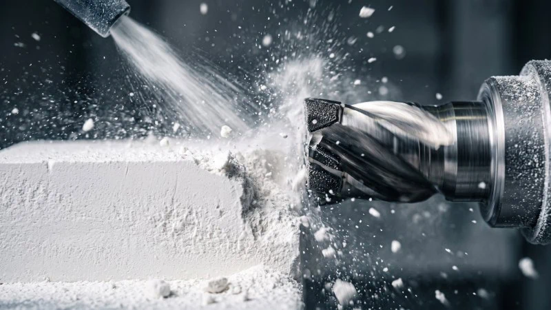
Manufacturers maximize green machining efficiency by utilizing Polycrystalline Diamond (PCD) milling tools3, which offer unparalleled abrasion resistance compared to standard tungsten carbide4. By optimizing spindle speeds, carefully managing dust extraction or compatible coolants, and controlling feed rates to eliminate chatter, machinists can maintain razor-sharp edges and tight tolerances during the pre-sintered milling phase.
The Mechanical Advantages of Polycrystalline Diamond
Even in the soft green state, technical ceramics like alumina and zirconia are composed of highly abrasive microscopic particles. Standard carbide tools simply cannot handle this constant abrasion. Using carbide on green ceramics is like using a standard steel drill bit to cut through thick fiberglass—the abrasive particles rapidly sand away the cutting edge.
Therefore, Polycrystalline Diamond (PCD) becomes the superior choice for green machining. PCD is manufactured by sintering microscopic diamond particles together under extreme high pressure and high temperature. Consequently, it creates an incredibly dense and wear-resistant cutting matrix.
- Extreme Hardness: PCD boasts a Vickers hardness5 of approximately 50 to 80 GPa. In contrast, standard tungsten carbide only reaches about 15 to 20 GPa.
- Superior Wear Resistance: The synthetic diamond structure strongly resists the sandpaper-like abrasion of green ceramic powders. This directly translates to longer, more predictable tool life.
- Sharp Cutting Edges: PCD can maintain a razor-sharp cutting edge for extended periods, cleanly shearing the binder and powder matrix without crumbling the fragile green edges.
As a result, PCD tools reduce the frequency of tool changes. This directly lowers machine downtime and boosts overall production efficiency before the parts even reach the kiln.
Optimizing Spindle Speeds and Feed Rates to Reduce Chatter
To get the most out of PCD tools in the green state, you must dial in the correct cutting parameters. Incorrect settings quickly lead to “chatter.” Chatter is a severe harmonic vibration between the tool and the workpiece, which can easily fracture the delicate pre-sintered material and shatter the brittle PCD cutting edges.
To eliminate chatter, operators must balance high spindle speeds with carefully calculated feed rates. High spindle speeds (RPM) allow the PCD tool to cleanly evacuate the powdered material. However, the feed rate must be low enough to prevent excessive mechanical stress on the fragile green block, but high enough to prevent the tool from simply rubbing.
| Tool Diameter (mm) | Spindle Speed (RPM) | Feed Rate (mm/min) | Max Depth of Cut (mm) |
|---|---|---|---|
| 2.0 | 18,000 – 24,000 | 150 – 250 | 0.50 |
| 4.0 | 14,000 – 18,000 | 250 – 350 | 1.00 |
| 6.0 | 10,000 – 15,000 | 300 – 450 | 1.50 |
Note: Optimal cutting parameters vary based on specific PCD diamond grain sizes, binder materials, and machine rigidity. Always verify baseline RPM and feed rate ranges with your tool manufacturer’s documentation before running a production job.
Tool Wear Management and Thermal Control
Even the toughest PCD tools eventually wear down. The primary enemies of PCD longevity are excessive heat and abrasion.
When milling green ceramics, the friction generates localized heat at the cutting zone. If this heat builds up, it degrades the binder material holding the diamond particles together. Because many green ceramic binders are sensitive to water, flood coolant cannot always be used (as it may dissolve the part). Instead, operators frequently rely on high-velocity air blasts and specialized vacuum dust extraction systems. This removes the abrasive chips and cools the tool simultaneously.
“Consistent thermal management and immediate evacuation of abrasive dust are the primary defenses against premature PCD tool failure.”
To manage wear effectively:
- Optimal Evacuation: Ensure a steady, high-pressure air blast clears powdered chips away from the cutting zone immediately so the tool doesn’t re-cut abrasive dust.
- Avoid Thermal Shock: If utilizing liquid coolants (on compatible binder systems), never start a cut dry and then turn the coolant on mid-cut. The sudden temperature drop will instantly crack the PCD insert.
- Monitor Flank Wear: Regularly inspect the tool under magnification. Swap out the tool when flank wear reaches the manufacturer’s recommended limit to prevent catastrophic tool failure.
Precision Diamond Grinding Techniques for Sintered Ceramics
When finishing fully sintered ceramics, how can you consistently achieve ultra-tight tolerances without fracturing the brittle workpiece?
To achieve ultra-tight tolerances safely on fully fired ceramics, operators must abandon fixed-edge tools and use precision diamond grinding wheels tailored with the exact grit size and bond type. By pairing these specialized abrasive wheels with high-pressure, precisely targeted coolant delivery systems, machinists can effectively manage intense thermal loads, prevent destructive micro-cracking, and guarantee pristine final surface integrity.
Selecting the Optimal Wheel Grit and Bond Type
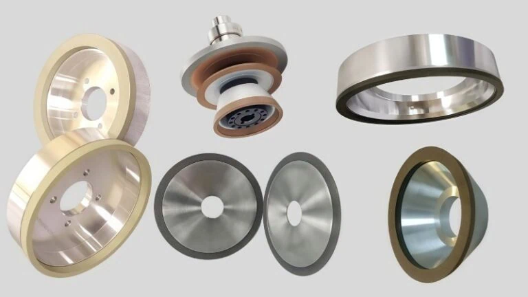
Grinding fully sintered technical ceramics requires specific diamond wheels. You cannot use a standard aluminum oxide wheel meant for mild steel. The extreme hardness of fired ceramics will instantly dull a standard wheel. Instead, you must carefully select the right diamond grit size and the material that holds those diamonds together, known as the bond6.
Choosing the right grit size determines your material removal rate and final finish. For initial bulk removal during the grinding phase, operators typically use a coarser grit, such as D107 or D126. These larger diamonds aggressively sheer away material. However, they leave deep scratch marks. Therefore, you must switch to a finer grit, like D46 or D15, for the final finishing passes. This process is very similar to progressively stepping down abrasive grits when polishing a hardened plastic injection mold base.
The bond type is equally important. The bond holds the diamond particles in place. As the diamonds dull, the bond must slowly wear away to expose fresh, sharp diamonds beneath.
| Bond Type | Hardness | Primary Advantage | Best Application |
|---|---|---|---|
| Resin Bond | Softest | Fast cutting, excellent finish | Fine finishing passes |
| Metal Bond | Hardest | Long wheel life, holds shape | Heavy stock removal |
| Vitrified Bond | Medium | Highly porous for cool cutting | High-precision profiling |
Advanced Coolant Delivery Systems to Prevent Micro-cracking
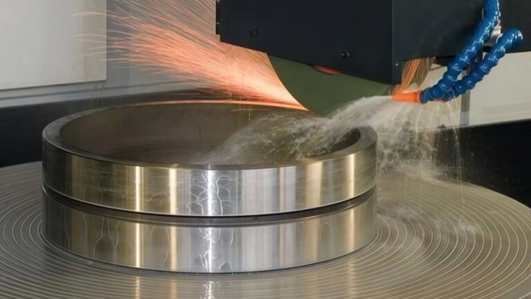
Diamond grinding creates severe friction. This friction generates immense heat directly at the point of contact. If this heat transfers into the ceramic workpiece, the material expands rapidly. Because sintered ceramics are extremely brittle, this sudden localized expansion causes micro-cracking.
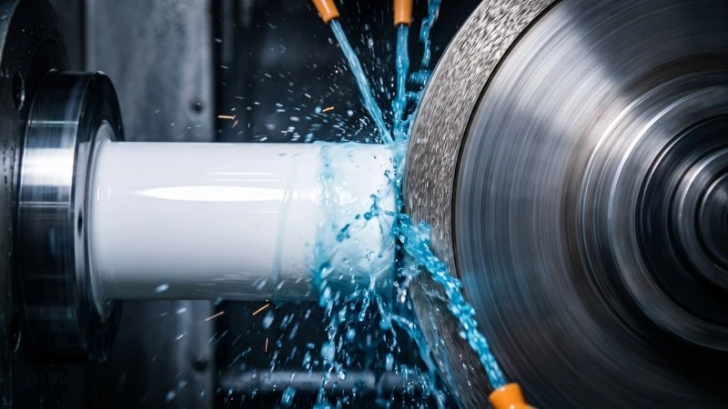
Therefore, keeping the grinding zone cool is mandatory. Simply trickling coolant onto the wheel is never enough. The high-speed rotation of the grinding wheel creates an invisible barrier of air. This air barrier easily deflects low-pressure coolant away from the actual cut.
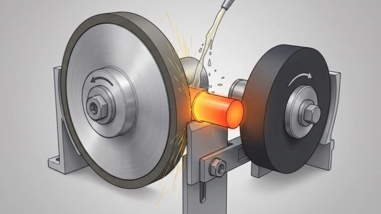
To break through this air barrier, you must use high-pressure coolant delivery systems. You must aim high-pressure nozzles directly into the nip point where the wheel meets the ceramic part. This technique is exactly like using high-pressure through-spindle coolant to clear chips and heat during a deep-hole drilling operation on stainless steel.
Furthermore, water-soluble synthetic coolants are generally preferred. They offer superior heat dissipation compared to straight cutting oils. Consistent, high-volume cooling prevents thermal shock7 and keeps the ceramic structure completely intact.
Strategies for Controlling Surface Integrity
Surface integrity refers to the overall health of the machined surface. A part may look shiny, but it could hide severe structural damage just below the surface. Controlling this integrity requires strict discipline over your machine settings.
“A flawless surface finish is the direct result of controlled feeds, shallow depths of cut, and rigorous wheel dressing.”
First, you must keep your depth of cut (DOC) incredibly shallow during final passes. Often, operators limit the DOC to just 0.005 mm per pass. Taking deeper cuts increases mechanical stress and pushes micro-cracks deeper into the part.
Second, utilize frequent “spark-out” passes. A spark-out pass involves running the grinding wheel over the part without feeding it any deeper. This allows the wheel to gently relieve any built-up mechanical pressure. It effectively sparks out the remaining microscopic high spots.
Finally, maintain the grinding wheel through regular truing and dressing. A glazed wheel will rub instead of cut. This rubbing generates excessive heat and destroys surface integrity. By using an aluminum oxide dressing stick8, you strip away the loaded ceramic dust and expose sharp diamonds, ensuring a clean, stress-free cut.
Material-Specific Adjustments: Alumina vs. Zirconia
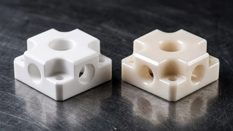
Switching between technical ceramics like alumina and zirconia requires operators to completely adapt their grinding strategies to the specific mechanical properties of the workpiece. Sintered alumina demands incredibly rigid setups and ultra-low radial engagement to combat its extreme hardness and poor thermal conductivity. Conversely, zirconia requires exceptionally sharp abrasive grains and carefully controlled feed rates to overcome its high fracture toughness and persistent machining resistance.
Overcoming the Extreme Hardness and Low Thermal Conductivity of Alumina
Alumina, or aluminum oxide, is one of the most common technical ceramics. It is highly valued for its extreme wear resistance. However, this exact characteristic makes it notoriously difficult to grind.
First, alumina is exceptionally hard. Machining high-purity sintered alumina is very similar to grinding a solid block of hardened tungsten carbide. The material constantly fights the abrasive grains. Therefore, you must use highly rigid machine tools. Any spindle runout or machine vibration will cause irregular wheel wear and poor surface finish. You must maintain incredibly light radial engagement during grinding passes. Taking a heavy step-over will overload the wheel and chip the brittle ceramic edge.
Because mechanical properties fluctuate based on purity levels (e.g., 95% versus 99.8% alumina), grinding parameters must be calibrated to the specific grade being machined.
Second, alumina has very low thermal conductivity. When you cut metals like aluminum, the heat transfers directly into the metal chips. The chips then carry the heat away from the part. Alumina grinding dust does not absorb heat in the same way. Consequently, all the grinding heat reflects directly back into your wheel and the workpiece surface.
“When grinding sintered alumina, heat is your greatest enemy because the material itself offers no thermal relief.”
To overcome this, you must rely entirely on external cooling. You cannot grind sintered alumina dry. Operators must utilize high-volume flood coolant to carry the heat away. Additionally, utilizing climb grinding strategies helps minimize the time the abrasive spends rubbing against the surface, which reduces friction and keeps operating temperatures lower.
Adapting to the High Fracture Toughness and Machining Resistance of Zirconia
Zirconia behaves very differently than alumina. It is often referred to as the “steel” of the ceramic world. While it is slightly softer than alumina, it possesses remarkably high fracture toughness9.
Fracture toughness measures a material’s ability to resist cracking under stress. Because zirconia absorbs energy without fracturing as easily, it exhibits severe machining resistance. It actively pushes back against the grinding wheel. This behavior closely mirrors the process of abrasive machining on work-hardening superalloys. The material yields slightly before the abrasive grain finally shears it away.
| Material Property | Alumina (99.5%) | Zirconia (Y-TZP) | Grinding Impact |
|---|---|---|---|
| Vickers Hardness | ~15 – 19 GPa | ~12 – 13 GPa | Alumina wears diamond wheels significantly faster. |
| Fracture Toughness | ~4 – 5 MPa·m½ | ~8 – 10 MPa·m½ | Zirconia resists grinding forces strongly, requiring sharper abrasives. |
| Thermal Conductivity | ~30 W/m·K | ~2 – 3 W/m·K | Both require intense high-pressure external cooling. |
To effectively adapt to zirconia, you must maintain a highly open and sharp wheel condition. A dull or loaded grinding wheel will simply rub against the zirconia. This rubbing action generates massive pressure and heat, which can warp the final part or cause phase transformation on the surface.
Furthermore, you must maintain a constant, steady feed. You cannot allow the wheel to dwell or pause in the cut. If the wheel dwells, it creates severe localized stress. This stress can trigger a monoclinic phase transformation in the zirconia structure, weakening the final component. Keep the wheel moving steadily to cleanly grind the tough material away.
Troubleshooting Common Ceramic Machining Defects
Resolving common ceramic machining defects requires adjusting toolpaths to prevent exit chipping and controlling cut depths to stop subsurface micro-cracking. By using sacrificial support plates and implementing strict spark-out passes, machinists can preserve structural integrity and guarantee a flawless final yield.
Preventing Edge Chipping During Exit Cuts
Edge chipping happens mostly when a cutting tool or grinding wheel leaves the ceramic workpiece. Because technical ceramics are incredibly brittle, they lack the flexibility to bend away from the machining force. Instead, the very edge simply snaps off. This problem closely mirrors what happens when you drill a deep through-hole into a brittle cast iron block. The drill bit often blows out the back wall as it forcefully exits the cut.
To stop edge chipping, you must provide mechanical support to the exit area or reduce the cutting pressure.
Practical Toolpath and Setup Solutions
You can easily modify your machining setup to fix this issue. Here are the most effective methods to protect fragile edges during both green milling and hard grinding:
| Strategy | Implementation Method | Why It Works |
|---|---|---|
| Sacrificial Backing | Clamp a compatible backing block directly against the exit face. | The tool or wheel cuts smoothly into the backing, keeping the ceramic edge fully supported. |
| Pre-Chamfering | Create a small 45-degree chamfer on the exit edge before the main pass. | It removes the sharp, fragile corner entirely before heavy machining forces hit it. |
| Feed Rate Reduction | Program the CNC to slow down the feed rate by 50% right before the exit. | It dramatically lowers the mechanical pressure exactly when the edge is most vulnerable. |
Additionally, always ensure your toolpaths use climb cutting or climb grinding. This pushes the machining forces into the solid bulk of the material, preventing the tool from pushing outward toward the fragile unsupported edge.
Identifying and Eliminating Subsurface Damage
Subsurface damage is a hidden threat in sintered ceramics. Your ceramic part might look perfectly shiny and flawless on the outside. However, tiny micro-cracks can easily hide just below the surface. If left unchecked, these hidden cracks will eventually cause the part to shatter under operational stress. This is very similar to a hidden stress fracture inside a hardened steel stamping die. The die looks fine until it suddenly splits in half during a heavy stamping press cycle.
Detecting Hidden Cracks
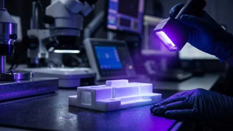
How do you find cracks you cannot see? You cannot rely on a simple visual check. Instead, quality inspectors use fluorescent dye penetrant testing10. They soak the ceramic part in a special liquid dye. The dye seeps down into any microscopic surface cracks. Next, they wash the part and inspect it under an ultraviolet (UV) light. The trapped dye glows brightly, clearly revealing the hidden damage network. Acceptable limits for subsurface damage depend strictly on the aerospace or medical standards governing the final application.
Eliminating the Root Cause
Excessive mechanical pressure during the grinding phase causes subsurface damage. To eliminate it, you must reduce the physical force your abrasive pushes into the ceramic part.
“The key to eliminating subsurface damage is taking incredibly light finishing passes with a perfectly dressed, sharp wheel.”
First, drastically lower your depth of cut (DOC) on the final passes. Second, implement regular spark-out passes. A spark-out pass means running the wheel over the exact same path again without feeding it any deeper. This zero-pressure pass gently shaves off any remaining microscopic tension. Finally, always use a freshly dressed, sharp abrasive edge. A glazed wheel rubs and crushes the ceramic, instantly forcing destructive micro-cracks deep into the material structure.
Conclusion
Successfully machining advanced technical ceramics like alumina and zirconia requires a strict, two-phase approach that respects the extreme properties of the material. By leveraging the bulk-removal advantages of PCD milling exclusively during the pre-sintered green state, and utilizing tailored diamond grinding parameters for the fully sintered hard state, manufacturers can conquer the inherent brittleness of these ceramics. Whether adapting to the highly abrasive nature of alumina or overcoming the fracture toughness of zirconia, applying these physically accurate techniques will prevent catastrophic tool failure, minimize defects, and ensure superior surface integrity.
References
- Alumina1 – Wikipedia article explaining the properties and engineering applications of aluminum oxide.
- Zirconia2 – Wikipedia article covering the characteristics and structural stability of zirconium dioxide.
- Polycrystalline Diamond (PCD) milling tools3 – ZYDiamondTools guide detailing the definition and milling applications of PCD end mills.
- Standard Tungsten Carbide4 – ZYDiamondTools blog post exploring the critical differences between PCD and traditional carbide cutting tools.
- Vickers Hardness5 – Wikipedia article detailing the Vickers hardness test methods and metrics for hard materials.
- Bond6 – ZYDiamondTools article explaining how to select the right grinding wheel bond for optimal performance.
- Thermal Shock7 – Wikipedia article explaining thermal shock resistance in ceramics and brittle materials.
- Aluminum Oxide Dressing Stick8 – ZYDiamondTools product page featuring WA dressing sticks used for maintaining diamond grinding wheels.
- Fracture Toughness9 – Wikipedia article explaining fracture toughness concepts and crack propagation resistance.
- Fluorescent Dye Penetrant Testing10 – Wikipedia article covering the process and applications of dye penetrant inspection for detecting surface-breaking defects.