-
Whatsapp: +86 13526572721
-
Email: info@zydiamondtools.com
-
Address: AUX Industrial Park, Zhengzhou City, Henan Province, China
-
Whatsapp: +86 13526572721
-
Email: info@zydiamondtools.com
-
Address: AUX Industrial Park, Zhengzhou City, Henan Province, China

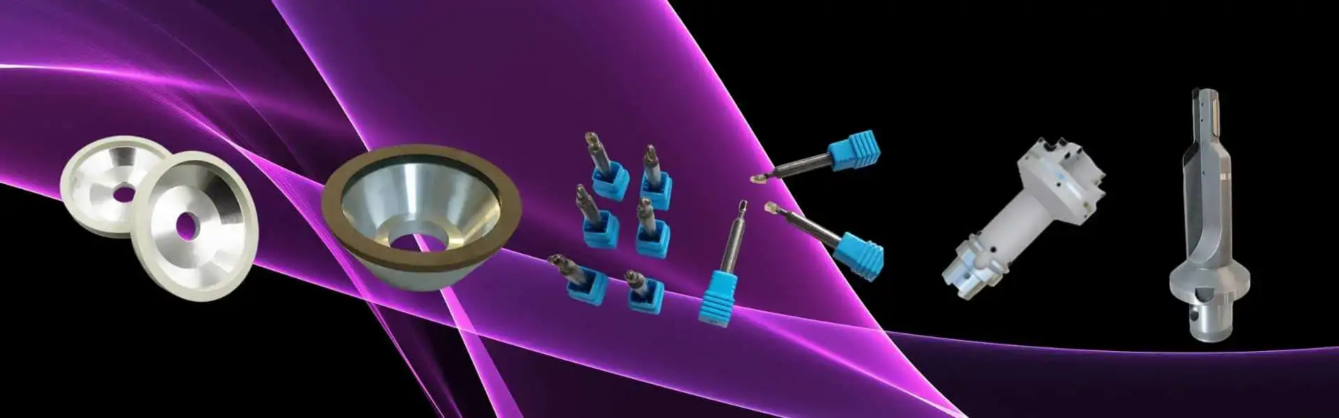
Diamond and CBN Wheel Shapes Explained: What Do 1A1, 11V9, and 12V9 Mean?

What do specific shape codes like 1A1, 11V9, and 12V9 actually mean when selecting diamond and CBN grinding wheels1 for your machine shop?
These alphanumeric codes belong to the standard FEPA classification system, which dictates the core geometry, abrasive cross-section profile, and exact abrasive location of a grinding wheel. Specifically, a 1A1 is a straight wheel used for heavy surface grinding, an 11V9 is a highly rigid flaring cup for top grinding, and a 12V9 is a swept-back dish wheel engineered to provide maximum lateral clearance when sharpening fine-pitch cutting tools.
How the FEPA Standard Coding System Works
How exactly does the FEPA coding system dictate the shape of diamond and CBN grinding wheels?
The Federation of European Producers of Abrasives (FEPA) standard coding system uses a three-part alphanumeric sequence to specify grinding wheel geometry. The first number dictates the core body shape, the middle letter identifies the abrasive cross-section profile, and the final number indicates the exact location of the abrasive layer on the core. This universal standard ensures machinists can accurately match wheel designs to specific CNC grinding operations.
First Number: Core Geometry and Basic Shape
The first number in a FEPA code represents the foundational body of the grinding wheel. Therefore, this digit tells you the basic physical shape of the central core before any diamond or CBN grit is applied. The core provides the structural support for the grinding process. For instance, think of the core geometry like the base fixture on a CNC milling center2; it dictates how the tool mounts to the spindle and how much structural rigidity is present during heavy material removal.
Different machining setups require distinct core shapes to access the workpiece without causing collisions. Consequently, manufacturers use standard numbers to categorize these base shapes universally.
| Core Number | Basic Core Shape | Primary Characteristic |
|---|---|---|
| 1 | Straight | Flat, disc-like profile with a continuous outer diameter. |
| 6 | Straight Cup | Cylinder-shaped core with a deeply recessed center. |
| 11 | Flaring Cup | Tapered sides extending outward from the central hub. |
| 12 | Dish | Shallow, bowl-like shape offering high mechanical clearance. |
While the standard number defines the general shape, the exact hub thickness, bore diameter, and core material (such as steel, aluminum, or bakelite) will influence the wheel’s weight and heat dissipation.
Letter: Abrasive Cross-Section Profile
Following the first number, the middle letter identifies the profile of the abrasive layer itself. Specifically, if you were to slice the grinding wheel in half and look at the cross-section, this letter describes the geometric shape of the cutting edge.
Why does the abrasive profile matter? It determines the exact footprint of the cut. Much like how a machinist selects a sharp, angled lathe insert for precision threading and a broad, flat insert for heavy roughing, you must choose the correct abrasive profile for your specific surface finish requirements.
| Profile Letter | Cross-Section Shape | Application Focus |
|---|---|---|
| A | Rectangular | Standard flat surface grinding3 and heavy stock removal. |
| V | Angled / Tapered | Precise access into tight corners and complex tool flutes. |
| E | Rounded | Plunge grinding specific radii and machining fillets. |
| C | Concave | Shaping convex profiles on the workpiece. |
Ultimately, this letter guarantees that the working face of the wheel matches the geometric requirements of the component you are machining.
Second Number: Location of the Abrasive Section
The final digit in the FEPA code pinpoints exactly where the abrasive band is located on the core body. Even if two wheels have the identical core shape and abrasive profile, placing the grit on a different surface completely changes how the wheel cuts.
Does the wheel need to plunge radially into the material, or will it grind axially using its side face? The second number answers this question directly.
- 1 (Periphery): The abrasive is bonded to the outer circumference. This is used for radial feed, cutting along the outside diameter.
- 2 (Side/Face): The abrasive is located on the flat side. This is used for axial feed.
- 9 (Corner/Rim): The abrasive sits on the outer rim of a cup or dish shape. This allows for complex approach angles in tool and cutter grinding.
For example, a location code of “1” signifies that the wheel acts like a standard circular saw blade cutting on its edge. Conversely, a location code of “9” indicates the cutting action happens on a protruding rim. As a result, understanding this final number is critical for programming correct feed rates and toolpaths in your CNC software.
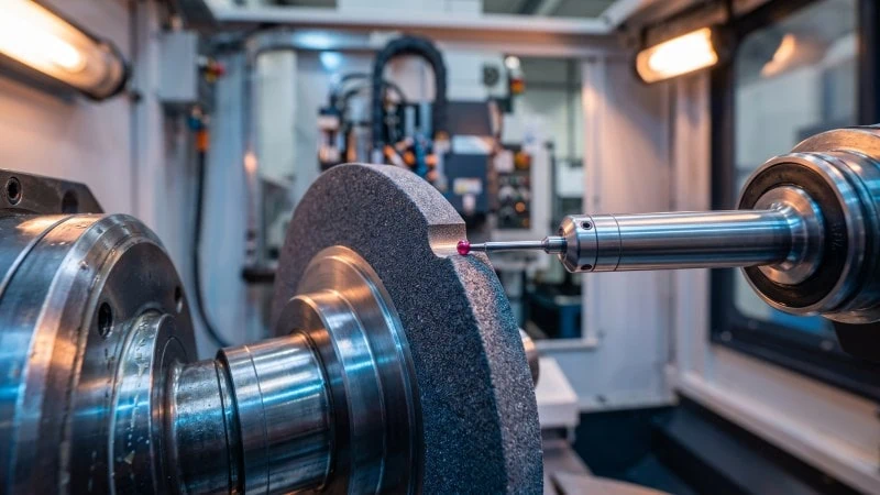
Deep Dive into the 1A1 Straight Wheel
What exactly defines a 1A1 straight wheel, and how does its geometry impact your grinding process?
The 1A1 wheel is a flat, straight grinding wheel featuring a rectangular abrasive profile located entirely on its outer periphery. This robust design provides maximum contact area between the abrasive layer and the workpiece. Consequently, it delivers exceptional stability for heavy stock removal, cylindrical grinding4, and flat surface machining.
Structural Characteristics of 1A1
Let’s break down the physical build of the 1A1 wheel. The first “1” means the core is perfectly straight. It looks like a simple, flat disc. The “A” signifies a flat, rectangular abrasive profile. Finally, the last “1” indicates the abrasive sits strictly on the outer edge.
Think of the 1A1 structure like a standard plain milling cutter5. The cutting action happens exclusively along the outside diameter. This straight geometry creates a very strong, rigid core. Therefore, it heavily resists deflection during high-pressure cuts.
The core material plays a massive role in overall performance. Manufacturers typically use steel, aluminum, or resin. Steel offers maximum rigidity. Meanwhile, aluminum reduces the overall spindle load. Resin helps absorb machining vibration.
Best Machining Applications for 1A1 Wheels
The 1A1 shape excels in high-volume production environments. Its broad, flat outer edge removes large amounts of material quickly. Machinists rely on 1A1 wheels for several heavy-duty operations.
| Grinding Operation | Primary Function | Typical Workpiece Material |
|---|---|---|
| Surface Grinding | Creating perfectly flat surfaces on block materials. | Solid Carbide, Technical Ceramics |
| Cylindrical Grinding | Reducing the outside diameter of round stock. | High-Speed Steel (HSS)6, Tungsten |
| Slotting and Fluting | Cutting deep, straight channels into solid blanks. | Carbide Blanks, Alloy Bars |
Centerless grinding7 relies heavily on 1A1 wheels. For instance, consider grinding solid carbide end mill blanks. A large 1A1 diamond wheel provides the necessary surface area to maintain strict diameter tolerances. The flat, rectangular profile ensures the metal blank remains perfectly cylindrical.
Furthermore, 1A1 wheels are used extensively in precision cutoff operations. When slicing hard alloy bars, the straight profile acts exactly like a precision slitting saw. It provides a straight, clean cut with minimal material waste.
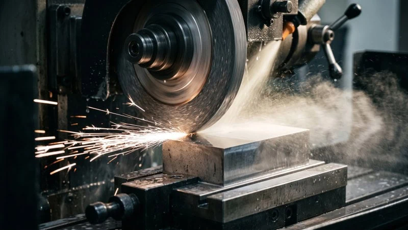
Understanding the 11V9 Flaring Cup Wheel
What makes the 11V9 flaring cup wheel essential for precision machining?
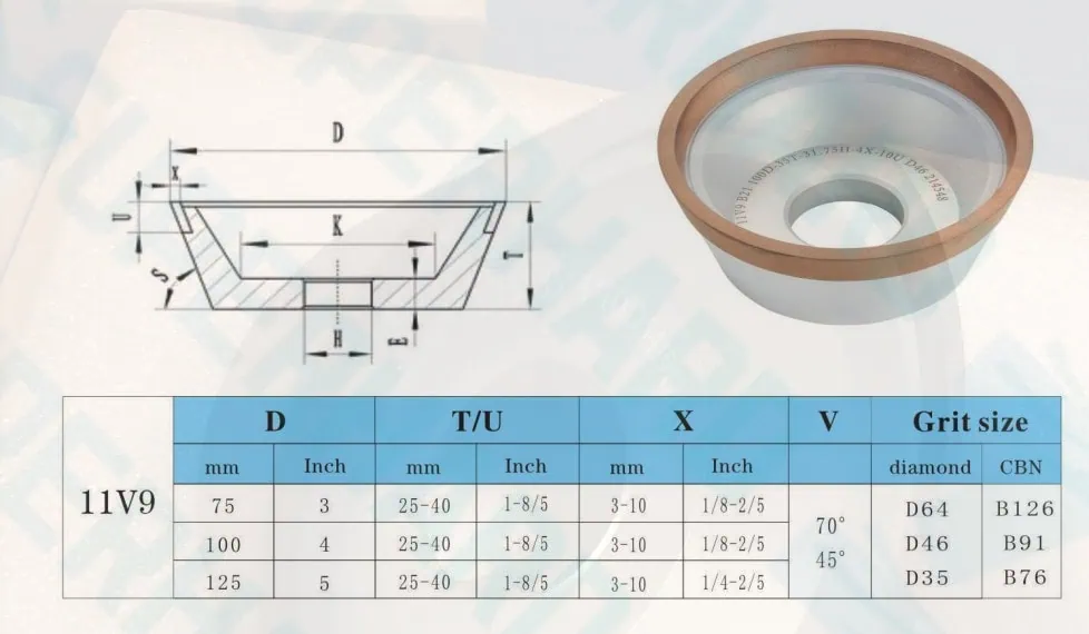
The 11V9 is a flaring cup wheel with a tapered core, featuring an angled abrasive profile located strictly on its rim. This specific flared geometry provides exceptional structural rigidity, making it the industry standard for tool sharpening and complex cutter grinding without risking spindle collision.
Why Rigidity Matters in 11V9 Designs
Rigidity is the most critical factor in precision tool grinding. When a wheel deflects, it ruins the surface finish and destroys dimensional accuracy. The 11V9 wheel combats this problem perfectly.
Its core shape flares outward from the center hub. This creates a highly stable, triangulated base. Think of it like a heavy-duty Morse taper shank8 on a milling machine. The tapered design distributes radial cutting forces evenly across the wheel body. Consequently, this prevents the abrasive edge from bending during heavy cuts.
“In professional CNC tool rooms, eliminating wheel deflection is non-negotiable for producing tight-tolerance carbide tooling.”
The core material heavily dictates this overall stiffness. Steel provides the absolute highest rigidity for heavy stock removal. However, resin and aluminum cores absorb vibration and reduce spindle wear. Core materials and taper angles can be customized based on specific machine tool clearances to maximize this rigidity for specialized tasks.
Ideal Grinding Operations for 11V9
The 11V9 wheel is built specifically for creating sharp, precise cutting edges. The angled “V” profile allows the wheel to access tight, complex geometries. Meanwhile, placing the abrasive squarely on the rim (“9”) lets the machinist approach the workpiece at steep, aggressive angles.
As a result, it remains the primary tooling choice for CNC tool and cutter grinders9. Machinists rely on it daily to manufacture and resharpen complex industrial tools.
| Machining Operation | Specific Shop Floor Application | Common Workpiece Material |
|---|---|---|
| Top Grinding | Sharpening the top faces of circular saw blades. | Tungsten Carbide10 Inserts |
| Relief Angle Grinding | Creating primary and secondary clearance angles on end mills. | High-Speed Steel (HSS) |
| Flute Maintenance | Cleaning and re-profiling the cutting flutes of step drills. | Solid Carbide Blanks |
Why is it so effective for relief angles? When grinding the back angle of an end mill, the grinding wheel must not hit the adjacent cutting tooth. The flared cup design of the 11V9 provides excellent physical clearance. The machine spindle stays safely elevated away from the tool fixture. Consequently, operators can grind aggressive relief angles in a single setup without causing tool collisions.
The 12V9 Dish Wheel and Its Unique Clearance
Why is the 12V9 dish wheel the preferred choice when machining clearance is exceptionally tight?
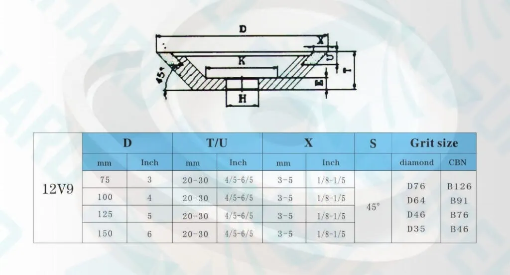
The 12V9 is a dish-shaped grinding wheel featuring an angled abrasive profile on its rim. Its shallow, swept-back core geometry provides significantly more lateral clearance than flaring cup designs, making it essential for grinding fine tooth pitches on saws and intricate end mills where adjacent teeth would otherwise cause collisions.
11V9 vs 12V9: Key Structural Differences
Machinists frequently confuse the 11V9 and the 12V9 because they share the same angled rim profile (“V9”). However, the core geometry completely changes how they operate on the shop floor.
The 11V9 uses a thick, flaring cup shape. This provides massive structural rigidity, but the bulky core can interfere with tight spaces. Conversely, the 12V9 utilizes a distinct “dish” shape. Think of the 12V9 core like a low-profile lathe faceplate. It is much shallower and sweeps dramatically away from the abrasive edge.
This swept-back design aggressively pushes the inflection point outward. Consequently, the abrasive rim protrudes further away from the main body of the wheel.
| Feature | 11V9 Flaring Cup | 12V9 Dish Wheel |
|---|---|---|
| Core Shape | Deep, tapered cup | Shallow, swept-back dish |
| Lateral Clearance | Moderate | Excellent / Maximum |
| Primary Strength | Extreme rigidity under load | Unrestricted access in tight pitches |
Because dish angles and specific hub depths vary between wheel manufacturers, always confirm these exact core dimensions during programming to ensure safe spindle clearance.
When to Choose 12V9 for Tool Sharpening
You should select a 12V9 wheel specifically when working with small-diameter tools or dense tooth configurations. In these scenarios, avoiding a crash between the grinding wheel core and the workpiece is your primary concern.
For example, when a CNC operator grinds the back angles on a fine-pitch circular saw blade, the space between the teeth is minimal. An 11V9 wheel would likely clip the neighboring tooth, ruining the blade. The 12V9 dish shape effortlessly drops into that narrow gap.
- Fine-Pitch Saws: Face grinding circular saw blades where adjacent teeth sit closely together.
- Complex End Mills: Completing both the end tooth and circumferential back angles on multi-flute end mills in a single, continuous setup.
- Woodworking Tooling: Sharpening router bits where the cutter geometry requires an aggressive approach angle.
Ultimately, whenever your spindle setup struggles to reach the cutting surface without colliding with other parts of the tool, the 12V9 is your immediate solution.
How to Select the Right Abrasive Wheel for Your Setup
How do you determine the exact grinding wheel specification required for your specific machining environment?
Selecting the correct abrasive wheel requires matching the basic FEPA shape directly to your machine’s kinematic limits and the workpiece geometry. Operators must evaluate spindle horsepower, coolant delivery, and physical clearance to prevent structural deflection. Furthermore, you must define the exact outer diameters, bore sizes, and grit concentrations to guarantee precision surface finishes.
Matching Wheel Geometry to CNC Tool Grinders
When programming a 5-axis CNC tool grinder, the physical wheel must perfectly match the digital simulation. If you program a flat cutting profile but mount a tapered cup, the machine spindle will likely crash. Therefore, matching physical geometry to the software is a critical first step.
Just as a machinist matches a specific boring bar’s overhang to a lathe’s internal clearance, you must align the wheel’s core profile with your machine’s spindle housing. Modern CNC grinders utilize software packages to build digital wheel packs. You must input the exact wheel geometry into this software system. This crucial step ensures the machine calculates toolpaths correctly. Consequently, it avoids expensive spindle collisions during complex automated interpolations.
Preventing Deflection and Surface Finish Issues
Deflection11 is the absolute enemy of precision grinding. When a wheel bends under cutting pressure, it creates visible chatter marks. This ruins the final surface finish and causes severe dimensional inaccuracies on the workpiece.
This mechanical issue acts exactly like tool deflection in traditional milling. If you push an extended end mill too hard, it vibrates aggressively. Similarly, a thin grinding wheel edge will chatter during fast feed rates. To prevent this, you must prioritize core stiffness. Choose solid steel cores for heavy roughing applications. Additionally, ensure your high-pressure coolant nozzles aim directly at the primary grinding zone. Proper fluid cooling12 reduces thermal expansion. This keeps the wheel structurally stable and prevents workpiece burning.
Specifying Dimensions Beyond the Basic Shape Code
The standard FEPA code only dictates the general wheel shape. It does not provide the physical measurements required to physically mount the wheel. Therefore, you must specify several precise dimensions to complete your setup.
| Dimension Code | Technical Definition | Application Importance |
|---|---|---|
| Outer Diameter (D) | The total maximum width of the wheel body. | Must fit inside the machine’s safety guards and tool changer. |
| Bore Size (H) | The diameter of the center mounting hole. | Secures the wheel perfectly onto the machine’s spindle arbor. |
| Abrasive Width (W) | The actual width of the active cutting layer. | Determines the maximum contact area with the workpiece. |
| Abrasive Depth (X) | The total thickness of the usable diamond or CBN grit. | Dictates the overall operational lifespan of the wheel. |
Because these specific dimensional parameters and abrasive depth limits frequently vary based on custom spindle requirements and target material hardness, you should always verify the exact range and details with your abrasive supplier. Securing these precise measurements ensures the grinding wheel balances correctly and runs smoothly at high operating RPMs.
Conclusion
Understanding the structural differences between 1A1, 11V9, and 12V9 wheel shapes is essential for optimizing your grinding operations. By decoding the FEPA standardization, machinists can eliminate guesswork, prevent costly spindle collisions, and ensure superior surface finishes on complex tooling. Whether you need the heavy-duty stock removal of a straight wheel, the rigidity of a flaring cup, or the unparalleled clearance of a dish shape, matching the exact geometry to your specific CNC setup guarantees better efficiency and extended tool life. To ensure you order the precise wheel specifications for your next production run, please contact us for expert guidance.
References
- diamond and CBN grinding wheels1 – ZYDiamondTools product category showcasing various types of diamond and CBN grinding wheels.
- CNC milling center2 – Wikipedia entry detailing Computer Numerical Control in modern milling operations.
- surface grinding3 – Wikipedia article explaining the surface grinding process used to produce flat, smooth finishes.
- cylindrical grinding4 – ZYDiamondTools article covering selection and case studies for diamond cylindrical grinding operations.
- plain milling cutter5 – Wikipedia overview of various milling cutters, including plain geometries used in standard machining.
- High-Speed Steel (HSS)6 – Wikipedia page detailing the composition and applications of high-speed steel in toolmaking.
- Centerless grinding7 – ZYDiamondTools ultimate guide to selecting wheels for centerless grinding processes.
- Morse taper shank8 – Wikipedia explanation of the Morse machine taper system used to mount tool holders rigidly.
- tool and cutter grinders9 – Wikipedia definition of grinding machines specifically designed to sharpen milling cutters and tool bits.
- Tungsten Carbide10 – Wikipedia comprehensive overview of tungsten carbide material properties and machining uses.
- Deflection11 – Wikipedia page on engineering deflection, crucial for understanding structural rigidity during cutting.
- fluid cooling12 – ZYDiamondTools post explaining the top 5 critical reasons for utilizing proper coolant in surface grinding.