-
Whatsapp: +86 13526572721
-
Email: info@zydiamondtools.com
-
Address: AUX Industrial Park, Zhengzhou City, Henan Province, China
-
Whatsapp: +86 13526572721
-
Email: info@zydiamondtools.com
-
Address: AUX Industrial Park, Zhengzhou City, Henan Province, China

What are the Optimal Cutting Parameters for PCD Reamers? (Finding Speeds, Feeds & Best Practices)

What does it really take to find and use the best cutting parameters for your PCD reamers to get top performance?
Achieving optimal results with PCD reamers hinges on understanding how to determine correct starting speeds and feeds based on material and calculations, recognizing the key factors that influence parameter selection (like material properties, tool design, machine stability, and coolant), and consistently applying best practices for setup, optimization, and troubleshooting.
How Do You Determine Starting Speeds and Feeds for PCD Reamers?
So, how exactly do you figure out the right starting speed and feed rate when you’re about to use a PCD reamer?
Finding the ideal starting point involves checking recommended parameter ranges based on the material you’re cutting, understanding how cutting speed (Vc) and feed rate (f) work, knowing how to calculate them for your machine, and utilizing data directly from the tool manufacturer.
Let’s break down each of these steps to get you started safely and effectively.
Recommended Parameter Ranges by Workpiece Material (Aluminum Alloys, Composites, etc.)
Different materials behave differently when cut. Think about cutting soft wood versus hard metal – you’d use different speeds and pressures, right? It’s the same idea here. PCD reamers work best on specific materials, mainly non-ferrous metals (like aluminum) and abrasive non-metals (like composites).
The most important step is to know the specific material you are machining. Is it an aluminum alloy like AlSi7Mg (A356)? Or perhaps a carbon fiber reinforced polymer (CFRP)1? Each requires different starting parameters.
Here’s a general idea of typical starting ranges. Remember, these are starting points only, and can vary significantly based on the exact alloy, the specific PCD tool design, and machine conditions.
| Workpiece Material Category | Typical Starting Cutting Speed (Vc) Range | Typical Starting Feed Rate (f) Range (per revolution) | Notes |
|---|---|---|---|
| Aluminum Alloys (Low Silicon) | 150 – 600 m/min (approx. 500 – 2000 SFM) | 0.10 – 0.40 mm/rev (approx. 0.004 – 0.016 in/rev) | Higher speeds often possible with good cooling & machine stability. |
| Aluminum Alloys (High Silicon) | 100 – 400 m/min (approx. 330 – 1300 SFM) | 0.08 – 0.30 mm/rev (approx. 0.003 – 0.012 in/rev) | Silicon is abrasive; may require slightly lower Vc for tool life. |
| Carbon Fiber Composites (CFRP) | 50 – 200 m/min (approx. 160 – 650 SFM) | 0.05 – 0.20 mm/rev (approx. 0.002 – 0.008 in/rev) | Focus on clean cutting edges; delamination is a key concern. |
| Metal Matrix Composites (MMC) | 50 – 150 m/min (approx. 160 – 500 SFM) | 0.05 – 0.15 mm/rev (approx. 0.002 – 0.006 in/rev) | Highly abrasive; requires careful parameter selection. |
Important Reminder: These ranges are general guidelines. Always consult your specific PCD tool supplier for their precise recommendations based on the exact tool geometry, PCD grade, and your specific material grade and condition. Their data sheets often provide much more targeted starting values.
Understanding Cutting Speed (Vc) Recommendations and Calculations (RPM)
What exactly is cutting speed, or Vc? Imagine the edge of the reamer spinning. Cutting speed (Vc) is how fast a single point on the reamer’s cutting edge travels as it cuts the material surface. It’s usually measured in meters per minute (m/min) or surface feet per minute (SFM).
Think of it like the speed of a car’s tire surface moving against the road, not how fast the car itself is traveling forward. Higher Vc generally means faster cutting, but also generates more heat. Finding the right Vc balances speed with managing heat and tool wear.
Why Vc Matters
Choosing the right Vc is crucial because it directly affects:
- Tool Life: Too high Vc generates excessive heat, potentially damaging the PCD edge or the brazed joint holding it.
- Surface Finish: An appropriate Vc helps achieve a smooth, clean cut surface. Too low might cause rubbing, while too high might cause thermal damage.
- Hole Quality: Correct speed helps maintain size and prevent issues like built-up edge (material sticking to the tool).
Calculating Spindle Speed (RPM) from Vc
Your machine tool doesn’t directly use Vc. You need to set the spindle speed, measured in revolutions per minute (RPM). You calculate RPM using the cutting speed (Vc) and the reamer’s diameter (D).
Here are the formulas, commonly found in engineering resources like Machinery’s Handbook and online calculators:
- Metric (Vc in m/min, D in mm):
RPM = (Vc * 1000) / (π * D)
(Where π ≈ 3.14159) - Imperial (Vc in SFM, D in inches):
RPM = (Vc * 12) / (π * D)or simplified often asRPM = (Vc * 3.82) / D
Example: Let’s say your supplier recommends a starting Vc of 300 m/min for an aluminum alloy, and your PCD reamer has a diameter (D) of 10 mm.
RPM = (300 * 1000) / (3.14159 * 10) ≈ 300000 / 31.4159 ≈ 9549 RPM
You would set your machine’s spindle speed close to 9550 RPM as a starting point.
Understanding Feed Rate (f) Recommendations and Calculations (mm/min or inch/min)
If cutting speed is how fast the edge spins against the material, feed rate (f) is how quickly the reamer advances along the hole’s axis. Think of it like how fast you push a drill into wood.
Feed rate is usually given in two ways:
- Feed per revolution (fn or fz): This is the distance the tool advances in one single revolution of the spindle. It’s often measured in millimeters per revolution (mm/rev) or inches per revolution (in/rev). This is usually the value you find in parameter tables. Sometimes it might be specified as feed per tooth (fz), which you then multiply by the number of flutes (z) to get feed per revolution (fn = fz * z).
- Feed rate (Vf): This is the linear speed the tool advances into the workpiece, usually measured in millimeters per minute (mm/min) or inches per minute (in/min). This is the value you typically enter into the CNC machine controller.
Why Feed Rate Matters
The feed rate influences:
- Cycle Time: Higher feed rates mean the hole is finished faster.
- Surface Finish: Too high a feed rate can leave noticeable feed marks, resulting in a rougher surface. Too low might cause rubbing and unnecessary wear.
- Chip Formation: Feed rate affects the thickness of the chip removed by each cutting edge.
- Tool Pressure: Higher feed rates increase the cutting forces.
Calculating Feed Rate (Vf) from Feed per Revolution (fn)
To get the value your machine needs (Vf), you use the feed per revolution (fn) and the spindle speed (RPM) you calculated earlier.
The formula is simple:
- Vf (mm/min) = fn (mm/rev) * RPM
- Vf (inch/min) = fn (inch/rev) * RPM
Example (Continuing from before): We calculated an RPM of 9549. Let’s say the recommended feed per revolution (fn) for our 10 mm reamer in this aluminum is 0.15 mm/rev.
Vf = 0.15 mm/rev * 9549 rev/min ≈ 1432 mm/min
You would program your machine with a feed rate of approximately 1432 mm/min.
Leveraging Manufacturer Data Sheets and Online Calculators
Where do you find reliable starting Vc and fn values? While general tables (like the one above) give you an idea, the absolute best source is the manufacturer of your specific PCD reamer.
Why Manufacturer Data is Crucial
- Tool Specificity: Manufacturers design tools with specific geometries, PCD grades, and edge preparations. Their recommendations are tailored to their tools, ensuring optimal performance and avoiding damage. Using generic parameters on a highly specialized tool might lead to poor results or premature failure.
- Material Testing: Reputable manufacturers invest heavily in testing their tools on various workpiece materials. Their data sheets reflect these real-world results.
- Latest Information: Materials and tool technology evolve. Manufacturer data is typically the most up-to-date.
Where to Find Manufacturer Data
- Tool Catalogs: Printed or digital catalogs almost always contain extensive parameter tables categorized by tool series and workpiece material.
- Manufacturer Websites: Most manufacturers offer online resources, including downloadable catalogs, technical data sheets for specific tools, and sometimes online parameter calculators.
- Tooling Representatives/Technical Support: Don’t hesitate to contact the manufacturer’s technical support or sales engineers. They can provide specific advice for your application, especially if it’s challenging or involves non-standard materials.
Using Online Calculators
Many tool manufacturers and some independent tooling sites offer online “speeds and feeds” calculators. These can be very convenient:
- You typically input the tool type (reamer), tool diameter, workpiece material, and sometimes the specific operation.
- The calculator automatically suggests starting Vc, fn, RPM, and Vf.
- Caution: Ensure the calculator is from a reputable source (ideally the tool manufacturer). Always treat the results as starting points and be prepared to adjust based on actual cutting performance.
By understanding these core concepts – checking material recommendations, knowing what Vc and feed mean, performing the simple calculations, and prioritizing manufacturer data – you can confidently determine safe and effective starting parameters for your PCD reaming operations. Remember, these are starting points; the next steps involve careful testing and optimization, which we’ll discuss later.

What Key Factors Influence PCD Reaming Parameter Selection?
Beyond just knowing the starting points, what actually causes you to adjust those initial speeds and feeds for PCD reamers?
Several critical factors significantly impact your choice of optimal PCD reaming parameters, including the specific workpiece material’s properties, the reamer’s own design features, the capabilities and condition of your machine tool, the effectiveness of your coolant strategy, and the final quality requirements for the hole.
Understanding these factors is key to moving beyond basic recommendations and truly optimizing your reaming process. Let’s explore each one.
Impact of Workpiece Material Hardness and Abrasiveness
The material you’re cutting is arguably the biggest influence. Just like you wouldn’t use the same knife pressure to cut butter as you would frozen meat, different materials require different approaches.
- Hardness: This is how resistant the material is to scratching or denting, often measured using scales like Rockwell or Vickers. Harder materials generally require lower cutting speeds (Vc) and sometimes lower feed rates (f) to avoid excessive tool wear and heat generation. For example, while you might run high speeds on a standard aluminum casting, a harder, heat-treated aluminum alloy might require pulling back the Vc.
- Abrasiveness: This refers to how much the material tends to wear away the cutting tool, like sandpaper. Some materials contain hard particles that act like tiny grinders on the PCD edge. Understanding abrasive wear2 mechanisms is key.
- High-silicon aluminum alloys (often used in engine blocks) are notoriously abrasive due to the hard silicon particles. You’ll typically need lower Vc compared to low-silicon aluminum to manage tool wear.
- Metal Matrix Composites (MMCs), which mix metal with hard reinforcements like ceramic particles, are extremely abrasive and demand significantly reduced speeds and feeds to achieve acceptable tool life.
- Even some plastics or composites can be surprisingly abrasive.
Ignoring hardness and abrasiveness can lead to rapid tool wear, poor surface finish, and inaccurate holes.
Influence of PCD Reamer Design (Diameter, Flute Count, Geometry)
The design of the PCD reamer itself plays a huge role. Think of different types of car tires – some are built for speed, others for grip, others for durability. Reamers are similar.
- Diameter (D): Larger diameter reamers generally run at lower RPM for the same cutting speed (Vc), as seen in the RPM formula. They also tend to be more rigid, which can sometimes allow for slightly more aggressive feed rates.
- Number of Flutes (z): Reamers can have different numbers of cutting edges (flutes).
- More flutes mean the feed load is distributed over more edges. This can allow for a higher table feed rate (Vf) while maintaining a reasonable chip load per tooth (fz). For instance, a 6-flute reamer might achieve the same quality at a higher Vf than a 4-flute reamer, assuming the machine can handle it and chips can be cleared effectively.
- However, more flutes also mean less space between them for chips to escape, making effective coolant and chip evacuation even more critical, especially in blind holes.
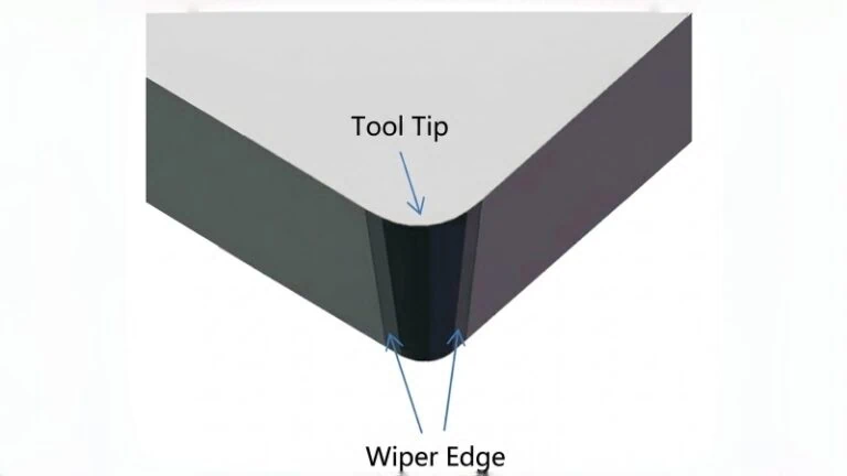
- Geometry: This includes details like the cutting edge angle, helix angle (if any), margin design, and the specific grade of PCD used.
- Different geometries are optimized for specific materials or outcomes (e.g., some designs minimize burrs in aluminum, others are built for maximum wear resistance in composites).
- The PCD grade itself (referring to the size of the diamond crystals and the binder) impacts toughness and wear resistance, influencing optimal Vc and feed.
Key Takeaway: The reamer’s design directly impacts its ideal operating window. It’s crucial to consider the specific design features, and referencing the manufacturer’s guidance for that particular tool design is essential, as parameters can differ even between tools of the same diameter from different makers or series.
Role of Machine Tool Rigidity and Spindle Power/Speed Limits
Your machine tool is the foundation of the entire operation. Its capabilities heavily influence the parameters you can realistically use.
- Rigidity: This refers to the machine’s ability to resist deflection or vibration under cutting forces, encompassing both static and dynamic rigidity.
- Imagine trying to write neatly on a wobbly table versus a solid workbench. A less rigid machine will vibrate more easily.
- Vibration is detrimental to reaming, causing poor surface finish, inconsistent hole size, chatter marks, and reduced tool life.
- On machines with lower rigidity, you generally need to use more conservative (lower) cutting speeds and feed rates to minimize cutting forces and prevent vibration. High-performance reaming demands a robust, well-maintained machine.
- Spindle Power: Reaming, especially at higher speeds and feeds, requires adequate spindle power to maintain the programmed RPM without bogging down. Undersized spindles might limit the achievable material removal rates.
- Spindle Speed Limits (Max RPM): Your machine has a maximum RPM. This can sometimes be a limiting factor, especially when using small diameter reamers in materials where a very high Vc is recommended. You might calculate a required RPM that exceeds the machine’s capability, forcing you to run at a lower-than-ideal Vc.
Criticality of Coolant Type, Pressure, and Delivery Method
Coolant (cutting fluid) is not just optional in most PCD reaming; it’s often critical. It performs several vital jobs:
- Cooling: Reduces heat generated at the cutting zone, protecting the PCD edge and the workpiece material. Excessive heat can cause dimensional changes and tool damage.
- Lubrication: Reduces friction between the tool, chip, and workpiece.
- Chip Evacuation: Flushes chips away from the cutting edges and out of the hole. This is extremely important in reaming to prevent chips from jamming, recutting, or damaging the finished surface.
The effectiveness depends on:
- Coolant Type: Water-soluble coolants (emulsions or synthetics) are common for aluminum. The specific formulation matters for lubricity and cooling properties. Resources like the Society of Tribologists and Lubrication Engineers (STLE)3 offer insights into fluid types. Always ensure the coolant is compatible with both the workpiece material and the PCD tool itself. Some aggressive coolant chemistries could potentially attack the binder material in certain PCD grades over time, though this is less common with modern formulations when properly managed. Check with both your coolant and tool supplier if unsure.
- Concentration: Maintaining the correct coolant concentration (mix ratio) is vital for performance.
- Pressure and Flow Rate: Sufficient pressure and flow volume are needed to effectively flush chips out, especially in deep holes or with multi-flute reamers where chip space is limited. Think of a weak garden hose versus a pressure washer trying to clear debris. High-pressure through-spindle coolant is often ideal for demanding reaming applications.
- Delivery Method: Where is the coolant aimed? Through-spindle coolant delivers it directly to the cutting zone. External nozzles must be carefully positioned to ensure coolant reaches the cutting edges effectively and aids chip evacuation.
Inadequate coolant application often necessitates reducing speeds and feeds to manage heat and prevent chip packing, directly impacting productivity and quality.
Effect of Required Surface Finish (Ra) and Hole Tolerance Demands
Finally, what quality level do you need to achieve? The required precision directly influences parameter choices.
- Surface Finish (Ra): This measures the average roughness of the reamed hole surface (lower Ra means smoother), defined by standards like ISO 21920-24.
- Generally, lower feed rates (f) tend to produce smoother finishes, as the tool marks left by each revolution are closer together.
- Extremely high cutting speeds (Vc) might sometimes negatively impact finish due to thermal effects, while very low speeds might cause rubbing instead of clean cutting. Finding the “sweet spot” is key.
- Hole Tolerance: This refers to the allowable variation in the final hole diameter (e.g., +/- 0.01 mm), often specified using systems like the ISO System of Limits and Fits.
- Achieving very tight tolerances requires stable cutting conditions. This often means using moderate, well-controlled speeds and feeds rather than pushing for maximum speed.
- Factors like heat generation (which can cause the hole to expand during cutting and contract afterward) and vibration need to be minimized, often favoring slightly less aggressive parameters.
- Consistent coolant application is also critical for thermal stability and tolerance control.
If your goal is simply a functional hole within a wide tolerance, you might prioritize higher speeds and feeds for productivity. However, if you need a mirror-like finish and micron-level accuracy, you’ll likely need to adjust parameters more conservatively and focus heavily on stability, coolant, and tool condition.

What are the Best Practices for Applying PCD Reaming Parameters Effectively?
Now that you know how to find starting parameters and what factors influence them, how do you actually put this knowledge into practice effectively for the best results?
Applying PCD reaming parameters effectively involves ensuring a precise and stable setup (tool holding, alignment, minimal runout), systematically testing and optimizing parameters from the starting point, guaranteeing optimal coolant delivery, recognizing and troubleshooting common issues promptly, and using PCD reamers in the applications where they truly excel.
Following these best practices helps you maximize performance, achieve desired quality, and extend the life of your valuable PCD tools. Let’s dive into the details.
Ensuring Proper Tool Holding, Alignment, and Minimal Runout
A stable foundation is crucial before you even start cutting. Think of it like trying to hit a target accurately – if your stance is unstable, your aim will be off.
- Tool Holding: Use high-quality, precision tool holders designed for reaming. Hydraulic chucks, high-precision collet chucks, or shrink-fit holders are often recommended. These provide strong, uniform clamping force and minimize wobble. Avoid using worn-out or lower-precision holders (like standard ER collets for roughing) for finishing operations like reaming.
- Alignment: Ensure the reamer is perfectly aligned with the axis of the pre-drilled hole and the machine spindle. Misalignment forces the reamer to cut unevenly, leading to poor hole quality, bell-mouthing (the hole entrance being too wide), and excessive tool wear.
- Minimal Runout: Runout refers to the wobble or off-center rotation of the tool as the spindle turns. Imagine a slightly bent wheel on a car – it doesn’t roll smoothly. For precision reaming, especially with PCD tools, runout must be extremely low.
- What causes runout? It can come from the spindle itself, the tool holder, improper tool clamping, or even a bent tool shank.
- Why it matters? High runout means one cutting edge might take a much heavier cut than the others, leading to vibration, poor finish, inaccurate size, and drastically reduced tool life.
- Target: Aim for runout measured at the tool tip to be as low as possible, ideally below 0.005 mm (0.0002 inches), or even better for critical applications. Always check runout with a dial indicator after mounting the tool in the machine.
A precise setup is non-negotiable for successful PCD reaming. Spending time here prevents many downstream problems.
Strategies for Initial Parameter Testing and Gradual Optimization
The parameters you get from datasheets or calculators are just starting points. You’ll likely need to fine-tune them for your specific machine, material batch, and quality requirements. Optimization is about finding the best balance between productivity, quality, and tool life.
Here’s a systematic approach:
- Start Conservatively: Begin with the recommended starting parameters from the tool manufacturer. If unsure, it’s often safer to start with slightly lower Vc and feed.
- Machine a Test Hole: Ream one or a few holes using the starting parameters.
- Evaluate the Result: Carefully inspect the hole(s) for:
- Size: Is it within the required tolerance? Measure accurately.
- Surface Finish (Ra): Does it meet the smoothness specification? Check visually and with measuring equipment if needed.
- Tool Condition: Examine the PCD cutting edges (safely, after stopping the machine) for any signs of chipping, excessive wear, or material buildup.
- Adjust Parameters Incrementally: Based on the evaluation, make small, controlled adjustments.
- If quality is good and tool wear is minimal: You might cautiously increase the feed rate (f or Vf) in small increments (e.g., 10-15%) to improve productivity. Re-evaluate after each increase.
- If surface finish needs improvement: You might try slightly decreasing the feed rate (f) or adjusting the cutting speed (Vc) modestly (up or down) to find a smoother cutting action.
- If tool wear is too fast: Consider decreasing the cutting speed (Vc) first, as heat is often a major factor in wear.
- If hole size is off: This could be due to various factors (runout, thermal expansion, parameter issues). Stable parameters are key; avoid drastic changes if size is the only issue initially – check setup first.
- Document Findings: Keep records of the parameters used and the results achieved. This helps build knowledge for future jobs.
Optimization is an iterative process. Change only one parameter at a time to understand its effect. The goal is to find the “sweet spot” for your specific application.
Optimizing Coolant Application for Effective Cooling and Chip Evacuation
We discussed why coolant is critical earlier. Here’s how to ensure it’s working effectively:
- Verify Concentration: Regularly check and maintain the correct coolant mix ratio using a refractometer. Incorrect concentration affects cooling, lubrication, and tool life.
- Ensure Adequate Flow and Pressure: Don’t guess! Ensure the flow rate and pressure are sufficient to vigorously flush chips out of the hole and away from the cutting zone. Weak flow allows chips to be recut, damaging the finish and tool.
- Through-Spindle Coolant: If available, this is often the most effective method, delivering coolant directly to the point of cut. Ensure the passages are clear.
- External Nozzles: Position them carefully. Aim multiple nozzles strategically to flood the cutting zone and create a flushing action directed out of the hole. Consider the direction of tool rotation and chip flow.
- Filtration: Keep your coolant clean. Contaminated coolant with fine abrasive particles can negate the benefits and even harm the tool or surface finish. Ensure proper filtration is in place and maintained.
Effective coolant application is essential for controlling heat and managing chips during PCD reaming.
Recognizing and Troubleshooting Common Issues (Poor Finish, Rapid Wear, Size Control)
Even with best practices, problems can arise. Quickly identifying the likely cause is key to fixing them.
Addressing Poor Surface Finish
- Check Runout First: This is a very common culprit. Re-check and minimize tool runout.
- Verify Coolant: Is flow adequate? Is concentration correct? Are chips being flushed effectively? Chip recutting severely degrades finish.
- Adjust Feed Rate: Too high a feed leaves prominent marks. Try reducing feed per revolution (f). Sometimes, too low a feed can cause rubbing; a slight increase might help.
- Adjust Cutting Speed: Experiment modestly with Vc (up or down from current setting) to find a smoother cutting action.
- Examine Tool Edge: Is there built-up edge (material welded to the tip)? Is the edge chipped or worn? A damaged tool cannot produce a good finish.
Tackling Rapid Tool Wear
- Reduce Cutting Speed (Vc): This is the primary way to reduce heat, a major driver of wear, especially in abrasive materials.
- Improve Cooling: Ensure efficient coolant delivery right at the cutting edge.
- Check Material Abrasiveness: Are you dealing with high-silicon aluminum, MMC, or an abrasive composite? Your parameters might be too aggressive for the material.
- Verify PCD Grade: Is the PCD grade suitable for the application? Some grades are tougher, others more wear-resistant. Consult your tool supplier if wear seems excessive despite reasonable parameters.
- Minimize Runout: Uneven cutting loads caused by runout accelerate wear on the overloaded edges.
Solving Hole Size Inaccuracies
- Check Runout: High runout often leads to oversized holes.
- Measure Tool Diameter Accurately: Verify the actual diameter of the reamer.
- Ensure Machine/Setup Stability: Vibration or deflection during cutting can affect size. Revisit machine rigidity and tool holding.
- Manage Thermal Expansion: Is the part getting too hot during reaming? Improved cooling might be needed to prevent the hole from being cut oversized while hot, then shrinking undersized when cool. Consistent coolant is key.
- Check Feed Rate: While less common, extremely high or low feed rates under certain conditions might slightly influence size due to cutting pressure variations. Focus on stable, moderate feeds.
- Reamer Wear: A worn reamer (especially on the margins or guiding chamfers) will eventually start cutting undersized.
Troubleshooting requires a logical approach. Start with the easiest things to check (like runout and coolant) before making major parameter changes.
Identifying Ideal Applications Where PCD Reamers Excel
While versatile within their niche, PCD reamers aren’t suitable for everything. Knowing where they shine helps you apply them effectively:
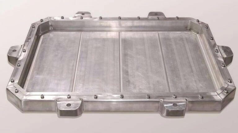
- High-Volume Production of Non-Ferrous Metals: Especially aluminum alloys (cast, wrought, high-silicon). PCD offers significantly longer tool life compared to carbide in these materials, reducing tool change downtime and cost per hole in mass production (e.g., automotive engine and transmission components). See a comparison here: PCD vs Carbide Tools5.
- Machining Abrasive Non-Metals: Carbon fiber composites (CFRP), glass fiber composites (GFRP), graphite, ceramics (in green state), and metal matrix composites (MMC). The extreme hardness of PCD provides superior wear resistance against these abrasive materials where carbide tools wear out very quickly.
- Applications Requiring High Precision and Surface Finish: When properly applied, PCD can produce excellent surface finishes and hold tight tolerances over long production runs due to its edge stability and wear resistance.
- Cost-Sensitive Operations (Total Cost): While the initial cost of a PCD reamer is higher than carbide, its vastly longer tool life in the right application often leads to a lower total cost per hole6 due to fewer tool changes, less downtime, and consistent quality.
PCD reamers are generally NOT the first choice for:
- Ferrous materials (steels, cast iron) – Chemical reactions typically lead to rapid tool failure.
- Operations with heavy interruptions or extreme instability.
- Very low volume jobs where the initial tool cost cannot be justified by tool life savings.
By focusing on these best practices – meticulous setup, systematic optimization, effective cooling, proactive troubleshooting, and applying the tools in their ideal applications – you can unlock the full potential of PCD reamers for high-quality, efficient production.
Conclusion
Successfully using PCD reamers goes beyond simply knowing basic speeds and feeds. It requires a holistic approach: finding reliable starting points from manufacturer data, understanding how material properties, tool design, machine condition, coolant, and quality needs influence parameter choices, and diligently applying best practices in setup, testing, optimization, and troubleshooting. By mastering these elements, you can leverage the unique advantages of PCD tooling to achieve exceptional precision, surface finish, and tool life, particularly in demanding non-ferrous and composite materials.
References
- carbon fiber reinforced polymer (CFRP)1 – ZYDiamondTools blog post discussing the use of PCD tools for machining aerospace composites like CFRP.
- abrasive wear2 – ScienceDirect topic page providing scientific context and articles on abrasive wear mechanisms.
- Society of Tribologists and Lubrication Engineers (STLE)3 – Homepage of STLE, a professional society providing resources on lubrication and cutting fluids.
- ISO 21920-24 – ISO (International Organization for Standardization) page for the standard defining surface texture parameters like Ra.
- PCD vs Carbide Tools5 – ZYDiamondTools blog post comparing PCD and Carbide cutting tools.
- total cost per hole6 – ZYDiamondTools guide explaining the TCO concept and application for superhard tooling & abrasives.