-
Whatsapp: +86 13526572721
-
Email: info@zydiamondtools.com
-
Address: AUX Industrial Park, Zhengzhou City, Henan Province, China
-
Whatsapp: +86 13526572721
-
Email: info@zydiamondtools.com
-
Address: AUX Industrial Park, Zhengzhou City, Henan Province, China

CBN Chipbreaker Inserts: How to Select and Apply Them for Optimal Hard Material Machining?
What are CBN chipbreaker inserts, and why is selecting the correct geometry critical for the efficiency and safety of hard turning operations?
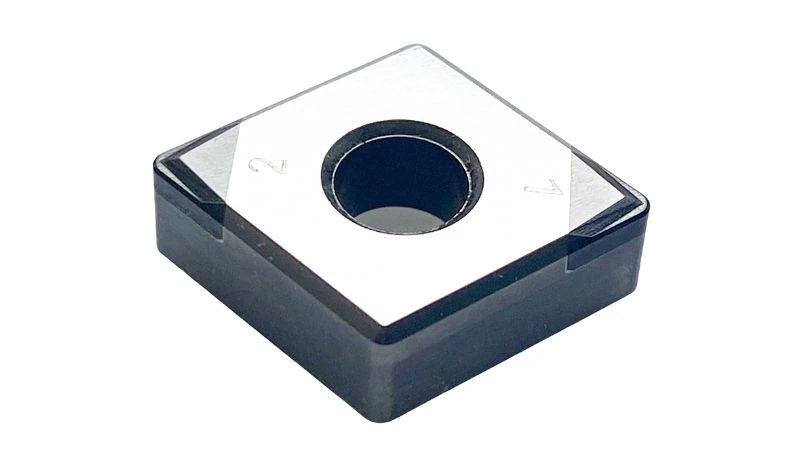
CBN Chipbreaker Inserts1 are specialized polycrystalline cubic boron nitride cutting tools engineered with specific 3D top geometries to mechanically curl and fracture the tough, continuous chips generated when machining hardened steel (HRC 50–65). Selecting the correct geometry is critical because it prevents dangerous “bird nesting,” protects automated equipment from jamming, and ensures consistent surface finishes by managing the intense heat and high rigidity of hardened steel chips.
Why Traditional Flat Top PCBN Inserts Fail in Hard Turning
Why do standard flat top PCBN inserts struggle to manage chips when machining hardened steel components?
Traditional flat top PCBN inserts lack the physical geometry required to curl and stress the chip until it fractures. In hard turning2, the material produces continuous, high-strength chips that slide unobstructed across a flat rake face. This results in long, stringy ribbons that wrap around the tool holder and workpiece, causing surface damage, unpredictable downtime, and safety hazards for operators.
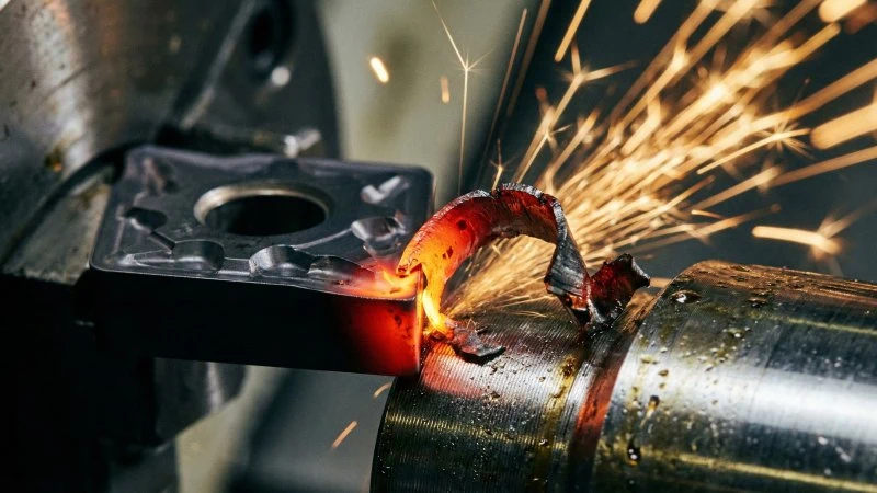
The challenge of controlling red-hot ribbon chips from hardened steel
When you turn soft steel, the material often breaks naturally because it is ductile and tears easily. Hard turning is different. When you machine hardened steel (typically 50–65 HRC), the process generates intense heat. This heat is actually necessary. It softens the metal slightly at the exact point of the cut, allowing the tool to shear it off.
However, this creates a unique problem for chip control. The chip comes off the part as a continuous, red-hot ribbon. Because the steel is hardened, this ribbon is incredibly strong and stiff.
On a traditional flat top insert, there is nothing to stop this ribbon. It slides straight across the top of the insert. It does not curl. It does not hit a wall. It simply grows longer and longer.
Key Differences in Chip Formation:
| Feature | Soft Turning (Standard Steel) | Hard Turning (Hardened Steel) |
|---|---|---|
| Chip Texture | Ductile, tears easily | Rigid, stiff, and strong |
| Temperature | Moderate | Extreme (Red-hot) |
| Behavior on Flat Top | May curl naturally or break | Flows straight like a wire |
This “red-hot wire” is dangerous. It does not act like a soft shaving. It acts like a hardened spring. Without a physical obstruction to force it to curl, it becomes a chaotic element in your machine.
Balancing the conflict between CBN brittleness and chipbreaker depth
You might wonder, why didn’t manufacturers always put chipbreakers on CBN inserts? The answer lies in the material properties of Polycrystalline Cubic Boron Nitride (PCBN)3.
PCBN is the second hardest material on earth, but it is also brittle. It behaves somewhat like a ceramic. To make a chipbreaker, you must remove material from the top of the insert to create a groove or a wall.
This creates a structural conflict:
- Deep Grooves: A deep groove effectively catches the chip and breaks it. However, it makes the cutting edge thin and weak.
- Shallow/Flat Tops: A flat top keeps the cutting edge thick and strong. However, it fails to control the chip.
In the past, manufacturers prioritized strength. They feared that adding a groove would cause the expensive CBN tip to snap under the high pressure of hard turning.
Think of it like a carbide end mill. If you grind the flutes too deep, the core of the tool becomes thin. When you apply cutting pressure, the tool snaps. Similarly, if a chipbreaker on a CBN insert is too aggressive, the cutting edge loses support. It may chip or crater prematurely.
Note: The structural integrity of specific chipbreaker designs varies significantly between manufacturers. The specific edge preparation (T-land)4 required to support a groove depth is a critical spec to review in technical catalogs.
Modern laser ablation technology now allows for precision grooves that balance this conflict. But traditional flat tops remain common simply because they offer the maximum possible edge strength, even if chip control is poor.
Safety risks posed by long chips in high-speed hard turning
The failure to break chips is not just a cosmetic issue; it is a major safety and productivity risk. Hard turning often happens at high surface speeds to generate the necessary heat for cutting.
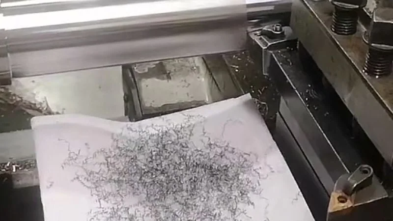
When a continuous chip forms at high speed, it creates a “bird nest.” This is a tangled ball of razor-sharp, hardened steel wire that wraps around the tool holder or the part itself.
The primary risks include:
- Operator Injury: Clearing a bird nest is hazardous. The chips are sharp enough to slice through gloves. If an operator tries to remove them while the spindle is winding down, the risk of severe injury is high.
- Automated Loader Jams: For mass production using auto-loaders or robots, bird nests are disastrous. The robot cannot grip the part if it is covered in steel wool. This triggers machine alarms and stops the entire production line.
- Surface Finish Damage: As the long chip whips around the rotating part, it can scratch the freshly machined surface. In precision bearing or shaft manufacturing, a single scratch means the part is scrap.
Using a flat top insert in these scenarios forces the operator to stop the machine frequently. They must open the door and manually pull chips away with a hook. This defeats the purpose of high-efficiency turning.
Matching PCBN Chipbreaker Geometries to Specific Applications
How do you determine which PCBN chipbreaker geometry is suitable for your specific hard turning operation?
To select the correct PCBN chipbreaker geometry, match the insert’s design to the depth of cut (DOC) and the severity of the interruption. Use “Fine” geometries for continuous finishing cuts with a DOC under 0.15mm to ensure chip engagement; choose “General” geometries for standard profiling and light interruptions; and apply “Heavy” geometries for removing carburized layers or interrupted cuts (DOC > 0.5mm), where edge strength is more critical than aggressive chip curling.
Fine breakers for continuous cuts and high surface finish requirements
When you manufacture high-precision components, such as bearing races or fuel injector pins, you typically remove very little material. The depth of cut (DOC) is often extremely shallow, sometimes less than 0.1mm.
In this scenario, a standard chipbreaker will fail. If the chipbreaker groove is located too far from the cutting edge, the thin chip will slide right over the groove without touching it. It effectively behaves like a flat top insert. To prevent this, “Fine” or “Finishing” breakers feature a very narrow “land” (the distance from the edge to the start of the groove).
Characteristics of Fine Geometries:
- Narrow T-land: Positioned close to the cutting edge to catch thin chips immediately.
- Sharp Cutting Action: Reduces cutting pressure to prevent workpiece deflection.
- Application Scope: Continuous cutting only; no interruptions.
Industry Example:
Consider an operator turning a hardened pin (60 HRC) with a stringent surface finish requirement of Ra 0.25. If they use a standard breaker, the low cutting pressure fails to curl the chip, resulting in a “bird nest” that scratches the surface. By switching to a Fine geometry, the chip hits the breaker wall immediately, curling tightly and falling away from the delicate surface.
Note: Different tool manufacturers define “Fine” and “Finishing” ranges differently. Always verify the specific minimum depth of cut recommended for the specific grade, as operating below this limit renders the chipbreaker useless.
General purpose breakers for standard hardened steel components
For the majority of hard turning jobs, you need a balance. You might be turning a transmission shaft that has a long continuous section but also a small oil hole or a keyway. A Fine breaker is too fragile for the oil hole, but a Heavy breaker is too blunt for the continuous section.
This is where “General Purpose” (often labeled as “Medium”) geometries excel. They are the versatile workhorses of the machine shop. They feature a slightly wider T-land than Fine breakers, giving the edge enough strength to survive minor interruptions while still providing excellent chip control at moderate depths of cut (typically 0.15mm to 0.35mm).
Why they are the default choice:
- Versatility: They handle both plain turning and slight profiling.
- Stability: The design balances cutting forces, reducing chatter during extended cuts.
- Chip Management: They effectively break chips into manageable “6” or “9” shapes rather than tight springs or long wires.
Think of this geometry like a standard CNMG carbide insert used for soft steel roughing—it isn’t specialized for the finest finish or the heaviest roughing, but it is the safest starting point for a new job. If you are setting up a new line for automotive gear shafts and are unsure of the exact variances in the casting or forging, a General Purpose geometry provides the necessary safety margin.
Heavy duty geometries for interrupted cuts and removing carburized layers
Some hard turning applications are brutal. You might need to machine the face of a gear that has interrupted teeth, or you might need to remove the “case” (the hardened outer layer) from a heat-treated bar.
In these situations, the cutting forces are violent. The tool exits and re-enters the cut repeatedly, subjecting the PCBN tip to massive impact shock. A Fine or General breaker would chip instantly under this load.
Heavy Duty geometries (often labeled “Roughing” or “Interrupted”) prioritize survival over neat chips. They feature a wide, negative T-land and a more open breaker groove. The goal here is not necessarily to curl the chip tightly, but to simply guide the heavy, thick chip away from the workpiece without collapsing the cutting edge.
Comparison of Application Scenarios:
| Application Feature | Recommended Geometry | Typical DOC Range | Primary Goal |
|---|---|---|---|
| Continuous / Precision | Fine / Finishing | 0.05mm – 0.15mm | Surface Finish (Ra) |
| Light Interruption | General Purpose | 0.15mm – 0.35mm | Process Stability |
| Heavy Interruption | Heavy Duty | 0.30mm – 0.60mm+ | Edge Security |
Real-world Scenario:
Imagine turning a hardened gear face with distinct teeth. As the tool passes over the gaps between teeth, it is essentially hammering the workpiece. This is mechanically similar to a milling operation, where the tool edge takes repeated impacts. A Heavy Duty PCBN geometry mimics a robust milling insert design—it uses a strong, reinforced edge to absorb the shock. If you used a Fine breaker here, the sharp edge would fracture on the first impact.
Optimizing Cutting Parameters for CBN Chip Control
How do cutting parameters significantly influence chip formation when turning hardened steel with CBN inserts?
To optimize chip control, the depth of cut (DOC) must be deep enough to bypass the edge preparation and engage the breaker groove, while the feed rate must be sufficient to force the chip to curl without overloading the brittle CBN tip. Furthermore, maintaining a high cutting speed6 is mandatory to generate the necessary shear zone heat, which softens the hardened steel chip and allows it to deform rather than remaining stiff and wire-like.
Adjusting depth of cut to engage the chipbreaker geometry effectively
Many operators fail to break chips because they treat a chipbreaker insert exactly like a flat top insert. They often set a very light depth of cut (DOC) to “sneak up” on a final dimension. However, on a 3D chipbreaker insert, this strategy frequently fails.
For a chipbreaker to work, the material must physically hit the geometry. PCBN inserts almost always feature a “T-land” or “Chamfer” on the cutting edge to protect it from chipping. This chamfer is a small negative angle ground onto the very edge.
If your depth of cut is smaller than the width of this chamfer, you are not actually cutting with the sharp chipbreaker groove. You are cutting solely on the negative land.
The Rule of Engagement:
- Shallow Cut: If the DOC is less than the T-land width, the chip flows over the land and misses the breaker groove entirely. This results in long, straight stringers.
- Correct Cut: The DOC should typically be larger than the T-land width. This ensures the chip flows over the land and crashes into the back wall of the chipbreaker, forcing it to curl.
Note: T-land specifications vary significantly by manufacturer and grade. A standard heavy-coated CBN grade might have a 0.15mm T-land, while a light finishing grade might have a 0.05mm T-land.
Setting the feed rate to force chip curling without fracturing the CBN edge
Once the depth of cut is set correctly, the feed rate becomes the steering wheel for the chip. The feed rate determines the thickness of the chip. A chip that is too thin will be flexible and wiry, allowing it to bypass the breaker. A chip that is thicker will be stiffer and more likely to break when it hits the geometry.
However, you must be careful. PCBN is brittle. If you increase the feed rate too much, you increase the cutting pressure. Unlike carbide, which might deform under pressure, CBN will fracture.
Finding the Feed Rate Sweet Spot:
- Too Low (e.g., < 0.05 mm/rev): The chip is like a thin foil. It is too weak to be guided by the chipbreaker. It usually creates a “bird nest” around the part.
- Optimal Range (e.g., 0.08 – 0.15 mm/rev): The chip has enough body to be pushed against the breaker wall. The mechanical force curls the chip into a “6” or “9” shape.
- Too High (e.g., > 0.25 mm/rev): The chip is controlled, but the pressure on the cutting edge exceeds the transverse rupture strength of the CBN. This leads to catastrophic edge failure.
This mechanism is similar to a CNC wire forming machine. If the wire (chip) feed is too slow or the wire is too thin, it lacks the column strength to bend against the tooling dies; it simply buckles. You need sufficient material thickness (feed rate) to give the chip the structural integrity to be forced into a curl by the chipbreaker wall.
The critical role of cutting speed in generating heat to soften the chip
This is the most counter-intuitive part of hard turning for machinists used to standard steel. In standard turning, slowing down usually helps fix problems. In hard turning with CBN, slowing down often causes chip control failure.
Hardened steel (HRC 50-65) is brittle and strong at room temperature. To form a chip, you need to soften the metal right at the cutting point. We call this “plasticization.”
How Speed Creates Control:
- High Speed = Heat: High surface speed (Vc) generates intense friction heat in the shear zone.
- Heat = Softness: This heat momentarily drops the hardness of the chip. A chip that is effectively “softer” is much easier to curl.
- Low Speed = Stiffness: If you run too slow, the chip remains cold and hard. A cold, hardened chip acts like a spring. It refuses to curl and fights against the chipbreaker, often causing vibration or straight chips.
Therefore, if you are experiencing long, stringy chips, the solution is often to increase the RPM, not decrease it.
Parameter Interaction Matrix:
| Parameter | Adjustment | Effect on Chip | Risk if Over-adjusted |
|---|---|---|---|
| Depth of Cut (ap) | Increase | Engages breaker geometry | Vibration / Chatter |
| Feed Rate (fn) | Increase | Forces chip against wall | Edge Fracture |
| Speed (Vc) | Increase | Softens chip (Plasticization) | Rapid Flank Wear |


Troubleshooting Chip Issues Specific to Hardened Steel
How do you diagnose and resolve frequent chip control failures that occur specifically during the turning of hardened steel components?
To troubleshoot chip issues in hard turning, first identify the specific failure mode: “bird nesting” typically indicates a depth of cut that is too shallow to engage the breaker; edge chipping suggests the chipbreaker geometry is too aggressive for the feed rate; and surface finish degradation usually means chips are curling back onto the workpiece (chip hammering). Corrective actions involve adjusting the cut depth relative to the nose radius, switching to a more open breaker geometry, or altering the chip flow direction.
Solving bird nesting issues when turning case-hardened shafts
Bird nesting is the most common frustration in hard turning. It occurs when long, stringy chips wrap around the tool or part. This is particularly problematic when turning case-hardened shafts (e.g., automotive transmission shafts).
In case-hardened parts, the hardness is not consistent throughout. The outer layer is hard (60 HRC), but the material gets softer as you cut deeper. If your depth of cut varies, or if the part has significant runout, the tool might dip into softer material.
The “Soft Zone” Problem:
CBN inserts are designed for hard materials. If the tool encounters the softer “transition zone” (below 50 HRC) of a case-hardened shaft, the chip stops breaking. Soft steel is gummy. It does not fracture like brittle hardened steel. It flows like taffy, bypassing the chipbreaker geometry designed for hard chips.
Troubleshooting Steps:
- Check the Depth: Ensure your depth of cut stays strictly within the hardened “case” layer. If you must cut into the soft core, you may need to switch to a carbide insert for that specific pass.
- Increase Feed Rate: If you are safely in the hard zone but still getting nests, the chip is too thin. Increase the feed rate slightly (e.g., by 10-15%). This makes the chip stiffer, forcing it to snap when it hits the breaker wall.
- Verify Nose Radius Engagement: A common mistake is using a large nose radius (e.g., 0.8mm or 1.2mm) with a light depth of cut (e.g., 0.1mm). In this scenario, the chip forms along the radius, effectively thinning the chip. You must either increase the depth of cut or switch to a smaller nose radius (e.g., 0.4mm) to create a thicker chip that the breaker can control.
Identifying edge chipping caused by aggressive chipbreaker designs
Sometimes, the chip breaks too well. You might hear a “clicking” sound during the cut, or notice that tool life has dropped dramatically. Upon inspection, the cutting edge looks jagged rather than worn.
This is often caused by a chipbreaker that is too aggressive.
In hard turning, the chip is a rigid, high-strength ribbon. If the chipbreaker wall is too steep or positioned too close to the cutting edge, the chip crashes into it with immense force. Because CBN is brittle, this impact transmits shock back into the cutting edge, causing it to fracture (chip).
Analogy: The Mechanical Shock Effect
Using an aggressive, steep chipbreaker on hardened steel is mechanically similar to performing a heavy interrupted milling cut with a positive rake insert.
- Open Geometry: Acts like a reinforced, negative rake edge that absorbs the pressure gradually.
- Aggressive Geometry: Acts like a sharp positive edge taking a heavy impact. The sudden force of the rigid chip hitting the steep wall creates a shock load that exceeds the transverse rupture strength of the CBN tip.
- The Result: The insert doesn’t wear out; it snaps.
Differentiation Table: Wear vs. Chipping
| Symptom | Appearance | Probable Cause | Corrective Action |
|---|---|---|---|
| Normal Flank Wear | Smooth, uniform abrasion on the side | Chemical/Abrasive wear | Maintain current parameters |
| Crater Wear | A smooth hollow on the top face | Heat/Chip friction | Use a harder grade or reduce speed |
| Edge Chipping | Jagged, irregular fractures on the edge | Aggressive Breaker / Mechanical Shock | Switch to a “Heavy” or “Open” geometry |
Note: Visual inspection of CBN failure modes can be difficult without magnification. A 10x loupe is recommended to distinguish between crater wear (which is normal) and micro-chipping (which requires a geometry change).
Correcting surface finish degradation due to chip re-cutting
You may encounter a situation where the chip control seems perfect—short, broken chips are flying everywhere—but the surface finish (Ra) of the part is poor. The surface might look cloudy or have random scratches.
This is often caused by “Chip Hammering” or “Re-cutting.”
This happens when the chipbreaker curls the chip too tightly. Instead of ejecting the chip away from the cutting zone, the chip curls into a tight circle and hits the workpiece surface or gets trapped between the tool and the part.
How to Fix Flow Direction:
- Change the Approach Angle: The lead angle of the tool holder dictates where the chip goes. If you are using a standard CNMG style holder (negative lead), the chip might be pushed toward the finished surface. Changing to a holder with a different approach angle can direct the chip away from the part.
- Loosen the Chipbreaker: If chips are curling into tiny, tight springs that scratch the part, the breaker is too tight. Switch to a geometry with a wider T-land or a more open groove. This will produce a slightly more open chip (a “6” shape rather than a “9” shape) that clears the cutting zone more easily.
- Air Blast Positioning: Hard turning is typically performed dry (without coolant) to avoid thermal shock to the CBN. However, a strategically aimed air nozzle is crucial. Ensure the air blast is pushing chips away from the finished diameter, not just blowing them randomly around the machine.
Conclusion
Selecting the right CBN chipbreaker is not just about convenience; it is about process security. By understanding the interaction between your specific application (continuous vs. interrupted), the chipbreaker geometry, and your cutting parameters, you can eliminate the hazards of bird nesting. Remember to start with a General purpose breaker, ensure your depth of cut exceeds the T-land, and maintain high speeds to soften the chip. Mastering these elements transforms hard turning from a chaotic struggle into a reliable, high-precision process.
Ready to Optimize Your Hard Turning Process?
Don’t let bird nesting and unpredictable tool life slow down your production. Whether you need help selecting the right chipbreaker geometry or optimizing cutting parameters, our engineering team is here to assist. Contact us today for a custom solution that fits your specific machining needs.
References
- CBN Chipbreaker Inserts1 – ZYDiamondTools product page detailing the specifications and options for CBN inserts with chipbreakers.
- Hard Turning2 – ZYDiamondTools blog post explaining the process of hard turning and comparing it to grinding.
- Polycrystalline Cubic Boron Nitride (PCBN)3 – Wikipedia entry providing the chemical and physical properties of PCBN material.
- Edge Preparation (T-land)4 – ZYDiamondTools guide on edge radiusing and chamfering for insert protection.
- Ra 0.25 – Wikipedia article explaining surface roughness parameters like Ra.
- Cutting Speed6 – ZYDiamondTools calculator for determining optimal speeds and feeds for machining.


