-
Whatsapp: +86 13526572721
-
Email: info@zydiamondtools.com
-
Address: AUX Industrial Park, Zhengzhou City, Henan Province, China
-
Whatsapp: +86 13526572721
-
Email: info@zydiamondtools.com
-
Address: AUX Industrial Park, Zhengzhou City, Henan Province, China

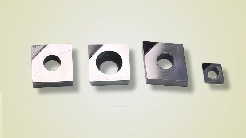
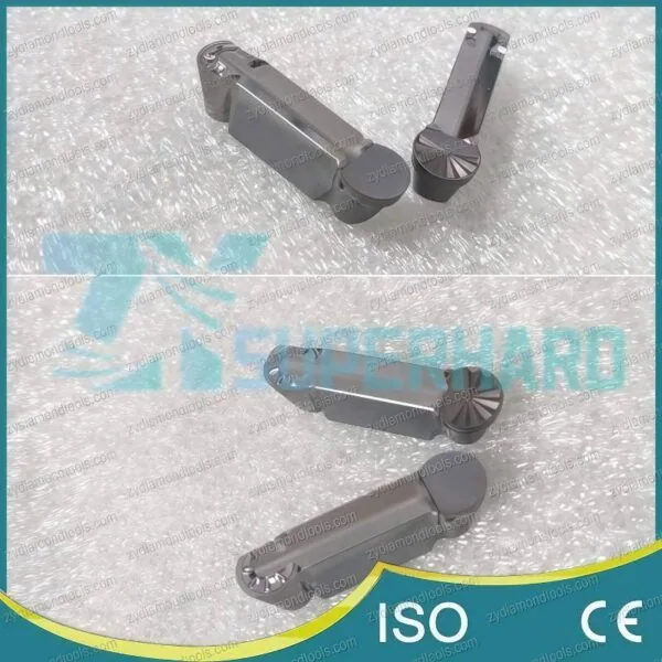
Why and How Should You Use Edge Radiusing on PCD Inserts for Optimal Machining?
So, why is edge radiusing on PCD inserts so important for machining, and how should you approach using it effectively?
Edge radiusing is crucial for PCD inserts primarily because it strengthens the inherently brittle cutting edge, removes microscopic manufacturing defects, and consequently improves tool life, workpiece surface finish, and overall process stability significantly. Effectively using edge radiusing involves understanding the trade-offs between edge strength and sharpness, selecting the appropriate radius size based on the specific machining operation and workpiece material, knowing how the radius is technically applied (like grinding, laser processing, or honing), and clearly specifying your requirements when sourcing appropriately prepared tools or edge preparation services.
Why is Specific Edge Preparation Critical for PCD Material?
So, why exactly is specific edge preparation such a critical step when working with PCD tooling material?
Specific edge preparation is vital for PCD (Polycrystalline Diamond1) material primarily because, despite its exceptional hardness and resistance to wear, PCD is inherently brittle on a microscopic scale. Additionally, manufacturing processes like grinding or sintering can introduce tiny, often invisible, defects along the cutting edge. Carefully preparing the edge, for instance through radiusing or honing, effectively removes these flaws and modifies the edge geometry to better distribute stress, thereby significantly strengthening it against premature chipping or catastrophic fracture during machining.
Understanding the Brittleness Behind PCD Hardness
Polycrystalline Diamond, or PCD, is famous for being incredibly hard. Think of it as one of the toughest materials available for cutting tools, second only to natural diamond itself. While this hardness provides excellent wear resistance, especially when cutting abrasive materials like high-silicon aluminum or carbon fiber composites, it also means the material can be brittle2 at the microscopic cutting edge.
What does brittleness mean here? It means that despite resisting scratches and wear very well, the material can fracture easily if subjected to sharp impacts or high stress concentrations. A theoretically perfect, sharp edge on a PCD insert, while appealing for initial sharpness, lacks the toughness to consistently withstand the cutting forces and impacts encountered during machining. Without proper support or modification through edge preparation, that ultra-hard edge can easily chip. Therefore, managing this inherent brittleness is a key reason why edge preparation is not just beneficial, but often necessary for reliable performance.
The Need to Remove Microscopic Edge Defects
Even with the most advanced manufacturing techniques, creating a “perfect” cutting edge on PCD is incredibly challenging. The processes used, such as sintering the diamond particles together with a binder or grinding the insert to its final shape3, can leave behind tiny imperfections. These aren’t usually visible to the naked eye but can include:
- Micro-cracks: Tiny fissures originating from the grinding process or internal stresses.
- Uneven Edge Line: The edge might not be perfectly straight or smooth at a microscopic level.
- Loose Diamond Grains: Some diamond particles might not be fully secured within the binder matrix right at the edge.
- Binder Pooling: Small areas where the metallic binder material might concentrate near the edge.
Why do these tiny flaws matter so much? Think of them as starting points for failure. Under the intense pressure and heat of cutting, these microscopic defects act as stress concentrators. This means the cutting forces, instead of spreading out evenly, focus intensely on these weak points. Consequently, a small defect can quickly grow into a larger chip or even lead to the edge fracturing much earlier than expected. As industry sources like BIG DAISHOWA and Conicity Technologies have noted, such defects are present on nearly all tools before edge preparation, and removing them is crucial for achieving consistent, high-level performance. Addressing these initial flaws through edge preparation is fundamental to unlocking the full potential and lifespan of PCD tooling.
Strengthening the Edge to Prevent Chipping Failure
Edge preparation does more than just remove defects; it actively strengthens the cutting edge by changing its micro-geometry. Creating a controlled radius or a small flat land (hone) along the edge modifies how forces are distributed.
This change in geometry distributes stress over a wider area, much like how a rounded corner on a load-bearing structure is more resistant to stress concentration than a sharp angle. The key benefits of this geometric strengthening include:
- Stress Distribution: By replacing the extremely fine, sharp edge with a small, precisely controlled radius, the cutting forces are spread over a larger area. This significantly lowers the stress concentration right at the cutting tip.
- Increased Edge Toughness: This change in geometry effectively makes the edge tougher and more resistant to the impacts encountered, especially during interrupted cuts (like milling) or when machining materials with hard inclusions.
- Reduced Chipping: The direct result is a substantial reduction in the tendency for the edge to micro-chip or fracture prematurely. This leads to more predictable tool behavior and a longer, more reliable tool life.
Essentially, edge preparation transforms a potentially fragile, ultra-sharp edge into a robust, still sharp, but significantly more durable cutting interface. The specific geometry (like the exact radius size) is often carefully chosen based on the PCD grade, the material being machined, and the type of operation, ensuring the optimal balance between sharpness and strength for the task at hand.
Common edge preparation methods include radiusing, chamfering (often referred to as T-lands or K-lands), and combined forms. Edge radiusing is one widely used form among these, and this article will now focus in detail on edge radiusing.

What Key Performance Gains Does Edge Radiusing Deliver?
So, what are the main performance advantages you actually gain by applying edge radiusing to PCD inserts?
Applying edge radiusing to PCD inserts delivers several key performance gains, primarily including significantly extended tool life through enhanced wear resistance and reduced chipping. Additionally, it often leads to improved workpiece surface finish, lower cutting forces and less heat generation during the cut, and contributes to overall greater process predictability and stability in demanding machining operations.
Significantly Extending Tool Life and Wear Resistance
One of the most impactful benefits of edge radiusing is a noticeable increase in tool life. As we discussed earlier, PCD’s inherent brittleness makes sharp, unprepared edges prone to micro-chipping. By creating a small radius, the edge becomes significantly stronger and more resistant to these small fractures, which are often the primary cause of premature tool failure.
Furthermore, the radiused edge tends to wear more predictably through abrasion rather than sudden chipping. This allows the PCD insert to withstand the rigors of cutting abrasive materials, like high-silicon aluminum found in engine blocks or composites used in aircraft structures, for much longer periods.
- How it helps: A stronger, more chip-resistant edge simply lasts longer.
- The result: This translates directly into cost savings4 through fewer tool changes, reduced machine downtime, and less operator intervention. While the exact increase in tool life can vary significantly based on the specific PCD grade, workpiece material, cutting parameters, and the radius applied, industry experience and some studies (like those reported for similar PCBN materials showing potential increases of 30% or more, though specific results for PCD should be verified for your application) indicate substantial improvements are often achievable. Always consult with your tooling supplier to understand the expected gains for your particular setup.
Dramatically Improving Workpiece Surface Finish (Ra)
You might think the sharpest possible edge gives the best surface finish. While a perfectly sharp edge can produce a very fine finish initially, maintaining that perfect edge on PCD is difficult due to its brittleness. A carefully radiused edge offers a more stable and consistent cutting action over a longer period.
Here’s how it works:
- Edge Stability: The strengthened, radiused edge resists micro-chipping. A chipped edge inevitably leaves imperfections on the workpiece surface. By preventing chipping, the radiused edge maintains its integrity longer, leading to a consistently smoother finish.
- Reduced Built-Up Edge (BUE): In some non-ferrous materials like aluminum, material can stick (weld) to the cutting edge, known as Built-Up Edge (BUE)5. A smooth, radiused edge can sometimes reduce the tendency for BUE to form compared to a rapidly wearing sharp edge, further contributing to a better finish.
This results in achieving and maintaining lower surface roughness (Ra)6 values, which is critical for components requiring high precision and smooth surfaces, such as hydraulic valve bodies or aerospace components. However, it’s important to note there’s a balance; an excessively large radius can actually increase cutting forces and potentially degrade the finish. The optimal radius depends on the finishing requirements and material. Remember that achievable Ra values are highly dependent on the entire machining system (machine rigidity, spindle quality, feed rates) not just the tool edge prep, so verify expectations with your supplier.
Reducing Cutting Forces, Heat, and Machine Load
Edge preparation, specifically radiusing, can also positively influence the forces and heat generated during cutting. While a perfectly sharp edge has the lowest initial force, as soon as micro-wear or chipping occurs, forces can increase unpredictably. A stable, radiused edge often leads to more consistent forces throughout its usable life.
- Smoother Interaction: The rounded geometry can promote a smoother shearing action as it interacts with the workpiece material, potentially reducing friction compared to a jagged, chipped edge or even a theoretically perfect but extremely thin edge prone to deflection.
- Lower Heat: Reduced friction naturally leads to less heat being generated in the cutting zone. This is beneficial for both the tool (reducing thermal wear) and the workpiece (preventing thermal damage or distortion).
- Reduced Load: Lower and more consistent cutting forces mean less load on the machine tool’s spindle and feed drives, contributing to better overall machine health and potentially allowing for more aggressive (faster) cutting parameters within the machine’s limits. Studies on related materials like PCBN have sometimes shown force and heat reductions (e.g., 10-15%), but the effect for PCD is highly application-specific and should be evaluated case-by-case.
Enhancing Predictability and Process Stability
Perhaps one of the most crucial gains, especially in modern manufacturing environments, is increased process predictability and stability. Unpredictable tool failure is a major disruptor, leading to scrap parts, machine downtime, and potential damage.
By strengthening the edge and promoting more gradual wear rather than sudden fracture, edge radiusing makes the tool’s behavior far more consistent.
- Reliable Performance: Knowing that an edge is less likely to chip unexpectedly allows for greater confidence in the machining process, particularly in automated or unattended operations (“lights-out” manufacturing).
- Consistent Quality: Stable tool wear ensures that part dimensions and surface finish remain within tolerance for a longer production run, leading to less variation between parts and reduced scrap rates.
- Easier Process Control: A predictable tool life allows for planned tool changes rather than reactive replacements, simplifying production scheduling and maintenance.
Ultimately, edge radiusing transforms the PCD insert from a potentially high-performing but somewhat fragile tool into a consistently reliable and durable production asset.

How is the Radius Technically Applied to PCD Edges?
Okay, so how is that important radius actually created on the cutting edge of a PCD insert?
Creating a precise radius on a PCD insert edge typically involves highly controlled processes such as precision grinding using specialized diamond wheels, non-contact laser ablation which utilizes focused energy beams to remove material, or advanced honing techniques employing abrasive filaments or pastes. Each of these methods carefully shapes the desired edge micro-geometry by removing microscopic amounts of the ultra-hard PCD material.
Controlled Abrasive Methods: Precision Grinding
One common and well-established method for creating an edge radius on PCD is precision grinding. Because PCD is extremely hard, this process requires specialized equipment and materials.
- The Process: A very fine, rotating grinding wheel, typically made with diamond abrasive particles embedded in a suitable bond, is carefully brought into contact with the PCD insert’s edge. The machine precisely controls the position of the insert relative to the wheel, the pressure applied, and the rotational speeds.
- Forming the Radius: The radius is generated either by the profile dressed onto the grinding wheel itself or by the programmed path the insert follows relative to the wheel. The grinding action meticulously removes tiny amounts of PCD material, sculpting the sharp corner into a smooth, rounded edge.
- Key Factors: Achieving a consistent and accurate radius through grinding depends heavily on several factors. These include the diamond grit size and concentration in the wheel, the type of bond holding the diamonds, the stability and accuracy of the grinding machine, and minimizing wheel runout. It’s crucial to remember that the optimal grinding parameters can vary significantly depending on the specific PCD grade and the desired radius size; consulting with equipment or tooling suppliers for recommended settings is always advisable.
Non-Contact Methods: Laser Processing Advantages
Another advanced technique for edge radiusing is laser processing or laser ablation. This method offers distinct advantages, particularly due to its non-contact nature.
- The Process: In this method, a highly focused laser beam is directed at the edge of the PCD insert. The intense energy from the laser heats the material at the focal point extremely rapidly, causing tiny amounts of the PCD and binder material to melt and vaporize. By precisely controlling the laser’s power, pulse duration, frequency, and movement path, material can be selectively removed to form a specific edge radius.
- Key Advantage: Non-Contact: A major benefit here is that there is no direct physical tool pressure applied to the PCD edge during processing. This minimizes the risk of inducing mechanical stress or micro-cracks, which can be a concern with grinding extremely brittle materials. As reported in industry findings, this can lead to very smooth edge finishes and potentially less sub-surface damage.
- Precision and Control: Laser systems offer very high precision, capable of creating very small and consistent edge radii. The final edge quality, however, depends greatly on optimizing laser parameters like power density, pulse characteristics, scanning speed, and potentially the use of assist gases. As with grinding, the ideal laser settings are specific to the PCD material and desired outcome, requiring careful setup and verification, often based on supplier recommendations.
Finishing Methods: Advanced Honing Techniques
Honing techniques represent another category of methods used for edge preparation, often focused on producing very smooth, consistent radii and removing any minor inconsistencies left by initial grinding.
- Focus on Brush Honing: A prominent method is brush honing (sometimes called flexible honing or brushing). This typically involves using rotating brushes made with durable yet flexible filaments, such as nylon, impregnated with fine abrasive particles (often diamond). These flexible filaments conform to the shape of the cutting edge as the brush rotates against it. This action gently abrades the edge, removing microscopic peaks, smoothing the transition, and creating a well-blended radius. The process is controllable through factors like brush type, abrasive grit size, rotational speed, and applied pressure.
- Other Honing Approaches: While brush honing is common for controlled radiusing, other mass finishing techniques like vibratory honing or slurry honing might also be used in some edge preparation scenarios, although perhaps offering less precise control over the specific radius size compared to brushing or laser methods.
- Goal: The primary goal of these honing techniques in edge radiusing is typically to achieve a very high level of edge smoothness and consistency, ensuring uniform performance. The effectiveness and resulting edge quality depend on selecting the correct honing media (brush type, abrasive), process time, and machine parameters. Tool manufacturers often have specific, optimized honing processes tailored to their PCD grades and tool geometries, so verifying details with them is recommended.
How Do You Choose the Correct Edge Radius for Your Application?
Choosing the right edge radius seems important, so how do you actually select the correct one for your specific PCD application?
Selecting the correct edge radius for a PCD insert involves carefully balancing the trade-off between edge strength, which generally favors larger radii, and cutting edge sharpness, which favors smaller radii. Key decision factors include the type of machining operation (roughing typically uses larger radii for durability, while finishing often uses smaller radii for precision), the specific workpiece material being machined (more abrasive materials may require larger radii), and the required surface finish quality.
The Trade-off: Edge Strength vs. Cutting Edge Sharpness
Choosing an edge radius for PCD inserts is fundamentally about finding the right balance. There’s a direct trade-off between making the edge stronger and keeping it as sharp as possible.
- Larger Radius: A larger radius significantly increases the strength of the cutting edge. As discussed earlier, this makes it much more resistant to chipping and breakage, especially under heavy loads or during interrupted cuts. Consequently, it generally leads to longer tool life. However, a larger radius also means the edge is technically less sharp, which can sometimes increase cutting forces and might slightly impact the achievable surface finish in very fine cutting operations.
- Smaller Radius: A smaller radius results in a sharper cutting edge. This can lead to lower cutting forces, particularly during initial engagement, and potentially allows for achieving finer surface finishes, especially when machining softer non-ferrous materials or requiring very precise cuts. The downside? This sharper edge is inherently weaker and more susceptible to micro-chipping or rapid wear, especially in demanding applications or abrasive materials, often resulting in shorter overall tool life.
Understanding this core trade-off is the first step in making an informed decision for your specific needs. Which is more critical for your operation: maximum durability or ultimate sharpness and finish?
Selecting Radius Based on Operation: Roughing vs. Finishing
The type of machining operation plays a major role in determining the appropriate edge radius. The goals for roughing are very different from the goals for finishing.
- Roughing Operations: The main aim here is usually high material removal rate (MRR) and tool durability. The tool needs to withstand significant cutting forces, potential interruptions in the cut (like in milling), and variations in material stock. Therefore, for roughing, a larger edge radius is typically preferred to maximize edge strength and prevent premature failure.
- Finishing Operations: In finishing, the priorities shift to achieving excellent surface quality (low Ra value) and tight dimensional accuracy. While durability is still important, edge sharpness becomes more critical for producing a clean cut with minimal material deformation. Consequently, a smaller edge radius is often chosen for finishing passes to ensure the sharpest possible cutting action and potentially lower cutting forces, which helps minimize tool deflection and improve accuracy.
Here’s a simple summary:
| Operation Type | Primary Goal | Typical Radius Choice | Key Reason |
|---|---|---|---|
| Roughing | Durability, MRR | Larger | Maximizes edge strength, withstands higher impact |
| Finishing | Surface Finish, Accuracy | Smaller | Provides sharper cut, potentially lower cutting forces |
Adapting Radius for Specific Materials (Alloys, Composites)
The material you are machining is another critical factor influencing the ideal edge radius. Different materials interact with the cutting edge in unique ways.
- Abrasive Materials: Materials like high-silicon aluminum alloys7 (often found in automotive engine parts, typically >12% Si), Metal Matrix Composites (MMC), Carbon Fiber Reinforced Polymers (CFRP)8, and Glass Fiber Reinforced Polymers (GFRP) are highly abrasive. They act like sandpaper on the cutting edge. For these materials, a larger edge radius is generally recommended. The increased strength helps resist the intense abrasive wear and prevents the edge from breaking down quickly. In composites, it also helps minimize issues like delamination or fiber pull-out.
- Less Abrasive / Softer Non-Ferrous Materials: Materials such as lower-silicon aluminum alloys (common in aerospace or consumer electronics), copper, brass, or certain plastics are less demanding on the cutting edge. For these materials, especially in finishing operations requiring a very smooth surface, a smaller edge radius can often be used effectively. The sharpness helps achieve a clean shear without needing the extreme edge strength required for highly abrasive materials.
Therefore, always consider the specific properties of your workpiece material when deciding on the edge preparation.
Typical Radius Values and Tolerances in Practice
While the optimal radius is always application-specific, general industry practice provides some starting points. It’s common to see edge radii specified in micrometers (µm).
- Example Ranges (Use with Caution):
- Finishing operations might utilize radii in the range of approximately 5 µm to 15 µm.
- General purpose or light roughing might use radii from 15 µm to 30 µm.
- Heavy roughing or machining very abrasive materials could potentially require radii larger than 30 µm.
Crucially, these are only general examples. The ideal value depends heavily on the specific PCD grade (finer grain PCD might support a sharper edge than coarser grain), the tool geometry, the machine tool’s condition, cutting parameters (speed, feed, depth of cut), and the factors discussed above (operation, material).
Tolerance (how much the actual radius can vary from the specified value) is also important for consistent performance. Tighter tolerances generally lead to more predictable results but may increase tool cost.
Always consult your tooling supplier’s catalogs or technical documentation for their specific recommendations. They have detailed knowledge of their PCD grades and edge preparation capabilities and can provide the best guidance for your application. Do not rely solely on general ranges; verify the optimal specifications for your unique machining scenario.

Where Can You Source Radiused PCD Inserts or Edge Prep Services?
Now that you understand why and how to choose an edge radius, where can you actually get these radiused PCD inserts or related services?
You can source PCD inserts with specific edge radii primarily from established cutting tool manufacturers, many of whom offer various edge preparations as standard catalog items or custom options. Alternatively, specialized companies focus specifically on providing edge preparation services, and they can often apply custom radii to inserts you provide or potentially source.
Identifying Tool Manufacturers with Edge Preparation Options
Many of the well-known global cutting tool manufacturers, as well as companies specializing in PCD and PCBN tooling, offer inserts with pre-applied edge preparations, including specific radii.
- Check Catalogs and Websites: The first step is often to consult the product catalogs or websites of major tool suppliers. Look for their PCD turning or milling insert sections. They frequently use specific codes or designations to indicate the type of edge preparation (e.g., ‘R’ for radius followed by a size, ‘H’ for honed, ‘T’ for T-land/K-land). Standard offerings might include common radius sizes.
- Contact Technical Support: If standard options don’t meet your needs, contacting the manufacturer’s technical support or sales representatives is highly recommended. They can advise on custom edge preparation possibilities for their PCD grades. Many manufacturers have in-house capabilities to apply specific radii upon request.For example, our company, ZYDiamondTools, can provide expert consultation and create tailored edge preparations for your specific PCD inserts.
- Integrated Expertise: A key advantage of sourcing directly from the tool manufacturer is their deep understanding of how specific edge preparations interact with their particular PCD grades and insert geometries. They can often provide valuable guidance on the best combination for your application.
Finding Specialized Edge Radiusing Service Providers
Besides tool manufacturers, there are companies whose core business is providing cutting tool modification and preparation services.
- Focused Expertise: These service providers specialize in processes like grinding, honing, or laser edge preparation. They may offer more flexibility for highly custom radii, small batch sizes, or applying edge preps to tools from various manufacturers. Companies noted for their specialized honing or laser systems fall into this category.
- Working with Existing Tools: Often, you can send your existing standard sharp-edged PCD inserts to these providers to have a specific radius applied. This can be a cost-effective option if you already have suitable inserts.
- How to Find Them: Searching online for terms like “cutting tool edge preparation services,” “tool honing services,” or “laser edge preparation” can help locate these specialized providers. Look for companies with specific experience handling ultra-hard materials like PCD.
Important Considerations When Specifying Edge Radius Requirements
Whether dealing with a tool manufacturer or a specialized service provider, clear communication of your requirements is essential to get the right edge preparation. Misunderstandings can lead to tools that don’t perform as expected.
Be prepared to provide the following details:
- Desired Radius Size: Clearly state the target edge radius value in micrometers (µm).
- Required Tolerance: Specify the acceptable deviation from the target radius (e.g., ±3 µm). Tighter tolerances ensure greater consistency but might increase cost or lead time. Discuss what tolerance is realistically achievable and necessary for your process.
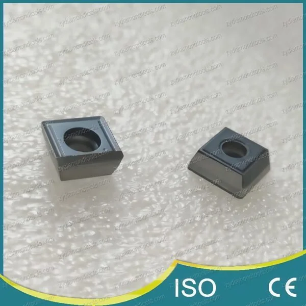
- PCD Insert Information: Provide the full designation of the insert (e.g., the ISO code like CNMG 120408). If you know the specific PCD grade, include that too. If not, describe the intended use.
- Application Context: Briefly explain the machining operation (e.g., finishing aluminum engine pistons), the exact workpiece material (e.g., AlSi17 alloy), and any critical performance goals (e.g., achieve Ra < 0.4 µm).
- Quantity: State the number of inserts requiring this specific edge preparation.
Remember to ask the supplier about their capabilities. Standard radius offerings, achievable tolerances, measurement methods, and lead times can vary significantly between companies. Discussing your needs upfront ensures you receive PCD inserts with an edge radius truly optimized for your application.
Conclusion
In summary, edge radiusing isn’t just an optional add-on for PCD inserts; it’s a critical aspect of leveraging their full potential in demanding machining applications. By addressing PCD’s inherent brittleness and removing microscopic flaws, a well-chosen edge radius significantly boosts tool life, improves surface finish, and enhances overall process reliability.
While selecting the correct radius requires careful consideration of the specific operation, workpiece material, and performance goals, understanding the fundamental trade-offs and knowing how these radii are applied provides a solid foundation for making informed decisions. Whether sourcing inserts with standard edge preps from tool manufacturers or utilizing specialized service providers for custom requirements, clear communication of your needs is paramount. Taking the time to optimize the edge preparation is a key step towards achieving consistent, high-quality results and maximizing the value of your PCD tooling investment.
References
- Polycrystalline Diamond1 – ZYDiamondTools overview explaining what PCD tools are.
- brittle2 – Wikipedia article defining brittleness in materials science.
- grinding the insert to its final shape3 – ZYDiamondTools article discussing sharpening techniques for PCD/PCBN tools, related to shaping edges.
- cost savings4 – ZYDiamondTools guide explaining Total Cost of Ownership (TCO) for superhard tooling.
- Built-Up Edge (BUE)5 – Wikipedia article defining Built-Up Edge in the context of machining.
- surface roughness (Ra)6 – Wikipedia article explaining surface roughness, including the Ra parameter.
- high-silicon aluminum alloys7 – A ZYDiamondTools guide to solving the challenges of machining high-silicon aluminum with PCD tooling, featuring real-world case studies.
- Carbon Fiber Reinforced Polymers (CFRP)8 – ZYDiamondTools article exploring PCD tooling for aerospace composites like CFRP.


