-
Whatsapp: +86 13526572721
-
Email: info@zydiamondtools.com
-
Address: AUX Industrial Park, Zhengzhou City, Henan Province, China
-
Whatsapp: +86 13526572721
-
Email: info@zydiamondtools.com
-
Address: AUX Industrial Park, Zhengzhou City, Henan Province, China

Turning Clutch Pressure Plates with PCBN Inserts: Optimization & Troubleshooting
What are the key strategies for machining gray cast iron clutch pressure plates using PCBN inserts?
Optimizing this process requires selecting high-content Solid CBN inserts with negative T-land edge preparation to withstand abrasive inclusions and interrupted cuts. Furthermore, operators must utilize dry machining protocols with surface speeds between 500–800 m/min to manage heat generation, while employing full-grip pie jaws to eliminate vibration and ensure dimensional stability.
Critical PCBN Grade and Edge Preparation Strategies for Gray Cast Iron
What is the most effective PCBN insert specification for turning gray cast iron clutch pressure plates?
The optimal strategy requires selecting a Solid CBN grade with high CBN content (approx. 85-90%) and a ceramic binder to withstand abrasive wear from casting skin and sand inclusions. Furthermore, engineers must apply a specific negative T-land (chamfer) to the cutting edge to protect against chipping during interrupted cuts, while utilizing Wiper geometry to maintain surface finish requirements even at accelerated feed rates.
Determining optimal CBN content for abrasive resistance against sand inclusions
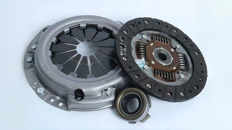
Clutch pressure plates are typically manufactured from HT200 or HT250 gray cast iron1. While this material is excellent for friction, the casting process often leaves behind a hard surface “skin” and microscopic sand inclusions. These impurities act like grinding grit against the cutting tool. Therefore, selecting the right Polycrystalline Cubic Boron Nitride (PCBN) content is the first line of defense.
For this application, Solid CBN inserts2 are generally superior to brazed tipped inserts. This is because Solid CBN offers higher thermal stability and allows for the use of multiple cutting corners.
When choosing the grade, you must prioritize High CBN Content. A grade with 85% to 90% CBN particles is ideal. Low-content CBN (often used for hardened steel) will wear out too quickly against the abrasive cast iron structure.
You must also consider the binder material holding the CBN particles together.
- Ceramic Binders: These provide excellent chemical stability. They resist the heat generated when cutting the abrasive iron matrix.
- Metallic Binders: These are tougher but can be prone to chemical wear in cast iron applications.
Think of this like selecting a grinding wheel for a bench grinder. If you grind soft steel with a hard, dense wheel, the wheel glazes over. However, if you grind abrasive iron, you need a wheel structure that resists breaking down prematurely. Similarly, the high-content PCBN resists the “grinding” effect of the cast iron sand.
Note: Different tool manufacturers use proprietary numbering systems for their grades. Always consult your specific supplier’s technical manual to confirm the exact CBN percentage and binder composition for their “Cast Iron” specific grades.
Selecting the correct negative land angle (T-land) to withstand interrupted cuts
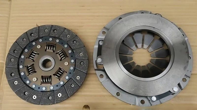
The face of a clutch pressure plate is rarely a perfect, unbroken circle. It often features bolt holes, lifting lugs, or balancing pockets. As the tool passes over these gaps, it experiences an interrupted cut3.
During an interrupted cut, the tool exits and re-enters the material violently. A sharp, positive cutting edge is too fragile for this impact. It will chip or fracture immediately upon re-entry.
To prevent this, you must apply a Negative T-land (Chamfer).
This is a small angled flat ground onto the cutting edge. It changes the direction of the cutting forces. Instead of the force pulling on the sharp edge (tensile stress), the T-land directs the force down into the body of the insert (compressive stress). PCBN is incredibly strong under compression but weak under tension.
Recommended T-land Configurations:
| Cutting Condition | Recommended T-land Angle | Recommended Width | Reason |
|---|---|---|---|
| Continuous Cut (Smooth surface) | 15° | 0.10 mm | Reduces cutting pressure; improves finish. |
| Light Interruption (Small holes) | 20° | 0.15 mm | Balances edge strength with cutting force. |
| Heavy Interruption (Large lugs/gaps) | 25° – 30° | 0.20 mm | Maximum edge protection against impact fracture. |
Using a T-land that is too large creates excessive heat and vibration. Conversely, a T-land that is too small offers zero protection.
Consider a similar situation in milling. When face milling a block with open slots, you would not use a sharp, high-positive aluminum insert for finishing. You would use an insert with a reinforced edge to handle the impact of the interruptions. The T-land on your PCBN insert serves the exact same purpose for the pressure plate.
Utilizing Wiper geometry inserts to double feed rates while maintaining Ra values
In mass production, cycle time is money. However, clutch pressure plates have strict surface roughness requirements, usually between Ra 0.8 and Ra 1.6.
With a standard nose radius insert, the surface finish is determined by the feed rate. If you feed the tool faster, the spiral grooves (scallops) left on the part become deeper and rougher. To get a smooth finish, you are forced to slow down the feed rate.
Wiper geometry solves this bottleneck.
A Wiper insert modifies the standard nose radius. It incorporates a small, straight flattening edge just behind the nose radius. This “wiper flat” smooths out the peaks of the spiral grooves as the tool moves forward.
Key Benefits of Wiper Geometry:
- Double the Feed: You can run at 2x the feed rate of a standard insert and still achieve the same surface finish.
- Superior Finish: If you keep the feed rate the same, the surface finish improves significantly (lower Ra).
For example, a standard ISO insert might require a feed rate of 0.15 mm/rev to achieve Ra 1.6. A Wiper insert can achieve that same Ra 1.6 while running at 0.30 mm/rev.
This geometry is essential for the “friction face” of the pressure plate. This surface must be smooth enough to engage the clutch disc but rough enough to seat properly.

Optimizing Cutting Parameters specifically for HT250 Pressure Plates
How should machine operators configure cutting speeds and depths when turning HT250 clutch pressure plates to prevent thermal damage and distortion?
To ensure quality when turning HT250 pressure plates, operators must maintain high surface speeds (typically 500–800 m/min for finishing) to induce necessary plasticization without creating a hardened white layer. Furthermore, the depth of cut must be kept minimal (0.15–0.30 mm for finishing) to reduce radial pressure on thin-walled sections, while strictly avoiding liquid coolant to prevent thermal shock fractures in the PCBN insert.
Balancing surface footage (SFM) to prevent thermal cracking and white layers
Gray cast iron (HT250) behaves differently than mild steel. To cut it effectively with PCBN, you actually need heat. The heat softens the metal just in front of the cutting edge. This process is called plasticization.
However, heat management is a balancing act. If the cutting speed (Surface Feet per Minute or SFM) is too low, the material stays cold and hard. This acts like an abrasive stone against the tool, causing rapid wear.
Conversely, if the speed is too high, you generate excessive heat. This extreme heat rapidly cools after the tool passes, creating a hard, brittle skin known as a white layer (martensite) on the pressure plate surface. A clutch pressure plate with a white layer will slip or shudder during vehicle operation because the friction characteristics are ruined.
Recommended Cutting Speed Ranges for HT250:
| Machining Stage | Speed (m/min) | Speed (SFM) | Objective |
|---|---|---|---|
| Roughing | 350 – 500 | 1150 – 1650 | Balance tool life with high material removal. |
| Finishing | 500 – 800 | 1650 – 2600 | Generate enough heat for a smooth surface finish. |
Think of this process like “Hard Turning” a hardened steel shaft. In both cases, you rely on speed to make the metal pliable at the shear zone. If you run too slow, you are just grinding the tool away. If you run too fast, you burn the part. You must find the “sweet spot” where the chips come off glowing hot, but the workpiece remains relatively stable.
Adjusting depth of cut strategies to minimize pressure on thin-walled plates
Clutch pressure plates often look like heavy, solid rings. However, many designs feature thin cross-sections to reduce weight. These thin areas make the part sensitive to cutting pressure.
If you set a heavy Depth of Cut (DOC), the PCBN insert pushes against the part with significant force. This causes the thin wall of the plate to deflect or bend slightly away from the tool. Once the tool passes and the pressure releases, the metal springs back.
This “spring back” results in dimensional errors. You might measure the part while it is clamped and find it acceptable. But once you unclamp it, the internal stress releases, and the surface becomes warped or “dished.”
Strategies to Minimize Deflection:
- Split the Cuts: Do not attempt to remove 1.0 mm of stock in one pass. Instead, take a roughing pass of 0.8 mm, followed by a finishing pass of 0.2 mm.
- The “Skim” Cut: For the final pass, the DOC should be slightly larger than the nose radius of the insert, but light enough to reduce push-off forces. A range of 0.15 mm to 0.30 mm is standard for finishing.
Consider the similarity to machining a thin brake rotor. If you push the tool too hard into the rotor face, the rotor flexes. You end up with thickness variation (DTV). The pressure plate requires the same delicate touch during the final pass to ensure the friction face remains perfectly flat.
Implementing dry cutting protocols to avoid thermal shock and coolant contamination
When using PCBN inserts on cast iron, you should almost always turn off the coolant pump.
Why avoid coolant?
- Thermal Shock: PCBN is a ceramic-based material. It operates best at high temperatures. If you flood a hot PCBN insert with cold coolant, the rapid temperature change causes the insert to crack. This is called thermal shock4. The cutting edge will crumble prematurely.
- Sludge Formation: Cast iron produces dust and small chips, not long stringy chips. When this fine iron dust mixes with coolant, it forms a thick, abrasive paste (sludge). This sludge can clog your chuck jaws and fixture locators.
Dry Cutting Best Practices:
- Air Blast: Instead of liquid, use a compressed air nozzle directed at the cutting zone. This blows the chips away from the surface so they are not re-cut.
- Dust Extraction: Cast iron turning creates graphite dust. Ensure your machine has a functioning vacuum or mist collector to keep the work area clean.
In rare cases where the part gets too hot to handle, you might use coolant only if the flow is high-pressure and continuous, ensuring the tool never heats up in the first place. However, for 90% of clutch plate applications, dry cutting is the industry standard for maximum tool life.
Troubleshooting Surface Finish and Dimensional Defects
What are the most effective methods to eliminate chatter, surface scratches, and parallelism errors when turning cast iron pressure plates?
To eliminate these common defects, operators must stabilize the workpiece using full-grip “pie jaws” to dampen vibration and reduce clamping distortion. Additionally, surface scratching is resolved by optimizing chip evacuation through directed air blasts, while parallelism is ensured by maintaining strictly clean fixture locators and machining the mounting reference points in the same setup whenever possible.
Eliminating chatter marks caused by workpiece vibration and clamping stress
Chatter is the enemy of any PCBN turning operation. On a clutch pressure plate, chatter appears as a distinct, wave-like pattern on the friction surface. Because PCBN inserts are extremely hard but brittle, severe chatter can cause the cutting edge to micro-chip or fracture completely.
Pressure plates are particularly prone to this because they are ring-shaped. Like a bell, they want to vibrate when struck by the cutting tool.
The primary culprit is often the clamping method. Standard 3-jaw chucks concentrate all the holding force on just three small points. This deforms the ring into a triangle shape and leaves large gaps unsupported, allowing vibration to build up.
Solution: Switch to Pie Jaws (Full-Grip Jaws)
The most effective fix is replacing standard hard jaws with Pie Jaws. These are soft jaws machined to wrap around the entire circumference of the pressure plate.
- Damping Effect: By contacting 90% or more of the outer diameter, the jaws act as a damper. They absorb the harmonic vibrations before they reach the surface finish.
- Reduced Distortion: Since the grip is spread out, you can lower the hydraulic chuck pressure. This prevents the “spring back” effect that happens when you unclamp a part that was squeezed too hard.
Note: Hydraulic pressure settings vary significantly between machine manufacturers. Always verify the minimum safe clamping pressure with your machine manual to prevent the part from slipping.
If you cannot use pie jaws, consider using a “face driver” setup where the part is pushed against a flat backing plate. This supports the rear of the friction face, preventing the thin wall from acting like a drum skin.
Resolving surface scratching issues from chip re-cutting or poor evacuation
Have you ever seen random, comet-shaped lines on an otherwise shiny pressure plate face? These are not caused by a dull tool. They are caused by “chip re-cutting.”
When turning gray cast iron (HT250), the material produces fine, granular chips—almost like heavy sand or dust. Unlike steel chips, which curl and break away, cast iron dust tends to settle on the part.
If these abrasive particles remain on the surface, the PCBN insert runs over them on the next revolution. The insert grinds the old chips into the fresh surface, leaving deep drag marks.
Strategies for Chip Evacuation:
| Evacuation Method | How It Works | Best Application |
|---|---|---|
| Air Blast | A high-pressure air nozzle aims directly at the cutting zone to blow dust away. | Standard horizontal turning centers. |
| Inverted Tooling | The tool holder is mounted upside down; the spindle rotates in reverse. | Allows gravity to pull chips down away from the surface. |
| Centrifugal Throw | Cutting from the Inner Diameter (ID) to the Outer Diameter (OD). | Uses the spinning force of the part to throw chips outward. |
Cutting direction is a critical variable here. If you cut from the outside moving inward (OD to ID), the centrifugal force works against you. It traps the chips inside the ring, causing them to tumble in front of the tool.
By programming the tool path to cut from the ID to the OD, you work with physics. As the tool cuts, the spinning motion of the pressure plate naturally flings the dust outward and away from the finished surface.
Correcting parallelism errors between the friction face and mounting surface
A clutch pressure plate has two critical jobs. First, it must provide a friction surface. Second, it must bolt flat onto the flywheel. If these two surfaces are not perfectly parallel, the clutch will wobble, leading to uneven wear and vibration in the vehicle.
Parallelism errors rarely come from the tool itself. They almost always come from the Locating Points (Datums) in your fixture.
The “Chip-Under-Part” Phenomenon
In a production environment, the biggest source of error is cast iron dust trapped between the part and the fixture.
Imagine a single grain of cast iron dust is 0.05 mm thick. If that grain gets stuck under one side of the pressure plate when you load it, the part sits crooked. You machine the face flat, but when you unclamp it, the part sits crooked again relative to its mounting lugs.
Corrective Actions:
- Fixture Hygiene: Automate a “locator wash” cycle. This uses a blast of coolant or air on the fixture pads before the robot or operator loads the next part.
- Datum Hierarchy: Always machine the “Mounting Lugs” (the points where the clutch bolts to the flywheel) in the same setup as the friction face if possible. If you machine them in one go, they are guaranteed to be parallel because the part never moved.
- Verification: Use a dial test indicator to sweep the back face of the part before turning. If the raw casting has a runout of more than 0.2 mm, the clamping force might warp the part. You may need to shim the part or machine a reference surface first.
If you observe that your parallelism error is consistently in one direction (e.g., always high on the X-axis), check your machine’s turret alignment. A crash or wear over time can cause the tool to travel at a slight angle, cutting a “dish” or “cone” shape instead of a flat plane.
Case Study: Reducing Cost Per Part for Heavy-Duty Truck Clutch Plates
Switching from conventional ceramic tools to Solid PCBN inserts often yields transformative results in heavy-duty applications. This case study details how a manufacturer achieved a 600% increase in tool life and a significant reduction in cycle time by implementing optimized PCBN strategies.
Baseline analysis of cycle time and tool life using conventional ceramic tools
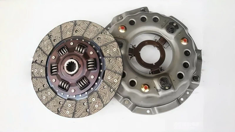
In this analysis, we examine a production line manufacturing 430mm diameter clutch pressure plates for heavy-duty trucks using HT250 gray cast iron. Originally, the manufacturer relied on Al2O3-based ceramic inserts (CNGA geometry).
The primary issue with ceramic tooling in this application was unpredictability. While ceramics are hard, they lack the toughness required for the heavy interruptions found on truck clutches. The casting surface often contained sand inclusions. When the ceramic tool hit a sand pocket or a lug gap, the cutting edge would micro-chip.
Operational Data (Baseline):
- Tool Life: The ceramic insert averaged only 12 parts per corner.
- Downtime: Operators had to stop the machine every 45 minutes to index the insert.
- Inconsistency: As the ceramic edge chipped, the surface finish (Ra) would rapidly deteriorate. This forced the operator to constantly measure parts and adjust offsets.
This frequent interruption drastically reduced spindle utilization rates, effectively turning a high-production lathe into a bottleneck. The machine was idle for tool changes far too often, driving up the labor cost per part.
Implementation of Solid CBN inserts with optimized turning paths
To solve the efficiency bottleneck, the process was upgraded to Solid CBN inserts (Grade equivalent to BN-S20 or similar high-content specifications). Specifically, an RNGN090300 round insert format was selected.
Why this change mattered:
- Solid Structure: Unlike the fragile ceramic, the Solid CBN material acts like a sintered composite structure that absorbs impact shocks. It simply plowed through the sand inclusions without chipping.
- Round Geometry (RNGN): The round shape is the strongest possible geometric form. It distributes cutting forces over a wider area than the diamond-shaped CNGA insert.
- Infinite Indexing: With a square or diamond insert, you have 4 fixed corners. With a round insert, the operator can rotate the insert just 15 degrees to find a fresh edge. This allows for 20+ “corners” on a single side.
Path Optimization:
The engineering team also adjusted the tool path. They programmed a variable depth of cut. Instead of cutting at the exact same depth on every pass (which creates a notch wear pattern), the tool path varied slightly. This technique spreads the wear across a larger section of the insert edge, further extending its usable life.
Final data comparison on production efficiency and scrap rate reduction
The results of the switch were immediate and measurable. While the initial purchase price of a Solid CBN insert is higher than a ceramic insert, the operational savings overwhelmed the upfront cost.
The following table details the specific performance metrics recorded over a 30-day production run:
| Performance Metric | Ceramic (CNGA) | Solid CBN (RNGN) | Improvement |
|---|---|---|---|
| Cutting Speed (Vc) | 350 m/min | 750 m/min | +114% |
| Feed Rate (fn) | 0.20 mm/rev | 0.35 mm/rev | +75% |
| Tool Life (Parts/Edge) | 12 parts | 85 parts | +608% |
| Tool Change Frequency | Every 45 mins | Every 4.5 hours | Reduced Downtime |
| Scrap Rate | 3.5% | 0.4% | Quality Improved |
Conclusion of Data:
The scrap rate dropped significantly because the Solid CBN edge held its size. With ceramics, the rapid wear caused the diameter to drift out of tolerance quickly. With PCBN, the dimension remained stable for hundreds of parts.
Furthermore, the machine spent more time cutting chips and less time waiting for an operator to change inserts. Even though the PCBN insert costs more to buy, one insert produced thousands of parts. Consequently, the total tool cost per finished part dropped by 28%, and overall production capacity increased without buying new machines.
Conclusion
Successfully turning clutch pressure plates is not merely about purchasing a harder cutting tool; it is about systematically addressing the unique challenges of HT250 cast iron. By shifting from standard ceramics to Solid CBN inserts with the correct negative T-land preparation, manufacturers can overcome the issues of sand inclusions and interrupted cuts.
However, the tool is only one part of the equation. To truly optimize production, operators must also adopt dry machining to prevent thermal shock, utilize pie jaws to dampen vibration, and optimize tool paths for better chip evacuation. As demonstrated in the case study, this holistic approach yields more than just extended tool life—it delivers a stable, high-efficiency process that significantly reduces the total cost per part.
References
- Gray cast iron1 – ZYDiamondTools guide on machining techniques specifically for hard cast iron materials using PCBN.
- Solid CBN inserts2 – ZYDiamondTools product page featuring Solid CBN inserts suitable for heavy-duty applications.
- Interrupted cut3 – ZYDiamondTools blog article explaining how PCBN tools provide the ultimate solution for interrupted cutting.
- Thermal shock4 – Wikipedia entry defining thermal shock and its effects on ceramic materials like PCBN.


