-
Whatsapp: +86 13526572721
-
Email: info@zydiamondtools.com
-
Address: AUX Industrial Park, Zhengzhou City, Henan Province, China
-
Whatsapp: +86 13526572721
-
Email: info@zydiamondtools.com
-
Address: AUX Industrial Park, Zhengzhou City, Henan Province, China

Struggling with PCD Drilling Flaws? How to Master Hole Accuracy, Eliminate Burrs, and Extend Tool Life

How can you consistently solve the most common issues in PCD drilling to achieve perfect holes and maximum tool efficiency?
Mastering PCD drilling involves a systematic approach to three core challenges. To ensure hole accuracy, you must guarantee system rigidity and optimize tool geometry and parameters. To eliminate burrs, you must maintain sharp cutting edges and control the drilling process at hole exit. Finally, to extend tool life, you must correctly identify wear, select the proper PCD grade, and effectively manage heat through coolant and chip evacuation.
How Do You Diagnose and Correct Hole Deviation?
So, what is the key to preventing a PCD drill from wandering off course and ruining a valuable part?
To correct hole deviation in PCD drilling, you must focus on four critical areas. First, ensure the machine tool and tool holder system are extremely rigid with minimal runout. Second, select a PCD drill with the correct point geometry for your specific material. Third, meticulously optimize cutting speeds and feed rates to balance performance and stability. Finally, for deep or critical holes, always implement a pilot hole strategy.
Hole deviation, also known as “walking” or “runout,” is a frequent challenge that can lead to scrapped parts and significant production losses. A drill that doesn’t follow its intended path creates holes that are oversized, out of position, or not perpendicular to the surface. Let’s break down each of the four key areas to ensure your holes are perfectly straight every time.
Analyzing Your Tool Holder and Machine Rigidity
Think of your machine and tool holder as the foundation of a building. If the foundation is unstable, the entire structure will be crooked. In the same way, if there is any instability in your setup, the drill will never produce a straight hole. The main culprit here is excessive runout.
What is Runout and Why Does it Matter?
Runout, or Total Indicated Runout (TIR), is the measure of how much a drill wobbles off-center as it rotates. Even a tiny amount of runout at the tool holder can be magnified at the drill tip, causing the drill to act like an out-of-balance tire and veer off course as soon as it touches the workpiece.
- Industry Standard: For high-precision drilling, a TIR of less than 0.01 mm (0.0004 inches) measured at the drill tip is often required.
- Case Study: An aerospace manufacturer drilling fastener holes in an aluminum fuselage panel (Alclad 2024-T3) was experiencing a high rejection rate due to hole position errors. An analysis showed their older mechanical collet chucks had an average runout of 0.025 mm. After switching to high-precision hydraulic chucks, runout was reduced to 0.005 mm, which completely eliminated the hole deviation problem and increased part acceptance by 98%.
How to Improve System Rigidity
- Choose the Right Holder: High-performance tool holders like hydraulic chucks or shrink-fit holders provide superior grip strength and the lowest possible runout compared to standard collet chucks. They clamp the drill shank with uniform pressure, ensuring it spins perfectly on-center.
- Inspect Your Machine Spindle: The machine’s spindle bearings can wear out over time, leading to increased runout. Regular preventative maintenance and inspection of the spindle are essential.
- Use the Shortest Tool Possible: The longer the drill and its overhang from the holder, the more it is prone to bending and deflecting under cutting forces. Always use the shortest drill that can achieve the required hole depth.
The Critical Role of PCD Drill Point Geometry
Not all drills are created equal. The shape of the drill’s tip, known as its point geometry, is perhaps the single most important factor in ensuring it starts and stays on course. Different materials require different geometries for optimal performance.
A drill’s ability to self-center is determined by its point angle and chisel edge design. A sharp, well-designed point acts like a guide, centering itself in the material before the main cutting edges engage.
The table below compares common point geometries and their effect on hole straightness.
| Drill Point Feature | Standard 118°/135° Point | Self-Centering 140° “Split Point” |
|---|---|---|
| Centering Action | Poor to Fair. Prone to “walking” at the start. | Excellent. The split point creates a small centering tip. |
| Thrust Force | Moderate. Requires significant force to penetrate. | Higher. Requires a rigid setup but offers better stability. |
| Ideal Application | General-purpose drilling in softer metals. | Hard, abrasive materials like high-silicon aluminum or composites. |
| Effect on Deviation | Higher risk, especially without a pilot hole. | Significantly lower risk due to superior centering. |
Professional Tip: Many PCD tool manufacturers have developed proprietary point geometries designed for specific material groups, such as drilling into Carbon Fiber Reinforced Polymer (CFRP). These specialized designs often feature a multi-facet point that reduces delamination and improves hole straightness. Because these geometries can vary, always consult your tool supplier’s catalog to select the ideal point design for your exact application.
Optimizing Speeds and Feeds to Maintain Straightness
While it might be tempting to push a drill as fast as possible to reduce cycle times, excessive cutting parameters can directly cause hole deviation. Finding the right balance between cutting speed (RPM) and feed rate (the speed at which the drill advances) is crucial for stability.
Imagine trying to push a thin wooden stick into the ground. If you push it too hard and fast (high feed rate), it will likely bend and break. But if you push it with steady, controlled pressure, it will go in straight. The same principle applies to drilling.
- Feed Rate: A feed rate that is too high generates immense lateral forces on the drill point, causing it to deflect, especially in non-uniform materials.
- Cutting Speed: A speed that is too low can increase torque and thrust, while a speed that is too high can cause premature tool wear, dulling the cutting edges and reducing their ability to cut cleanly and stay on path.
A good starting practice is:
- Begin with the PCD tool manufacturer’s recommended mid-range parameters for your specific material.
- If you observe hole deviation, reduce the feed rate by 10-15% as a first step. This lessens the cutting pressure and often stabilizes the drill.
- Only adjust the cutting speed (RPM) after you have optimized the feed rate, as speed has a greater impact on tool wear and heat generation.
Implementing a Pilot Hole Strategy for Deep Holes
When drilling holes where the depth is more than three times the diameter (3xD), or when positional accuracy is absolutely critical, is it wise to leave things to chance? A pilot hole is the most reliable method for guaranteeing hole straightness.
A pilot hole is a smaller, preliminary hole drilled on the exact center of the final hole. This simple step provides a perfect guide path for the larger PCD drill to follow, physically preventing it from walking or deflecting.
Key Guidelines for Effective Pilot Holes
- Diameter: The pilot hole should be slightly larger than the chisel edge of the final PCD drill but smaller than its full diameter. A common industry rule is to make the pilot hole approximately 50-60% of the final hole diameter.
- Depth: The pilot hole only needs to be deep enough to guide the point of the final drill, typically a depth equal to one time the pilot drill’s diameter is sufficient.
- Concentricity: It is essential that the pilot hole is perfectly concentric with the final hole. Use a high-precision, rigid spotting drill or the pilot drill itself to create a small starting dimple before drilling the full pilot hole.
What Are the Best Strategies to Eliminate Exit and Entrance Burrs?
How can you finally get rid of those frustrating, sharp burrs that ruin an otherwise perfect hole?
To eliminate burrs in PCD drilling, you should combine four effective strategies. First, ensure the drill’s cutting edge is consistently sharp and never dull. Second, program your machine to reduce the feed rate just before the drill exits the hole. Third, use PCD tools with specialized edge preparations or coatings designed for clean cutting. Finally, whenever possible, provide solid support by using a back-up material on the exit side of the workpiece.
Burrs are those small, sharp pieces of material left attached to the edge of a hole after drilling. They are not just unsightly; they can prevent parts from fitting together correctly, cause injuries during handling, and even break off during operation, leading to catastrophic failures in sensitive applications like engines or medical implants. Removing them requires extra, costly steps, so preventing them in the first place is always the best approach.
The Impact of a Dull Cutting Edge on Burr Formation
Think about slicing a tomato. With a sharp knife, you get a clean, perfect slice. With a dull knife, you just crush the tomato and make a mess. Drilling works the same way.
A sharp PCD cutting edge shears the material cleanly. In contrast, a dull or worn cutting edge stops shearing and starts plowing or pushing the material. Instead of being cut into a chip, the material at the edge of the hole gets plastically deformed—it’s bent and pushed out of the way. This pushed-out material is what becomes a burr.
- What to look for: A key sign of a dulling tool is a change in the cutting sound or an increase in the machine’s spindle load monitor. Because a dull tool requires more force, the machine has to work harder, which is a clear signal that the tool is ready for replacement before it starts producing heavy burrs.
- The Science: A sharp PCD edge might have an edge radius of only 2-5 micrometers (μm). A worn tool’s edge radius can easily increase to over 20 μm. This larger radius is what causes the plowing action instead of a clean shearing cut.
Key Takeaway: A sharp tool is the first and most important line of defense against burr formation. A disciplined tool management program, where drills are inspected and replaced regularly, is more cost-effective than a deburring program.
Adjusting Feed Rate and Spindle Speed at Hole Exit
The most critical moment for exit burr formation is the last fraction of a second before the drill breaks through the material. At this point, the material at the bottom of the hole is very thin and weak. If the drill pushes with too much force, this thin “membrane” of material will bend and tear rather than being cut.
So, how do you prevent this? You tell the machine to be gentler at the end.
The most effective strategy is to reduce the feed rate by 50-75% for the last 0.5 mm to 1.0 mm (0.020″ to 0.040″) of the hole depth.
- Example in Action: In automotive manufacturing, PCD drills are used to create thousands of holes in aluminum engine blocks. To ensure burr-free coolant and oil passages, the CNC program is often written with a “two-stage” feed rate.
- Stage 1 (Main Drilling): The drill runs at a high feed rate (e.g., 0.25 mm/rev) for the majority of the hole depth.
- Stage 2 (Exit): For the final 1.0 mm, the program automaticallyslows the feed rate down to 0.08 mm/rev. This drastic reduction in pressure allows the cutting edges to cleanly shear the final bit of material, creating a burr-free exit.
While adjusting the feed rate is the primary strategy, some machinists also slightly increase the spindle speed (RPM) during the exit. This can sometimes help achieve a crisper shearing action, but the effect is secondary to controlling the feed.
Leveraging Specialized Edge Preparations and Coatings
Sometimes, a simple “razor-sharp” edge isn’t the most durable or effective option, especially in tough or abrasive materials. Tool manufacturers have developed advanced edge designs to improve performance and reduce burrs.
Edge Preparation (Honing)
A honed1 or chamfered cutting edge has a tiny, intentionally rounded or angled edge. This might seem counterintuitive, but this micro-geometry strengthens the cutting edge, preventing it from micro-chipping. A chipped edge is effectively a dull edge, which, as we know, leads to burrs. This is especially useful in materials that are hard or contain abrasive particles.
Low-Friction Coatings
While the PCD tip itself is not coated, the steel body and flutes of the drill often are. A low-friction coating, such as Diamond-Like Carbon (DLC), acts like a non-stick pan for the drill. It helps chips slide out of the hole more easily.
- How does this help? Better chip evacuation means less heat and friction at the cutting zone. This leads to a more stable and clean cutting process, which indirectly reduces the tendency to form burrs.
A Note on Customization: The exact type of edge preparation (like the hone radius) or the best coating is highly dependent on the material you are drilling. It’s always best to consult your tool supplier. Tell them about your material and burr problems, and they can recommend a specialized geometry that is engineered to solve your exact issue.
Using Back-up Material for a Clean Breakthrough
One of the most reliable and straightforward ways to prevent an exit burr is to ensure the material has nowhere to go. By clamping a piece of back-up material tightly against the exit surface of your workpiece, you provide solid support during the drill’s breakthrough.
Imagine trying to poke a hole through a piece of paper held in the air—it will tear unevenly. Now, place that same piece of paper on a stack of newspapers and try again. You’ll get a clean, round hole because the newspapers supported the paper during the cut. That’s exactly how a backer works.
- What to Use: The ideal backer is a scrap piece of the same material you are drilling. However, other materials like aluminum, hard plastics (like Delrin), or even medium-density fiberboard (MDF) can work well.
- The Critical Rule: The back-up material must be clamped firmly against the workpiece. Any gap between the part and the backer will allow the material to bulge into the gap, forming a burr.
- Industry Example: When drilling thin-walled aluminum aerospace components, a custom-fit aluminum “sacrificial plate” is often clamped to the inside of the part. The drill goes through the main component and drills partially into the sacrificial plate. This guarantees that the exit hole is perfectly clean and burr-free, which is a non-negotiable requirement for aircraft safety.
Why Do PCD Drills Wear Out and How Can You Extend Their Life?
Are you wondering how to get the most out of your expensive PCD drills instead of replacing them prematurely?
Maximizing the life of a PCD drill requires a four-part strategy. First, you must correctly identify the specific wear pattern affecting the drill’s cutting edges. Second, select the optimal PCD grade with the right balance of hardness and toughness. Third, aggressively manage heat through efficient chip evacuation from the drill flutes. Finally, implement an advanced coolant strategy to protect the drill in the cut.
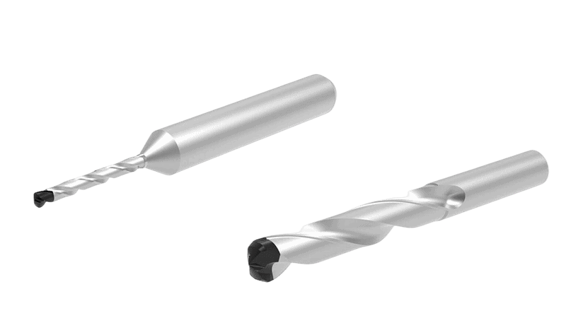
Polycrystalline Diamond (PCD) drills2 represent a significant investment, but their incredible hardness means they can last many times longer than carbide drills—if they are used correctly. Extending the life of your drills isn’t about luck; it’s about understanding why they fail and taking systematic steps to prevent it. By managing the factors that cause wear, you can make your tooling costs more predictable and your processes more reliable.
Identifying Common Wear Types on Drills
A PCD drill rarely just “gets old”; it fails in a specific way. Understanding how your drill is wearing down is like a doctor diagnosing an illness. Once you know the cause, you can apply the right cure. The three most common wear patterns seen on drills are abrasive wear, adhesive wear, and chipping.
Abrasive Wear
- What it looks like: The cutting edge corners and the flank face of the drill become smoothly rounded and dull over time.
- The cause: Think of it like running your hand over sandpaper. This type of wear is caused by hard particles within the workpiece material constantly grinding against the diamond edge during rotation. It is the most common and predictable type of wear when drilling highly abrasive materials, such as high-silicon aluminum3 (used in engine blocks), Metal Matrix Composites (MMCs), and carbon fiber composites.
Adhesive Wear
- What it looks like: Small pits or craters appear on the drill’s cutting edge, and you might see material from the workpiece stuck to the tool face (this is called a “built-up edge” or BUE).
- The cause: Imagine pressing a piece of sticky tape to a painted wall and ripping it off—some paint comes with it. This happens with “gummy” or chemically reactive materials like low-silicon aluminum or titanium. Tiny bits of the workpiece get pressure-welded to the hot drill tip and then break away, taking microscopic diamond particles with them.
Chipping
- What it looks like: Small nicks, cracks, or fractures along the drill’s primary cutting edge.
- The cause: This isn’t gradual wear; it’s physical damage. Chipping is often caused by instability, such as excessive machine vibration, a non-rigid tool holder, or an interrupted cut (like drilling through a cross-hole). It can also happen if the wrong, brittle PCD grade is used for a high-impact application.
Selecting the Optimal PCD Grade for Your Drill
Not all PCD is the same, and this is especially true for drills that face high thrust forces. PCD is engineered in different “grades” that offer a trade-off between wear resistance (hardness) and toughness4 (resistance to chipping). Choosing the wrong grade for your material is one of the fastest ways to destroy a drill.
The primary difference between grades is the size of the diamond crystals that are sintered5 together to create the PCD layer.
| PCD Grade Type | Diamond Grain Size | Key Characteristic | Best For… |
|---|---|---|---|
| Fine Grain | ~2-5 μm | Toughest. Resists chipping and impact fracture. | Interrupted cuts, less stable machining conditions, and materials where edge sharpness is critical. |
| Medium Grain | ~10 μm | All-Purpose. Good balance of toughness and wear resistance. | A wide range of non-ferrous metals and composites. The most common choice. |
| Coarse Grain | ~25+ μm | Most Wear Resistant. Highest hardness for long life. | Continuous, high-volume drilling in extremely abrasive materials like high-silicon aluminum or MMCs. |
- Case Study: An automotive supplier was drilling A390 aluminum (17% silicon) with a medium-grain PCD drill, achieving an average tool life of 15,000 holes before abrasive wear forced a change. By switching to a coarse-grain, highly wear-resistant PCD grade, they increased their average tool life to over 40,000 holes, drastically reducing tooling costs and machine downtime.
Always Check with Your Supplier: PCD grades are proprietary, and each manufacturer has its own naming system and specific formulations. To ensure you get the best performance, provide your tool supplier with the exact workpiece material specification and your primary tool failure mode (wear or chipping). They can then recommend the optimal grade.
The Role of Heat and Efficient Chip Evacuation
PCD is incredibly durable, but it has one major weakness: heat. If the cutting edge temperature gets above 700°C (1300°F), the diamond crystals can begin to break down and convert back into softer forms of carbon, leading to rapid wear.
What’s the main source of heat in a drilling operation? Friction. And the biggest source of friction is from chips rubbing against the drill as they are evacuated from the hole. Therefore, the single best way to keep a PCD drill cool is to get the chips out of the hole as quickly as possible.
- Drill Design: The design of the drill’s flutes (the spiral grooves) is critical. Wide, highly polished flutes act like a waterslide for chips, reducing friction and allowing them to exit easily.
- The Consequence of Poor Evacuation: If chips get packed in the flutes, they will grind against the drill and workpiece, generating massive amounts of heat. This not only destroys the PCD tip but can also damage the hole itself.
Advanced Coolant Strategies for Drilling
Coolant does two jobs: it lubricates to reduce friction and cools to remove heat. For high-performance PCD drilling, standard flood coolant is often not enough. Two advanced strategies are commonly used.
High-Pressure Coolant (HPC)
This involves pumping coolant directly through channels inside the drill at very high pressures, often over 70 bar (1000 PSI). The high-pressure jets act like a power washer, blasting chips out of the hole from the point of creation.
- Advantages: Excellent cooling and unbeatable chip evacuation, especially in deep holes. It’s the most effective way to manage heat and prevent chip packing.
- Requirements: A machine tool with a high-pressure coolant system and “through-spindle” capability.
Minimum Quantity Lubrication (MQL)
MQL uses a very small amount of a high-quality oil lubricant mixed with compressed air, creating a fine aerosol mist. This mist is sent through the tool and coats the cutting edges.
- Advantages: It’s an extremely effective lubricant, drastically reducing friction and heat generation. It is also more environmentally friendly, as it eliminates the need for large tanks of coolant. The parts come out nearly dry. MQL is very common in high-volume automotive production.
- Requirements: An MQL-capable machine and spindle, as well as drills designed specifically with channels for the aerosol to pass through.
Conclusion
Achieving excellence in PCD drilling is not about finding a single secret trick, but about embracing a holistic and systematic process. From the machine’s spindle to the drill’s microscopic cutting edge, every element plays a crucial role. By focusing on the fundamentals—ensuring rigidity, controlling cutting parameters, maintaining sharp tools, and managing heat—you can transform unpredictable flaws into consistent, high-quality results. This disciplined approach is the key to mastering hole accuracy, eliminating burrs, and truly maximizing the long life and value of your PCD tooling.
References
- honed1 – A ZYDiamondTools article explaining the related concept of edge radiusing (honing) on PCD inserts to enhance performance.
- Polycrystalline Diamond (PCD) drills2 – The official product page for ZYDiamondTools’ PCD drilling tools for various non-ferrous materials.
- high-silicon aluminum3 – A ZYDiamondTools guide to solving the challenges of machining high-silicon aluminum with PCD tooling, featuring real-world case studies.
- wear resistance (hardness) and toughness4 – An in-depth analysis from ZYDiamondTools explaining the key mechanical properties of PCD, including hardness and toughness.
- sintered5 – A ScienceDirect topic page explaining the engineering process of sintering materials together.


