-
Whatsapp: +86 13526572721
-
Email: info@zydiamondtools.com
-
Address: AUX Industrial Park, Zhengzhou City, Henan Province, China
-
Whatsapp: +86 13526572721
-
Email: info@zydiamondtools.com
-
Address: AUX Industrial Park, Zhengzhou City, Henan Province, China

How to Select and Apply PCD Chipbreaker Inserts for Optimal Machining Performance?

Selecting and using specialized tools like PCD (Polycrystalline Diamond)1 chipbreaker inserts can seem complex, so how do you navigate the choices and ensure you get the best performance possible?
Selecting the right PCD chipbreaker insert involves understanding why chipbreakers are needed for specific materials (like aluminum), identifying key features (PCD grade, geometry, edge prep), while optimal application requires establishing correct cutting parameters, ensuring machine rigidity, utilizing effective coolant strategies, and troubleshooting common issues.
Why Do You Need a Chipbreaker on PCD Inserts?
You might know that PCD (Polycrystalline Diamond) inserts are incredibly hard and great for cutting certain materials, but why do they sometimes need a special feature called a chipbreaker?
Essentially, chipbreakers are added to PCD inserts to safely manage the long, tangled chips produced when cutting softer metals like aluminum or copper. This control leads to better part quality, protects the workpiece and tool from damage, and makes automated machining much more reliable and safe.
Overcoming Poor Chip Control in Ductile Materials (e.g., Aluminum)
Certain materials, especially non-ferrous metals like aluminum and copper, are known as ductile. Think of them like taffy – they tend to stretch and form long, continuous strands before breaking when you cut them. While PCD tools cut these materials very efficiently, they often create these long, stringy chips without a chipbreaker.
So, what’s the problem with long chips?
Imagine long metal ribbons tangling everywhere! These chips can wrap around the cutting tool, the tool holder, or even the part itself. This tangle, sometimes called a “bird’s nest,” can cause several issues:
- Machine Stoppages: The tangled mess can force the machine to stop, requiring someone to manually clear it out. This downtime significantly hurts productivity, especially in high-volume production.
- Tool or Part Damage: Packed chips can interfere with the cutting action, potentially damaging the expensive PCD insert or gouging the workpiece.
- Safety Risks: Clearing sharp, tangled metal chips by hand is dangerous.
This is precisely where a chipbreaker becomes essential. It’s a specially designed groove or shape molded onto the top surface of the PCD insert. Its job is simple but crucial: to force the long chip to curl up tightly and then break into shorter, more manageable segments. Think of trying to neatly handle a long piece of tape versus short, pre-cut strips – the short strips are much easier to manage.
For instance, in automotive manufacturing, machining aluminum engine blocks or wheels at high speeds is common. Without effective chip control from chipbreakers, machines might stop frequently just to clear chips. Studies in such environments have shown that well-designed chipbreakers on PCD tools can reduce machine downtime related to chip problems by over 50%, directly boosting output.
Improving Surface Finish and Reducing Workpiece Damage
Uncontrolled chips don’t just cause downtime; they can also ruin the quality of the part you’re making. When those long, stringy chips aren’t broken effectively, they can easily get dragged across the surface that was just cut.
- Surface Scratches: Imagine a loose thread snagging on a smooth piece of fabric – a similar thing happens when a chip rubs against the freshly machined surface, leaving scratches or drag marks. This compromises the required surface finish, which is often critical for performance or appearance.
- Workpiece Gouging: If chips get packed tightly into the cutting area, they can get trapped between the tool’s flank (side) and the workpiece. This can cause deeper gouges or damage delicate features on the part.
Chipbreakers solve this problem directly. By breaking the chip into small, defined pieces, they allow coolant to easily flush the chips away from the cutting zone. The small chips are much less likely to interfere with the cutting edge or scrape against the finished surface.
The result?
A significantly improved surface finish, often closer to a mirror-like quality, especially important in applications like aerospace aluminum components where surface integrity is vital for fatigue life. Furthermore, preventing chip-related damage reduces the number of scrapped parts, saving material and costs. For example, machining hydraulic valve bodies from aluminum requires very smooth internal surfaces for proper sealing. PCD inserts with optimized chipbreakers ensure these surfaces are free from chip damage, reducing rejection rates.
Enhancing Automation Compatibility and Operator Safety
Modern manufacturing heavily relies on automation – CNC machines and robots running with minimal human supervision, sometimes even “lights-out” overnight. Long, unpredictable chips are a major enemy of reliable automation.
- Interfering with Automation: Tangled chips can trigger machine sensors incorrectly, jam chip conveyors, or wrap around robotic grippers, bringing the automated process to a halt and requiring human intervention.
- Enabling Unattended Machining: Chipbreakers produce consistent, small chips that automated systems can easily handle. Coolant flow typically washes them away efficiently into chip bins or conveyors. This predictability is fundamental for achieving long periods of unattended or minimally attended machining, maximizing machine utilization and efficiency.
Beyond automation, operator safety is paramount. Manually reaching into a machine tool to remove tangled, razor-sharp metal chips is one of the more common ways operators get cut in a machine shop.
- Reducing Manual Intervention: By automatically breaking the chips into small, less hazardous pieces, chipbreakers drastically reduce the need for operators to manually clear chips from the cutting zone.
- Lowering Injury Risk: Fewer manual interventions directly translate to a lower risk of cuts and related injuries.
Consider a facility producing thousands of copper electrical connectors daily. Switching to PCD inserts with effective chipbreakers might not only boost output by allowing longer automated runs but could also lead to a measurable decrease (potentially upwards of 70%) in manual chip-clearing actions and related safety incidents, creating a safer work environment.
Which Materials and Applications Benefit Most from PCD Chipbreakers?
Okay, we understand why chipbreakers on PCD inserts are helpful. But where do they actually make the biggest difference? In which specific situations should you really consider using them?
PCD chipbreaker inserts show their greatest advantages when machining non-ferrous metals that tend to produce long, difficult-to-control chips. This includes most aluminum alloys, copper, and brass. They are particularly effective in common operations like turning and boring, especially during finishing passes where surface quality is critical.
Excelling in Aluminum Alloys (Low vs. High Silicon Content)
Aluminum alloys are undoubtedly the number one place where PCD tooling shines2, and consequently, where PCD chipbreakers are most frequently needed. Why? Because standard cutting tool materials wear out quickly against aluminum, especially at the high speeds PCD can handle. However, aluminum is very ductile, meaning it stretches and forms those long, problematic chips we discussed earlier.
PCD chipbreakers help manage this, but it’s useful to know aluminum alloys differ:
- Low Silicon Aluminum Alloys (Typically <12% Si):
- These are very common (like 6061 or 7075 grades used for many structural or visual parts).
- They are extremely ductile, sometimes feeling almost “gummy” during machining. This makes them highly prone to long, stringy chips and also “built-up edge” (where material welds itself temporarily to the tool tip).
- Chipbreakers are extremely valuable here. They are essential for breaking the gummy chips and often work alongside sharp PCD edges to minimize built-up edge. Think about machining shiny aluminum wheels for cars – you need a great finish and reliable chip control, making PCD chipbreakers ideal.
- High Silicon Aluminum Alloys (Typically >12% Si):
- These alloys (like A390 used in engine pistons or blocks) contain hard silicon particles, making them very abrasive.
- PCD itself is needed here mainly for its hardness to resist wearing down quickly against the silicon.
- While these alloys are less gummy than low-silicon types, they can still produce continuous chips, especially at the high cutting speeds PCD allows.
- Chipbreakers remain beneficial for managing these chips and ensuring reliable, high-speed machining. The chipbreaker geometry might also be slightly different to help protect the cutting edge from the abrasive silicon.
In short, whether dealing with gummy low-silicon or abrasive high-silicon aluminum, PCD chipbreakers make the high-speed, efficient machining that PCD is known for much more practical and reliable by controlling the chips.
Effectively Machining Copper, Brass, and Other Non-Ferrous Metals
Beyond aluminum, PCD chipbreakers are also highly effective in other common non-ferrous metals that share similar machining challenges:
- Copper: Pure copper is very soft, ductile, and conductive (used in electrical parts like busbars or heat sinks). It’s notorious for producing long, difficult chips and suffering from built-up edge. PCD chipbreakers are a significant help in achieving clean cuts and preventing chip nests.
- Brass and Bronze: These copper alloys are generally easier to machine than pure copper. However, especially with modern lead-free brass formulations or when machining at high speeds, chip control can still be necessary for consistency and surface finish. PCD chipbreakers provide that reliable chip management for applications like plumbing fittings or bearing bushings.
- Magnesium Alloys: These lightweight metals machine easily, but good chip control is still beneficial for automated processes and managing the potentially flammable fine chips (though safe machining practices are key here regardless of the tool).
For most common non-ferrous metals where PCD is the preferred tool material due to wear resistance or achievable finish, adding a chipbreaker tackles the inherent challenge of managing ductile chips, leading to smoother operations.
Considerations for Composites, Plastics, and Wood Materials
PCD inserts are also frequently used for materials beyond metals, primarily because PCD is extremely hard and wear-resistant, or because it can maintain a very sharp edge.
- Composites (CFRP, GFRP)3: Materials like Carbon Fiber Reinforced Polymer (CFRP) or Glass Fiber Reinforced Polymer (GFRP) are incredibly abrasive. PCD provides excellent tool life compared to carbide. However, chip formation is often different – producing abrasive dust or brittle fragments rather than long, stringy chips. While a chipbreaker geometry might sometimes influence dust evacuation or surface quality slightly, its primary role of breaking long chips is less relevant here. The sharpness and wear resistance of the PCD edge itself are usually the main focus.
- Plastics: There’s a huge variety of plastics. Some softer ones might form continuous chips where a chipbreaker could potentially offer some benefit. Others fracture more easily. PCD is often chosen for its ability to create a very sharp edge, providing clean cuts without melting the plastic. Chipbreaker use is less common than in metals and depends heavily on the specific plastic being machined.
- Wood and Wood Composites (MDF): Natural wood and especially composite materials like Medium Density Fiberboard (MDF) can be quite abrasive. PCD provides much longer tool life in routing, milling, or sawing these materials. Chipbreakers are sometimes incorporated into PCD tooling for wood, especially in grooving or routing, to help manage chip size and prevent clogging.
Overall, while PCD excels in these non-metallic materials, the chip-breaking function of a chipbreaker is generally less critical compared to its role in ductile metals like aluminum or copper. The primary reasons for using PCD here are usually wear resistance and edge sharpness.
Typical Operations: Turning, Boring, and Finishing Cuts
Where do you physically use these PCD chipbreaker inserts in the machine shop? They are most commonly found in these types of operations:
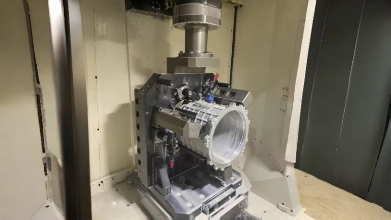
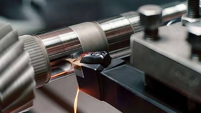
- Turning: This involves shaping the outside of a rotating workpiece. It’s a very frequent application, especially for continuous cuts on parts like aluminum automotive wheels, shafts, or pistons where high speeds are used and chip control is vital.
- Boring: This means machining the inside diameter of a hole. Getting chips out of a confined hole can be tricky. Small, broken chips created by a chipbreaker are much easier for coolant to flush out compared to long, stringy chips that can pack inside the bore, potentially breaking the tool or damaging the part. This is particularly important for deep holes or automated boring cycles.
- Finishing Cuts: These are light passes taken at the end of a machining process to achieve the final dimension and the required smooth surface finish. Even though the amount of material removed is small, ductile materials can still produce long, thin, wispy chips that can wrap around the part and scratch the surface. Chipbreakers ensure even these light chips are broken cleanly, protecting the crucial final surface quality.
While primarily used in these areas, the principles of chip control also make them beneficial in related operations like grooving (cutting narrow channels) or facing (machining a flat surface on the end of a part) when working with challenging non-ferrous materials. Remember, PCD tools (with or without chipbreakers) are generally not used for machining steels or other ferrous materials due to chemical reactions at high temperatures.

What Key Features Differentiate PCD Chipbreaker Inserts?
Okay, I know I need a PCD chipbreaker insert, but how do I tell them apart and choose the best one?
Key features differentiating PCD chipbreaker inserts include the specific PCD grade (affecting hardness and toughness), the chipbreaker geometry design (influencing chip curl and breaking), the nose radius (impacting strength and finish), edge preparation (enhancing durability), and the overall insert shape and size (determining compatibility with toolholders).
Understanding PCD Grades (Grain Size, Wear Resistance vs. Toughness)
Think of “PCD grade” as the specific recipe used to make the Polycrystalline Diamond cutting tip. Different PCD grades give you slightly different cutting properties. The biggest difference often comes down to the size of the tiny diamond crystals used, called the grain size.
- Fine Grain PCD: Uses very small diamond crystals. This allows for an extremely sharp cutting edge, which is great for getting a super smooth surface finish, especially on softer materials like low-silicon aluminum or copper. However, it can be a bit more brittle or prone to chipping if things get rough.
- Medium Grain PCD: Uses slightly larger crystals. This is often a good all-around choice, balancing good sharpness and finish with decent toughness and resistance to wear. It’s versatile for many common aluminum machining jobs.
- Coarse or Mixed Grain PCD: Uses larger diamond crystals, sometimes even a mix of sizes. This makes the PCD tougher and more resistant to chipping or breaking suddenly. It’s better for situations with interruptions (like cutting across a hole) or when machining more abrasive materials like high-Si aluminum or composites. The trade-off might be a slightly less sharp edge compared to fine grain, which could affect the absolute best achievable finish.
Here’s a simple way to think about the main trade-off, using sandpaper as an analogy for how grain size affects performance:
| Feature | Fine Grain PCD | Coarse Grain PCD |
|---|---|---|
| Primary Benefit | Highest Sharpness | Highest Toughness |
| Best For | Excellent Finish | Interrupted Cuts |
| Wear Type | Resists gradual wear | Resists chipping |
| Potential Drawback | More brittle | Slightly less sharp edge |
| Analogy | Fine grit sandpaper (smooth finish, wears faster on rough) | Coarse grit sandpaper (tougher, rougher finish) |
Important Note: PCD grade names (like Brand X’s “Grade 10” or Brand Y’s “Grade Z”) are specific to each manufacturer. They don’t always directly compare across brands. Therefore, it’s crucial to look at the manufacturer’s information for each specific grade to understand its intended use (material type, operation) and properties (like grain size or toughness level). Don’t hesitate to ask the supplier for recommendations.
Exploring Different Chipbreaker Geometries (e.g., 3D Designs, Rake Angles)
The “chipbreaker geometry” is the exact shape of the groove or feature molded onto the insert’s top face. This shape is what actually does the work of curling and breaking the chip. Designs can vary a lot:
- Simple Grooves: Some designs are relatively basic grooves.
- Complex 3D Designs: Many modern PCD chipbreakers have sophisticated, three-dimensional shapes. These are often created using advanced techniques like laser ablation. These 3D designs are generally more effective because they can control the chip’s curl and break point more precisely across a wider range of cutting conditions (like different depths of cut or feed rates). Manufacturers often give these special names (e.g., “NS,” “NLD,” “GD”).
- Rake Angle Influence: The chipbreaker design also influences the rake angle – the angle at which the cutting face meets the material. Positive rake angles usually mean lower cutting forces (easier cutting) but a slightly weaker edge, often good for finishing. Neutral or slightly negative rakes might be used for stronger edges.
- Application-Specific Geometries: Sometimes, manufacturers offer chipbreakers specifically tuned for certain tasks, like fine finishing versus general-purpose machining. A finishing chipbreaker might be designed to work best at very light depths of cut, while a general-purpose one might handle a broader range.
The geometry directly impacts how well the chip breaks under different conditions. A well-designed 3D chipbreaker might provide excellent control when taking both a light 0.5mm cut and a heavier 2mm cut, whereas a simpler design might only work well in a narrow range.
Remember: The effectiveness of a specific chipbreaker geometry depends heavily on the manufacturer’s design and testing. Performance can differ significantly between designs, so it’s wise to check supplier recommendations or test results for the cutting conditions (depth of cut, feed rate) you plan to use.
The Impact of Nose Radius and Edge Preparation Selection
Two other critical features that affect performance and how the insert is used are the nose radius and the edge preparation.
- Nose Radius (R): This is simply the size of the rounded corner on the cutting tip.
- A smaller radius (e.g., 0.2mm or 0.4mm) is needed to cut into tight corners or create small fillets on the part. It also generally leads to lower cutting forces. However, this small corner is less strong.
- A larger radius (e.g., 0.8mm or 1.2mm) makes the corner much stronger and more durable, better for general use or slightly heavier cuts. But, you can’t cut into corners smaller than the radius itself.
- The choice involves balancing the need for strength against the need to machine small features or achieve the lowest possible cutting force.
- Edge Preparation: This refers to how the actual cutting edge is treated after it’s made sharp.
- Sharp Edge: No special treatment. This provides the cleanest cut, lowest forces, and best potential finish, especially in soft materials like aluminum. It’s also the most fragile edge.
- Hone: A microscopic rounding of the sharp edge. This adds a small amount of strength to prevent tiny chips without significantly increasing cutting forces. It’s a very common preparation.
- Chamfer or T-Land: A small flat angle ground onto the edge. This makes the edge much stronger and more resistant to chipping, essential for interrupted cuts (like cutting across slots) or more abrasive materials. However, it increases cutting forces compared to a sharp edge.
Selecting the right nose radius and edge preparation is vital for balancing tool life, surface finish needs, and preventing premature tool failure. For example, a finishing pass on aluminum might use a small radius (0.4mm) with a sharp edge, while a general-purpose cut in high-silicon aluminum might use a larger radius (0.8mm) with a hone or even a light T-land for durability.
Check Options: Standard nose radii and edge preparations offered can vary between insert types and manufacturers. Always confirm the available options and discuss your specific application with the tooling supplier to get the best recommendation.
Standard ISO Shapes vs. Custom or Specialized Designs
Finally, PCD chipbreaker inserts come in various shapes and sizes, mostly following international standards.
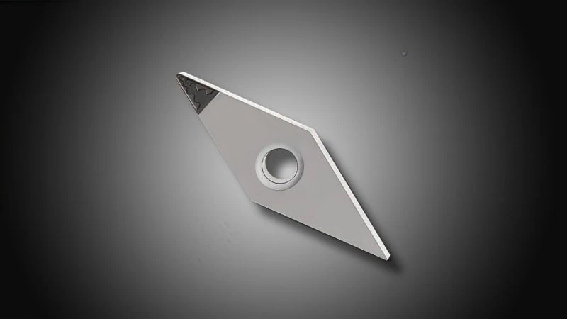
- Standard ISO Shapes: Most inserts adhere to ISO (International Organization for Standardization) standards. These standards define the shape, size, tolerances, and naming convention (like CNMG, DCGT, VCGT, TCGW).
- Shapes Examples: C (80° Diamond), D (55° Diamond), V (35° Diamond), T (Triangle), S (Square), R (Round).
- Benefit: The biggest advantage is interchangeability. An ISO-standard insert generally fits into any toolholder designed for that same ISO designation, regardless of the brand. This makes finding compatible holders easy.
- Custom or Specialized Designs: Occasionally, a standard shape won’t work for a highly specific task.
- This might involve unique insert shapes, multiple cutting edges on one insert, or features designed for special tooling systems.
- These are less common, usually developed for high-volume or unique manufacturing challenges in collaboration with a tool maker, and require specific, non-standard toolholders.
For most users needing PCD chipbreaker inserts, standard ISO shapes will be the most practical and widely available choice, offering flexibility and compatibility with existing toolholders.

How Can You Maximize Performance During Application?
You’ve selected your PCD chipbreaker insert based on the material, operation, and key features. So, how do you ensure you get the absolute best results when you actually put it to work in the machine?
Maximizing performance involves carefully setting the right cutting parameters (speed, feed, depth of cut) specifically for your PCD insert and material, ensuring your tool setup is extremely rigid, using coolant effectively to clear chips and manage heat, and knowing how to address common problems like built-up edge or poor chip flow.
Establishing Optimal Cutting Parameters (Speed, Feed, Depth of Cut)
Cutting parameters are the settings you program into the machine: how fast to cut, how quickly to move the tool, and how much material to remove at once. Getting these right is crucial for PCD chipbreaker inserts.
- Cutting Speed (Vc): This is where PCD truly shines, especially in non-ferrous materials. You can often run much faster than with carbide tools. For example, speeds of 500 to over 3000 meters per minute (roughly 1500 to 10,000 SFM or Surface Feet per Minute) are common when machining aluminum with PCD. Higher speeds usually mean better productivity and can often improve surface finish.
- Feed Rate (f): This is how fast the tool advances into the material per revolution of the workpiece (in turning) or per cutting edge (in milling). Feed rate directly impacts how thick the chip is. The chipbreaker is designed to work best within a certain range of chip thickness, so the feed rate is critical for making it function correctly. Feed also significantly affects the final surface finish.
- Depth of Cut (ap): This is how deep the tool cuts into the material in a single pass. Chipbreakers also have an optimal range for depth of cut. Too light a cut might not properly form a chip to engage the breaker; too heavy a cut might overload the insert edge or the chipbreaker geometry.
Finding the Sweet Spot: The goal is to balance these parameters. You want high speeds for productivity, but the feed and depth of cut must be suitable for the specific chipbreaker geometry to ensure chips break reliably without damaging the tool or the part.
Start with Recommendations: Always begin with the cutting parameter recommendations provided by the insert manufacturer. These are tailored to their specific PCD grade and chipbreaker design for various materials. They provide a safe and effective starting point.
Fine-Tuning: Observe the process.
* Are chips breaking cleanly? If not, and you’re within the recommended depth of cut, sometimes a slight increase in feed rate can help activate the chipbreaker more effectively (but stay within limits!).
* Is the surface finish good? If not, adjusting speed or feed might be needed.
* Does it sound smooth? A stable, smooth cutting sound usually indicates good parameters. Excessive noise or vibration suggests a problem.
Critical Supplier Note: Recommended cutting speeds, feeds, and depths of cut vary significantly based on the specific PCD grade, the exact chipbreaker geometry, the precise material being machined (e.g., 6061 vs. A390 aluminum), machine tool condition, and coolant usage. The numbers mentioned above are general examples only. Always consult your tooling supplier’s technical data for the specific insert you are using to get accurate starting parameters and application ranges.
Toolholder Selection and Rigidity Considerations
PCD is very hard, but like glass, it’s also brittle compared to tougher materials like carbide. This means it doesn’t tolerate vibration well. A setup that isn’t stiff, or “rigid,” will vibrate during cutting, and this vibration is a primary cause of tiny chips breaking off the PCD edge (micro-chipping), leading to poor tool life and bad surface finish.
- Choose Quality Holders: Use high-quality toolholders specifically designed for the insert shape (e.g., an ISO holder for an ISO insert). Ensure the pocket where the insert sits is clean and undamaged so the insert rests perfectly flat.
- Secure Clamping: Use the correct screw or clamp and tighten it to the manufacturer’s recommended torque specification. Do not overtighten, as this can crack the PCD. Do not under-tighten, as the insert could move during the cut.
- Minimize Overhang: This is crucial for rigidity. The “overhang” is how far the tool sticks out from the turret or spindle. Keep this distance as short as absolutely possible. Think of trying to bend a ruler – it’s much easier to bend if you hold it near one end and push far out on the other end. A shorter overhang makes the whole setup much stiffer and less prone to vibration.
- Machine Rigidity: The machine tool itself needs to be in good condition. Worn spindle bearings or loose machine slides will contribute to vibration.
A rigid setup allows the PCD chipbreaker insert to perform at its best, enabling you to use optimal cutting parameters without premature edge failure.
Effective Coolant Application Strategies
While PCD can handle heat well, coolant plays vital roles when using chipbreaker inserts, especially in non-ferrous metals:
- Chip Evacuation (Most Important!): This is often the #1 job for coolant when using chipbreakers. The coolant stream physically blasts the small, broken chips away from the cutting zone. This is critical to prevent chips from packing up, especially inside bores or deep grooves.
- Cooling: It helps keep both the tool and the workpiece at a stable temperature, preventing overheating which can affect part accuracy and tool life.
- Lubrication: Coolant provides some lubrication, which can help reduce friction and minimize the tendency for soft materials like aluminum to stick to the tool edge (built-up edge).
How to Apply It:
* Good Flow and Aim: Ensure a generous flow of coolant is accurately directed right at the cutting edge and helps push chips away from the work area.
* High-Pressure Coolant (HPC): If available, HPC (often 70 bar / 1000 psi or more) is highly effective. It acts like a power washer for chips. Many modern toolholders have internal channels that deliver HPC jets precisely where needed. This is particularly beneficial for boring and deep grooving where chip evacuation is naturally difficult.
Use a standard water-soluble coolant recommended for machining non-ferrous materials, maintained at the correct concentration. Effective chip evacuation via coolant is essential – if the broken chips aren’t removed, the chipbreaker isn’t providing its full benefit!
Troubleshooting Common Issues (Built-Up Edge, Chip Evacuation)
Even with careful setup, you might encounter issues. Here’s how to address some common ones:
- Problem: Built-Up Edge (BUE)4
- What it looks like: Material seems welded onto the very tip of the insert; surface finish on the part becomes poor, cloudy, or inconsistent.
- Try This: Often, increasing the cutting speed can help reduce BUE. Ensure good coolant flow. Consider using an insert with a sharper edge preparation if your application allows. Check if your supplier offers a specific PCD grade less prone to BUE for your material.
- Problem: Poor Chip Evacuation
- What it looks like: Chips (even if broken) are packing up in the cutting area, not washing away cleanly. This is common in boring or deep slots.
- Try This: Improve coolant delivery. Increase pressure and/or volume. Check nozzle aim – make sure it’s flushing chips out, not pushing them further in. Consider toolholders with internal or high-pressure coolant capabilities.
- Problem: Edge Chipping or Rapid Wear
- What it looks like: The insert corner breaks down quickly, doesn’t last as long as expected, leaves a bad finish, or cutting becomes noisy.
- Try This: First, check for vibration. Shorten tool overhang, ensure everything is tight and rigid. If vibration isn’t the issue, you might need a tougher PCD grade or a stronger edge preparation (like a hone or T-land). Consider slightly reducing the feed rate or depth of cut. Double-check the insert is seated correctly in the holder.
- Problem: Chips Not Breaking (Long, Stringy Chips)
- What it looks like: You’re still getting the tangled mess the chipbreaker was supposed to prevent.
- Try This: Make sure your feed rate and depth of cut are within the working range specified by the manufacturer for that specific chipbreaker geometry. Sometimes, too light a cut won’t engage the feature properly. If parameters seem correct, try slightly increasing the feed rate. Double-check you have the right chipbreaker design recommended for your specific material and type of cut (finishing vs. general purpose).
Conclusion
Selecting and applying PCD chipbreaker inserts effectively boils down to understanding the specific challenges of your machining task and matching them with the right tool features and application techniques. By recognizing why chipbreakers are crucial for materials like aluminum, knowing which materials and operations benefit most, carefully choosing inserts based on grade, geometry, and edge details, and applying them with optimal parameters, rigid setups, and good coolant practices, you can unlock significant gains. Addressing common issues promptly further ensures you achieve consistent chip control, excellent surface finish, enhanced productivity, and improved safety in your non-ferrous machining operations.
Referenced Links:
- PCD (Polycrystalline Diamond)1 – ZYDiamondTools blog post providing a comprehensive overview of PCD tools.
- PCD tooling shines2 – ZYDiamondTools blog exploring the benefits of PCD for aluminum machining.
- Composites (CFRP, GFRP)3 – ZYDiamondTools blog discussing PCD tooling for aerospace composites.
- Built-Up Edge (BUE)4 – Wikipedia article explaining the phenomenon of Built-Up Edge in metal cutting.