-
Whatsapp: +86 13526572721
-
Email: info@zydiamondtools.com
-
Address: AUX Industrial Park, Zhengzhou City, Henan Province, China
-
Whatsapp: +86 13526572721
-
Email: info@zydiamondtools.com
-
Address: AUX Industrial Park, Zhengzhou City, Henan Province, China

PCD Boring Bars: How to Select the Best Option for Your Needs?
With various options available, how do you actually choose the best PCD boring bar for your specific needs?
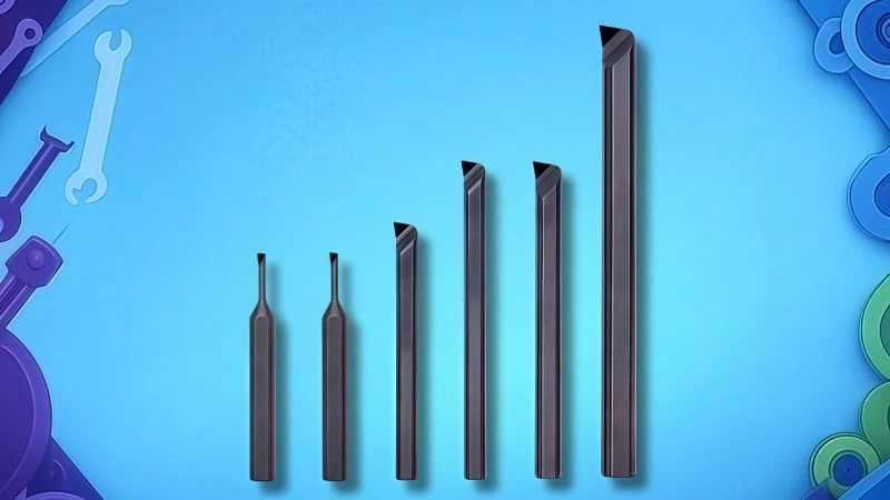
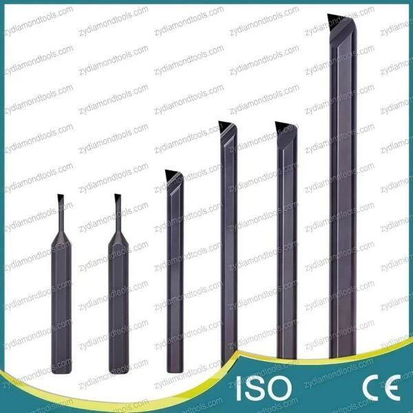
Selecting the best PCD boring bar, usually constructed with a PCD cutting tip brazed onto a steel or carbide shank, involves understanding prime applications (non-ferrous metals, abrasive non-metals), determining correct technical specifications (grade, geometry, shank, edge details, size), and knowing best practices for effective use (speeds, feeds, coolant, rigidity, handling) to maximize performance and tool life.
What Makes PCD Tipped Boring Bars a Superior Choice for Certain Applications?
So, what exactly makes PCD tipped boring bars[1] stand out for specific machining jobs?
PCD tipped boring bars offer exceptional performance primarily due to Polycrystalline Diamond’s extreme hardness and wear resistance. This makes them the superior choice for achieving excellent surface finishes, long tool life, and tight tolerances when machining non-ferrous metals like aluminum alloys, copper, and brass, as well as highly abrasive non-metallic materials such as composites (CFRP/GFRP) and green ceramics.
Let’s explore these advantages in more detail.
Unmatched Performance on Non-Ferrous Metals (Aluminum, Copper, Brass)
When your task involves machining non-ferrous metals – materials like aluminum alloys[2], copper, or brass – PCD tipped boring bars truly shine. Why is this the case? It boils down to the unique properties of Polycrystalline Diamond.
First, PCD has a very low chemical reactivity with these metals. Think of it like trying to get two non-stick pans to stick together – it just doesn’t happen easily. In machining, this prevents a common problem called Built-Up Edge (BUE), where tiny bits of the workpiece material weld themselves onto the cutting tool’s edge. Consequently, because BUE is minimized or eliminated with PCD:
- Mirror-like Finishes: The cutting action remains clean and smooth, often resulting in exceptional, mirror-like surface finishes on the workpiece. For instance, automotive parts like aluminum engine blocks or transmission valve bodies often require extremely smooth sealing surfaces to prevent leaks. PCD boring bars can frequently achieve surface roughness (Ra) values well below 0.4 micrometers, sometimes eliminating the need for later polishing or grinding operations.
- Higher Cutting Speeds: PCD’s incredible hardness allows you to run machines much faster compared to traditional carbide tools when cutting aluminum. Imagine needing to produce thousands of aluminum parts daily; PCD tools might allow cutting speeds (measured in Surface Feet per Minute or SFM) that are 5 to 10 times higher than carbide. This dramatically reduces the time it takes to make each part (cycle time), boosting overall productivity.
Excelling with Abrasive Non-Metallic Materials (Composites, CFRP, GFRP, Green Ceramics)
Now, let’s consider another group of challenging materials: highly abrasive non-metallics. This includes materials like:
- Carbon Fiber Reinforced Polymers (CFRP)[3] – common in aerospace and high-performance automotive parts.
- Glass Fiber Reinforced Polymers (GFRP) – used in boats, wind turbine blades, and various industrial components.
- Graphite composites.
- Green (unfired) Ceramics.
These materials act almost like sandpaper against a cutting tool edge due to their hard, abrasive internal structures (like carbon or glass fibers). Using conventional tools like carbide often leads to rapid wear.
This is where PCD’s extreme hardness and abrasion resistance become critical.
- Incredible Wear Resistance: PCD is one of the hardest materials known, second only to natural diamond. Therefore, it can withstand the intense abrasive wear from these materials far better than carbide. Consider machining an aircraft wing component made from CFRP. A carbide tool might wear out after only a short time, requiring frequent tool changes and machine downtime. In contrast, a PCD tipped boring bar in the same operation could potentially last 20 to 50 times longer, significantly cutting tooling costs and improving machine uptime.
- Maintaining Edge Quality: Because PCD resists wear so effectively, its cutting edge stays sharp and consistent for much longer. This is crucial when machining composites, as a dull edge can cause problems like fiber pull-out, delamination (layers separating), or poor surface quality. A sharp, durable PCD edge ensures consistent, high-quality results part after part.
Key Advantages Explained: Superior Surface Finish, Extended Tool Life, and High Precision
Let’s summarize the core benefits that make PCD tipped boring bars so valuable, stemming directly from PCD’s material properties:
- Superior Surface Finish: As mentioned, the low friction and ability to maintain a sharp edge, especially when machining non-ferrous metals, allow PCD tools to produce outstanding surface finishes. This often reduces or eliminates the need for secondary finishing processes, saving time and cost.
- Extended Tool Life: This is perhaps the most significant economic advantage. Due to its phenomenal hardness and wear resistance in suitable applications (non-ferrous and abrasive non-metals), PCD tooling can last dramatically longer than carbide tools. While the exact increase varies greatly with the specific material and cutting conditions, tool life improvements ranging from 10x to potentially over 100x compared to carbide are achievable in optimized scenarios. This means fewer tool changes, less machine downtime, and lower overall tooling expenditure per part.
- High Precision and Consistency: When a tool wears down, its shape changes, affecting the dimensions of the parts being machined. Because PCD tools wear so slowly and predictably, they maintain their precise cutting geometry for a much longer time. This leads to better dimensional accuracy, tighter tolerances, and greater consistency across large batches of parts. Consequently, operators need to make fewer adjustments (tool offsets) during production runs.
When to Choose PCD Over Carbide or CBN Boring Solutions
Choosing the right cutting tool material is essential for efficient and high-quality machining. While PCD is excellent for specific tasks, it’s not a universal solution. Here’s a simplified guide comparing PCD with Tungsten Carbide and Cubic Boron Nitride (CBN):
| Tool Material | Best For (Primary Applications) | Key Strengths | Key Limitations |
|---|---|---|---|
| PCD (Polycrystalline Diamond) | Non-Ferrous Metals (Al, Cu, Brass, Mg) Abrasive Non-Metals (Composites, Ceramics, Graphite) | Extreme wear resistance (in these materials), best surface finish, long tool life, high-speed capability (in Al) | Not suitable for ferrous metals (steel, cast iron) due to chemical reaction; can be more brittle than Carbide[4] |
| Carbide (Tungsten Carbide) | General Purpose Steels (low/medium carbon), Stainless Steels, Cast Irons, Titanium, High-Temp Alloys | Tough, versatile, relatively low cost, good performance across a wide range of materials | Wears quickly in highly abrasive materials; lower speed/life vs. PCD in aluminum; can cause BUE in some non-ferrous |
| CBN[5] (Cubic Boron Nitride) | Hardened Ferrous Metals (>45 HRC) Cast Irons, Superalloys, Sintered Metals | Very hard (second to diamond), maintains hardness at high temperatures (for hard turning/boring) | Not ideal for soft steels or non-ferrous metals; typically more expensive than carbide; can also be brittle |
In essence:
- Choose PCD for high-volume or high-precision boring of aluminum, copper, brass, composites, and other abrasive non-metals where tool life and surface finish are critical.
- Choose Carbide as a versatile, cost-effective option for boring most steels, stainless steels, and cast irons, especially when extreme tool life isn’t the primary driver or budgets are tighter.
- Choose CBN specifically for boring very hard steels (typically after heat treatment), difficult cast irons, or certain superalloys where high heat is generated.
Ultimately, the specific material being machined, the required production volume, surface finish specifications, and machine capabilities will guide the optimal tool material selection.
How Do You Determine the Right Specifications for Your PCD Boring Bar?
Choosing the right tool details is key, so how do you figure out the exact specifications needed for your PCD boring bar?
Determining the correct PCD boring bar specifications involves matching the PCD grade and cutting geometry to the workpiece material and type of cut. You also need to select the appropriate shank material (steel or carbide) and diameter for rigidity, choose suitable cutting edge details like nose radius and edge preparation, and consider the tool’s minimum bore capability and overall length relative to the application.
Selecting the perfect boring bar isn’t just about picking one off the shelf; it requires matching the tool’s characteristics to your specific job. Let’s break down the key specifications you need to consider.
Matching PCD Grade and Geometry to Your Specific Material and Cut
Not all PCD is created equal! Think of it like different recipes for the same type of cake – slight changes can make a big difference. The two main things to consider here are the PCD grade and the cutting geometry.
Understanding PCD Grades
The “grade” of PCD often relates to the size of the diamond crystals used to make it. This impacts how the tool performs:
- Coarser Grain Grades: These generally offer the highest wear resistance. They excel in highly abrasive materials like fiber-reinforced composites (CFRP/GFRP) or aluminum alloys with high silicon content (which act like tiny bits of sand).
- Finer Grain Grades: These grades can typically be honed to a sharper cutting edge and offer better edge toughness. This makes them ideal for achieving the absolute best surface finish on standard aluminum alloys, copper, or brass where extreme abrasion isn’t the primary concern.
Important Note: PCD grade designations and their specific properties can vary between manufacturers. Always consult your supplier’s recommendations or datasheets to select the most suitable grade for the specific material you plan to machine.
Basic Cutting Geometry
The shape and angles of the cutting edge also play a vital role:
- Rake Angle: This angle affects how the chip flows away from the cut and the amount of force needed. For softer non-ferrous metals like aluminum, a positive rake angle is often preferred as it shears the material more easily, reducing cutting forces and the chance of built-up edge. For tougher composites, different rake angles might be used to provide better edge strength.
- Clearance Angle: This is the angle providing space behind the cutting edge so the tool doesn’t rub against the surface it just cut. It needs to be large enough to prevent rubbing but not so large that it weakens the cutting edge.
Tool manufacturers design specific geometries optimized for groups of materials. Using a tool designed for aluminum to cut composites might not yield the best results, and vice versa.
Understanding Shank Material and Diameter Requirements (Steel vs. Solid Carbide)
The “shank” is the main body of the boring bar. The material of this shank, to which the PCD tip is brazed, significantly impacts performance, particularly rigidity (stiffness).
- Steel Shanks: These are generally more economical. They can be perfectly suitable for larger diameter boring bars or applications where extreme precision or long tool reach isn’t required. However, steel is less stiff than carbide.
- Solid Carbide Shanks: Carbide is significantly more rigid (possessing a higher Young’s Modulus[6] – essentially “stiffer”) and better at damping vibrations than steel. Think of trying to hold a long, thin steel rod perfectly still versus a similar carbide rod – the carbide one will flex much less. This extra rigidity is crucial for:
- Small diameter boring bars (where the shank itself is thin).
- Tools that need to stick out a long way from the holder (long overhang).
- High-precision boring operations where minimizing tool deflection is critical.
The downside? Carbide shanks are more expensive.
The Shank Diameter itself is also a major factor in rigidity – a thicker shank is much stiffer than a thinner one. However, the shank diameter also limits the smallest hole you can bore.
Selecting Appropriate Cutting Edge Details (Nose Radius, Edge Prep)
The fine details of the cutting edge itself influence both the cutting process and the resulting finish.
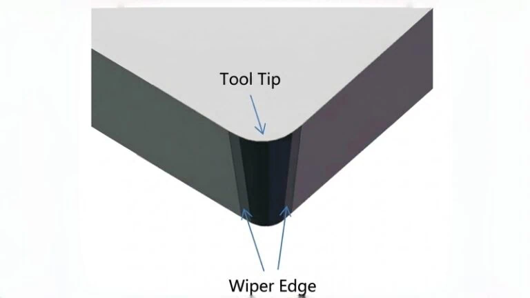
- Nose Radius (R): This is the radius on the corner of the cutting tip.
- A larger radius (e.g., 0.8mm) creates a stronger cutting edge, potentially allowing for faster feed rates and sometimes producing a smoother finish through a slight burnishing effect. However, it also increases cutting forces, particularly pushing the tool away from the workpiece (radial force).
- A smaller radius (e.g., 0.2mm) results in lower cutting forces and is better for creating sharp internal corners or fine details. The trade-off is a more delicate cutting edge.
- The choice involves balancing edge strength, desired finish, part geometry, and cutting forces. Standard nose radii are commonly available, but specific options can differ between suppliers, so it’s wise to verify available sizes with your tool provider.
- Edge Preparation (Edge Prep): PCD cutting edges can be incredibly sharp but also somewhat brittle right at the very edge. Edge preparation involves slightly modifying this edge to improve its strength and prevent tiny chips (micro-chipping), especially when the tool first enters the material or cuts across interruptions. Common types include a light hone (rounding) or a small chamfer (sometimes called a T-land). This adds strength but very slightly reduces the ultimate sharpness – a trade-off optimized by the manufacturer for specific applications (e.g., finishing vs. roughing).
Minimum Bore Diameter Capabilities and Tool Length Considerations
Two practical geometric limits are crucial:
- Minimum Bore Diameter (Min. Bore Ø): This is simply the smallest diameter hole that the boring bar head can physically fit into and machine effectively. It’s determined by the size of the cutting head and the shank diameter immediately behind it. You absolutely must choose a tool with a minimum bore capability smaller than the hole you intend to machine.
- Tool Length and Overhang: “Overhang” refers to how much the tool sticks out from the tool holder. This is critical for rigidity.
- Impact: Stiffness decreases dramatically as overhang increases (roughly by the cube of the length!). A long, skinny boring bar will be much more prone to bending and vibration (chatter) than a short, stout one. Imagine a diving board – the longer it is, the more it bounces.
- Consequences: Vibration leads to poor surface finish, inaccurate hole sizes, and can even cause the PCD tip to chip or break.
- Guideline: Always use the shortest boring bar possible that can still reach the required machining depth. Manufacturers often provide guidelines for maximum recommended overhang, often expressed as a ratio of length to diameter (e.g., L/D ratio of 4:1). Exceeding these limits significantly increases the risk of problems.
Standard Off-the-Shelf vs. Custom-Engineered PCD Boring Bars
Finally, you’ll need to decide between a standard tool or a custom one.
- Standard Boring Bars: These are tools with common sizes, geometries, and grades listed in supplier catalogs.
- Pros: Readily available, lower cost, faster delivery times, designs are proven for typical applications.
- Cons: May not be perfectly optimized for a unique material, a very specific tolerance requirement, or an unusual part geometry.
- Custom-Engineered Boring Bars: These are designed and manufactured specifically for a particular customer’s application.
- When to Consider: You might need a custom tool for:
- Machining non-standard bore sizes or reaching extreme depths.
- Creating complex internal profiles or features in one pass.
- Optimizing performance for a very specific or unusual workpiece material.
- Incorporating special features, like precisely aimed internal coolant channels.
- Maximizing efficiency and tool life in very high-volume, dedicated production lines (e.g., automotive manufacturing).
- Pros: Performance is tailored exactly to the need, potentially solving problems standard tools cannot. Can sometimes combine multiple operations into one tool.
- Cons: Higher upfront cost, significantly longer lead times for design and manufacturing, requires detailed discussion and collaboration with the tooling supplier.
- When to Consider: You might need a custom tool for:
Choosing between standard and custom often depends on the uniqueness of the application, the required performance level, production volume, and budget.
What Are the Best Practices for Using PCD Boring Bars Effectively?
Okay, you’ve selected your PCD boring bar, so how do you actually use it effectively to get the best results?
Using PCD boring bars effectively involves optimizing cutting speeds and feeds based on supplier recommendations and material, applying appropriate coolant (often flood or MQL), ensuring maximum rigidity in the machine tool and workholding setup, and handling the tools carefully to prevent chipping the PCD edge.
Getting the most out of your investment in PCD tooling means paying attention to how you apply and care for it during the machining process. Let’s look at the best practices.
Optimizing Cutting Speeds and Feeds for Performance and Longevity
Running a tool at the right speed and feed is crucial for both the quality of your part and how long the tool lasts. Let’s define these terms simply:
- Cutting Speed: This refers to how fast the cutting edge moves across the surface of the material you’re cutting. It’s often measured in Surface Feet per Minute (SFM) or meters per minute (m/min). On the machine, this translates to the spindle speed (RPM).
- Feed Rate: This is how quickly the tool advances into or along the workpiece. It can be measured per revolution (like Inches Per Revolution – IPR, or mm/rev) or per unit of time (like Inches Per Minute – IPM, or mm/min).
So, what are good starting points for PCD boring bars?
- In Aluminum Alloys: PCD truly excels here, allowing for significantly higher cutting speeds than carbide. Speeds ranging from 1000 to 6000 SFM (approx. 300 to 1800 m/min) or sometimes even higher are common, depending on the specific alloy and machine capability. Feed rates will vary based on whether you’re roughing (removing material quickly) or finishing (aiming for a smooth surface).
- In Composites/Abrasive Non-Metals: Cutting speeds might need to be more moderate compared to aluminum, often to manage heat generated by friction and prevent damage to the workpiece material (like delamination in composites). Feeds are also typically controlled carefully to ensure clean shearing of fibers or particles.
Crucially, Optimization is Required: The ranges mentioned above are just general guidelines. The ideal speeds and feeds for your specific job depend heavily on factors like:
- The exact material being cut (e.g., high-silicon aluminum vs. standard 6061 aluminum).
- The rigidity of your machine and setup (more on this later).
- The depth and width of the cut.
- The required surface finish.
- The specific PCD grade and tool geometry.
Recommendation: Cutting speeds and feeds are highly application-specific. Always start with the recommendations provided by your tool supplier for the specific tool and material combination. Then, make small, careful adjustments (perhaps +/- 10% increments) while closely monitoring the cutting sound, chip formation, surface finish, and tool wear to find the “sweet spot” for your operation.
Coolant Application Strategy: Flood, MQL, or Dry Machining?
Coolant (or cutting fluid) plays several roles: it cools the tool and workpiece, lubricates the cutting action, and helps flush away chips. With PCD, the strategy matters:
- Flood Coolant: Applying a generous, continuous stream of coolant directly at the cutting zone is often very effective, especially when machining aluminum alloys. It provides excellent cooling and helps wash chips out of the bore, which is critical in a confined space.
- MQL (Minimum Quantity Lubrication): This technique uses a tiny amount of specialized lubricant mixed with compressed air, sprayed as a mist. MQL can be effective, particularly when machining composites where flood coolant might be undesirable or absorbed by the material. The air blast also aids significantly in chip evacuation. It’s also more environmentally friendly.
- Dry Machining: Sometimes, particularly for light finishing cuts or certain composite materials, machining completely dry (perhaps with an air blast for chip removal) is possible due to PCD’s low friction properties. Chip evacuation becomes critical here.
Key PCD Consideration – Avoid Thermal Shock[7]: PCD is very hard, but it doesn’t like sudden, drastic temperature changes. If you choose to use coolant, ensure it’s applied consistently and copiously. Intermittent coolant application (splashing on and off) can cause tiny thermal cracks in the PCD structure, leading to premature edge failure. The rule is generally: use plenty of coolant consistently, or use none at all (with effective chip removal). Avoid situations where the edge gets hot then suddenly quenched repeatedly.
The Critical Role of Machine Tool and Workholding Rigidity
We mentioned rigidity when discussing shank materials, but the stability of the entire system – the machine tool and how the part is held – is equally vital for PCD success. Why? Because PCD performs best in smooth, stable cutting conditions. Vibration (chatter) is its enemy.
- Machine Tool Rigidity: The overall stiffness and condition of your CNC machine matter. A machine with worn spindle bearings or a less robust structure might vibrate, especially at the high speeds PCD is capable of. This vibration transfers to the tool, potentially chipping the delicate PCD edge and ruining the surface finish.
- Workholding Rigidity: How securely the workpiece is clamped is critical. If the part can move or vibrate even slightly during boring, it will cause inconsistencies and likely damage the tool.
- Use sturdy, high-quality fixtures.
- Clamp the workpiece as close as possible to the area being machined.
- Ensure the part is well-supported to prevent flexing under cutting forces.
- Analogy: Imagine trying to drill a precise hole while holding the part loosely in your hand versus having it clamped firmly in a vise. The stable setup allows for accuracy and prevents chatter.
- Tool Holder Quality: The holder connecting the boring bar to the machine spindle (e.g., hydraulic chuck, precision collet chuck) must also be rigid, accurate (low runout), and clean to ensure the tool runs true and vibration is minimized.
A rigid setup allows the PCD tool to cut smoothly, achieving its full potential for precision, finish, and tool life.
Handling and Maintenance Tips for PCD Tooling
While incredibly hard and wear-resistant in the cut, the PCD tip can be surprisingly easy to damage through improper handling outside the machine. Think of it like ceramic – very hard, but brittle if dropped.
- Handle with Care: Never drop or bump the boring bar, especially near the cutting edge or the braze joint. Even a small impact against another tool or a hard surface can chip the PCD or potentially damage the integrity of the brazed connection.
- Protective Storage: Always store PCD tools in their original protective packaging or individual padded containers. Don’t just toss them loosely into a toolbox drawer where they can bang against other tools. Use protective caps over the tips whenever possible.
- Careful Mounting: When installing the boring bar into a tool holder, ensure both the tool shank and the holder bore are perfectly clean. Any dirt or debris can cause the tool to sit improperly, leading to runout and potential damage. Handle the tool carefully during this process.
- Regular Inspection: Make it a practice to inspect the PCD cutting edge regularly under magnification (using a toolmaker’s microscope or a good quality loupe, perhaps 10x-20x). Look for tiny chips or signs of unusual wear. Catching minor damage early allows you to replace the tool before it fails completely in the cut, potentially scrapping an expensive part or causing further damage.
Treating your PCD tooling with care outside the machine is just as important as using the right parameters inside the machine to maximize its life and performance.
Conclusion
Choosing and using the right PCD boring bar can significantly enhance your machining operations for non-ferrous metals and abrasive non-metallics. By carefully considering the application, selecting the appropriate specifications based on material, geometry, size, and rigidity needs, and adhering to best practices for speeds, feeds, coolant application, and careful handling, you can unlock the full potential of PCD tooling. This approach allows you to consistently achieve superior surface finishes, benefit from extended tool life, and maintain exceptional precision in your boring tasks.
If you have specific PCD boring bar requirements or questions about selecting the right tool for your application, you can contact us for expert advice and solutions.
References
- PCD tipped boring bars1 – ZYDiamondTools product page for PCD and PCBN boring bars.
- aluminum alloys2 – ZYDiamondTools blog post discussing the benefits of PCD tooling for machining aluminum.
- Carbon Fiber Reinforced Polymers (CFRP)3 – ZYDiamondTools blog post on using PCD tools for aerospace composites like CFRP.
- Carbide4 – ZYDiamondTools blog post detailing the comparison between PCD and Carbide cutting tools.
- CBN5 – ZYDiamondTools blog post comparing PCD and CBN cutting tools.
- higher Young’s Modulus6 – Engineering ToolBox page explaining Young’s Modulus (Modulus of Elasticity) with values for various materials including steel and tungsten carbide.
- Thermal Shock7 – ScienceDirect topic page defining thermal shock in materials science.