-
Whatsapp: +86 13526572721
-
Email: info@zydiamondtools.com
-
Address: AUX Industrial Park, Zhengzhou City, Henan Province, China
-
Whatsapp: +86 13526572721
-
Email: info@zydiamondtools.com
-
Address: AUX Industrial Park, Zhengzhou City, Henan Province, China

How Do You Machine a Ball Screw for a Perfect Fit? A Step-by-Step Guide

So, what does it take to machine a ball screw correctly from start to finish?
To properly machine a ball screw, you must follow a precise methodology: begin with critical preparations by analyzing the engineering drawing and inspecting the raw screw. Securely clamp the hardened screw using a protective bushing or collet, never standard jaws. Use the correct tools, specifically a CBN insert, with high speeds and low feeds for hard turning. Finally, execute the machining in the correct sequence: face and center drill, turn the bearing journals, cut the threads, and perform a final deburring and quality check.
What Are the Critical First Steps Before Machining?
So, what must you absolutely get right before a single chip is cut from the ball screw?
Before any machining begins, you must perform three critical steps: first, thoroughly interpret the bearing support drawing to understand all required dimensions and tolerances. Second, select the correct raw ball screw based on its diameter, lead, accuracy grade, and material. Finally, conduct an essential pre-machining inspection to check for straightness and any potential defects.
Reading the Bearing Support Drawing
Think of the bearing support drawing as your treasure map. Every number and symbol on it leads to a perfectly machined part. If you misread it, you’ll end up with a useless piece of steel. Therefore, the first step is always to study this document carefully.
You are looking for several key pieces of information:
- Journal Diameters: These are the precise diameters where the support bearings will sit. The drawing will specify a very tight tolerance, often shown as a code like “h6”. This isn’t just a random number; it tells the machinist to create a diameter so accurate that the bearing will press on with a perfect, snug fit. Too loose, and the machine will vibrate; too tight, and you could damage the bearing during assembly.
- Shoulder Locations: The drawing shows the exact position of “shoulders,” which are steps in the diameter that act as a hard stop for the bearings. The distance between these shoulders is critical because it controls the preload on the bearings, directly affecting the machine’s rigidity and accuracy.
- Thread Specifications: You will also find the details for the threads needed for the locknut. This locknut is what holds the bearing assembly together, so its size and location must be exact.
- Overall Length: This specifies the final, finished length of the ball screw after all machining is complete.
Essentially, every dimension on that drawing works together. A small error in one feature can have a ripple effect, causing misalignment and ultimately leading to poor machine performance.
Selecting the Right Raw Ball Screw
With a clear understanding of the drawing, your next task is to choose the correct raw material. You can’t just grab any ball screw; it must meet the specific demands of the project. Have you ever tried to build a race car with parts from a family sedan? The same principle applies here.
Here’s what to look for when selecting your stock material:
| Selection Criteria | Why It Matters |
|---|---|
| Diameter & Lead | These must match the design’s requirements for load capacity and travel speed. The lead is the distance the nut travels for one full revolution of the screw. |
| Accuracy Grade | Ball screws come in different accuracy grades, like C5, C7, or C10. A C5 grade screw is extremely precise and used in high-end CNC machines. A C7 screw is a standard industrial grade, suitable for many applications. Choosing a grade higher than needed increases cost unnecessarily, while a grade too low will fail to meet the machine’s performance targets. You should always confirm the exact tolerance specifications for a given grade with your supplier, as they can differ slightly. |
| Material & Hardness | Most high-quality ball screws are made from a specific alloy steel, like S55C, and then hardened. This hardness is vital for a long life but also makes machining a challenge, which is why a later section discusses special tooling. |
| Sufficient Length | This seems obvious, but it’s a common mistake. Always choose a raw screw that is longer than the final finished length. You need extra material to account for clamping, facing cuts, and any potential errors. It’s the classic rule: measure twice, cut once. |
Essential Pre-Machining Inspection
You have the map (the drawing) and the raw materials (the ball screw). The final step before you start is a thorough inspection. This quality check is your last chance to catch a problem before you invest hours of expensive machine time.
This inspection involves three simple but crucial checks:
- Check for Shipping Damage: Carefully look over the entire screw. You’re searching for any nicks, dings, or dents on the delicate screw threads that may have occurred during shipping. A damaged thread can cause the ball nut to jam or wear out prematurely.
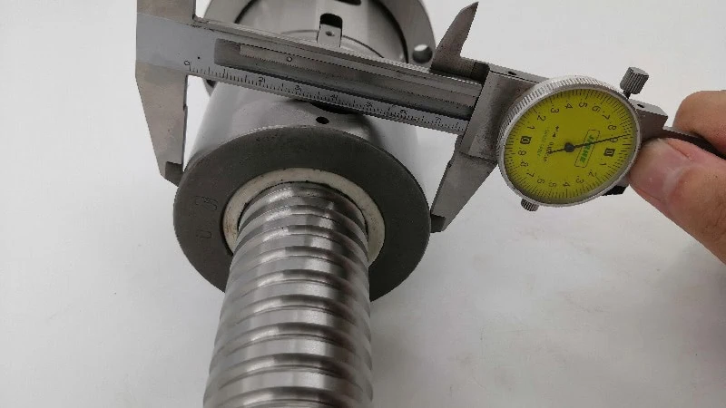
- Verify Straightness: This is perhaps the most important check. A ball screw must be perfectly straight to function correctly. You can check this by placing the screw on a flat reference surface, like a granite inspection table, and using a dial indicator to measure any runout as you roll it. Even a slight bend, invisible to the naked eye, can cause severe vibration and inaccuracy in the finished machine. It’s like trying to shoot an arrow that isn’t straight—it will never fly true.
- Test the Ball Nut: Before you make any cuts, slide the ball nut over the entire length of the screw thread. It should move smoothly and consistently from one end to the other. If you feel any tight spots or binding, it indicates a problem with either the screw or the nut that must be addressed. Discovering this after machining the ends is a costly and frustrating mistake.
How Should You Securely Clamp a Hardened Ball Screw?
How can you hold a delicate, hardened, and round object in a powerful lathe without crushing or damaging it? The answer lies in protecting the threads at all costs.
To securely clamp a hardened ball screw, you must never allow standard chuck jaws to touch the threads directly. Instead, you must use a protective split bushing or a collet system to distribute clamping pressure evenly. After clamping, you must perform a final alignment check with a dial indicator to ensure the screw runs true with minimal runout.
Why Standard Chuck Jaws Are a Bad Idea
Using the standard, hardened steel jaws of a lathe chuck to grip a ball screw thread is one of the fastest ways to destroy a very expensive component. It might seem like the most direct way to hold the part, but it causes several serious problems. Think about it: would you use a pair of serrated steel pliers to hold a delicate glass tube? Of course not. The same logic applies here.
Here is exactly why this method fails:
- It Destroys the Raceway: The “thread” on a ball screw is actually a precision-ground circular track called a raceway. This is the hardened path where the ball bearings roll. The sharp, hardened teeth of a standard chuck jaw will bite into this surface, creating permanent dents and high spots. When the ball nut later travels over this damaged area, it will cause rough movement, vibration, and catastrophic premature wear.
- It Provides a Poor Grip: A screw thread is a helix. Standard jaws can only make contact on the very top, or “crest,” of the threads. This means you have very little surface area contact, resulting in a weak and unstable grip. When you apply cutting forces, the screw is likely to vibrate or even shift in the chuck, making accurate machining impossible.
- It Creates Stress Points: The immense pressure concentrated on a few small points can create stress risers in the hardened steel. This can lead to the formation of micro-cracks that could eventually cause the screw end to fail under load.
Using a Bushing or Collet System for Protection
The professional solution is to create a protective barrier between the chuck jaws and the ball screw. This ensures the clamping force is distributed evenly without ever touching the critical raceway surfaces. The two best methods are using a split bushing or a collet system.
The Split Bushing Method
This is the most common and accessible method for job shops and maintenance departments. A split bushing is a simple, custom-made sleeve that wraps around the ball screw.
The process works like this:
- Create the Bushing: A piece of softer material, typically aluminum or brass, is machined. A hole is bored through its center that perfectly matches the outer diameter of the ball screw thread.
- Split the Bushing: The sleeve is then cut in half lengthwise, creating two C-shaped pieces.
- Clamp Securely: The two halves of the bushing are placed around the ball screw, and the lathe’s chuck jaws are then clamped onto the outside of the bushing.
This approach evenly distributes the clamping force across the entire circumference of the bushing, which in turn provides a firm, non-damaging grip on the ball screw threads.
The Collet System Method
For higher precision work or repetitive jobs, a collet system is a superior choice. A collet is a tapered sleeve that, when drawn into the lathe’s spindle, tightens to provide an exceptionally uniform grip around the workpiece. Because collets make 360-degree contact, they offer the best possible concentricity (how perfectly centered the part is) and rigidity. While requiring more specialized equipment, collets are the go-to choice for achieving the highest levels of accuracy in ball screw machining.
Proper Alignment and Runout Check
Simply clamping the screw is not enough. The final and most critical part of the setup is ensuring the screw is spinning perfectly in line with the lathe’s axis. Any wobble, known as runout, will be directly machined into your part, resulting in bearing journals that are not concentric with the screw’s raceway.
Here’s how to perform the alignment check:
| Step | Action |
|---|---|
| 1. Mount the Dial Indicator | Secure a sensitive dial test indicator to a magnetic base and place it on the lathe. Position the indicator’s stylus so it touches the outer diameter of the ball screw, near the chuck. |
| 2. Rotate and Measure | Slowly rotate the lathe chuck by hand one full revolution. As you turn it, watch the needle on the dial indicator. Any movement in the needle shows runout. |
| 3. Adjust for Zero Runout | Your goal is to get the needle to move as little as possible, ideally less than 0.0005 inches (or about 0.012 mm). If you see runout, gently tap the screw within the bushing/collet to adjust its position until it spins true. This step requires patience. |
| 4. Support the Opposite End | For any screw of significant length, you must use a live center in the lathe’s tailstock to support the free end. This prevents the screw from whipping or vibrating during the machining process, which is essential for both safety and accuracy. |
Only after the screw is securely clamped and spinning with virtually zero runout are you truly ready to make the first cut.
Which Tools and Machine Settings Are Required for Hard Turning?
What specialized tools and precise settings do you need to cut steel that’s already as hard as a file? This requires a specific combination of durable tooling and precise machine parameters.
For successful hard turning1 of a ball screw, you must use a Cubic Boron Nitride (CBN) insert2, not a standard carbide one. Additionally, you must apply the correct machine settings, which involve a high surface speed to generate heat at the cut and a low feed rate for precision, all while using high-pressure coolant to clear chips and maintain thermal stability.
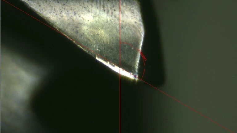
Choosing the Right Insert: CBN vs. Carbide
Machining a ball screw end is a process called “hard turning” because the steel has already been heat-treated to a high hardness (typically 58-64 on the Rockwell C scale3). Trying to cut this material with a standard tool is like trying to cut granite with a kitchen knife—it simply won’t work. Your choice of cutting tool insert is therefore the most important decision in this step.
The two main choices are Carbide and CBN. Let’s see how they compare.
| Tool Material | Best For | Performance on Hardened Steel (58+ HRC) | Why It Works (or Fails) |
|---|---|---|---|
| Carbide | General machining of soft steels, aluminum, plastics. | Fails immediately. The cutting edge will dull, chip, or break within seconds, producing a terrible surface finish and incorrect dimensions. | Carbide cannot withstand the extreme heat and abrasive forces generated when cutting hardened steel. The heat softens the cutting edge, making it useless. |
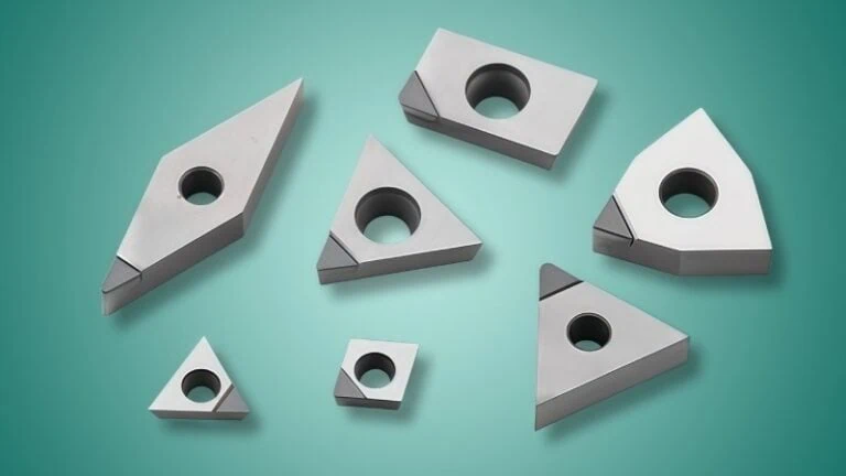
| CBN4 | Hard turning and machining abrasive materials. | Excellent. It cleanly cuts the hardened steel, producing a smooth, mirror-like surface finish and holding dimensional accuracy. | Cubic Boron Nitride (CBN) is the second-hardest material known to man, after diamond. It thrives in high heat and easily resists abrasion. |
Why CBN is the Only Real Choice
For hard turning, CBN is the required tool. Its unique ability to maintain its hardness at very high temperatures is what allows it to cut hardened steel effectively. While a carbide insert would melt and deform, a CBN insert uses the heat generated by the high cutting speed to its advantage, softening the steel workpiece at the exact point of the cut, which allows the material to be sheared away cleanly.
When selecting a CBN insert, it’s also important to consider its grade and geometry. Tooling manufacturers offer different grades of CBN for roughing or finishing, and specific geometries (like a negative rake angle) to give the cutting edge more strength. It is always best practice to consult your tooling supplier for a precise recommendation based on the ball screw’s material hardness.
Calculating Speeds and Feeds for Hardened Steel
Once you have the right tool, you need to use it correctly. “Speeds and feeds5” are the machine settings that control how fast the part spins and how quickly the tool moves. Getting these wrong can ruin the tool, the part, or both.
Think of it like this: speed is how fast the workpiece is moving past the tool (measured in Surface Feet per Minute, or SFM), and feed is how fast the tool advances along the workpiece (measured in Inches Per Revolution, or IPR).
For hard turning a ball screw with a CBN insert, the philosophy is high speed and low feed.
- High Cutting Speed: You’ll typically run the machine at a surface speed of 300 to 500 SFM. This high speed is what creates the intense, localized heat that softens the steel just ahead of the cutting tool, enabling the shearing action.
- Low Feed Rate: A very fine finishing feed rate of 0.001 to 0.003 IPR is used. This slow and steady advance ensures a beautiful surface finish and prevents putting too much pressure on the tool. You are essentially “skimming” the material with extreme precision.
- Shallow Depth of Cut: The depth of cut for a finishing pass is also very small, often just 0.005″ to 0.010″. You are removing only a tiny amount of material on the final pass to “sneak up” on the final dimension required by the bearing support drawing.
These parameters are excellent starting points, but the optimal settings can vary based on the specific machine’s rigidity and the CBN tool’s grade. Always use the tooling manufacturer’s provided data as your primary reference and adjust from there.
The Role of Coolant in Precision Machining
With all this talk of using heat to your advantage, should you just run the machine without any coolant? Absolutely not. While it may seem counterintuitive, coolant plays a critical role in precision hard turning, just not in the way you might think.
In standard machining, coolant’s main job is to keep the tool cool. Here, its job is different:
- Aggressive Chip Evacuation: The primary role of coolant in this process is to act as a high-pressure jet, blasting the small, razor-sharp chips away from the cutting area. If a hot chip were to get caught between the tool and the workpiece, or get wrapped around the part, it would instantly destroy the fine surface finish you are trying to create.
- Maintaining Thermal Stability: While the cutting edge needs to be hot, the entire ball screw needs to remain dimensionally stable. Flood coolant carries heat away from the overall workpiece, preventing it from expanding due to thermal growth. If the whole screw heats up and grows, the final dimensions you machine will be incorrect once it cools back down to room temperature. The goal is to keep the part cool while the tool does its hot work at the micro-level.
For these reasons, a steady stream of high-pressure coolant aimed directly at the tip of the tool is essential for achieving the dimensional accuracy and surface finish required for a perfect bearing fit.

What Is the Correct Sequence for Machining the Ends?
Now that the screw is clamped and you have the right tools, in what order should you actually perform the cuts? The answer is a methodical sequence where each step builds a foundation for the next.
The correct sequence for machining a ball screw end is a systematic, four-step process. You must first face the end and drill a center hole for support. Second, you turn the critical bearing journals to their final, precise diameters. Third, you cut the thread reliefs and the locknut threads. Finally, you perform a thorough deburring and a final quality check.
Step 1: Facing and Center Drilling
Before you can machine any precision features, you must establish a perfect foundation. This begins with two simple but non-negotiable operations.
- Facing the End: The very first cut is to “face” the end of the screw. This involves skimming a small amount of material off the end to create a surface that is perfectly flat and perpendicular to the axis of the screw’s rotation. This faced surface becomes your master reference, or “zero point,” for all the length dimensions that follow.
- Drilling a Center Hole: Immediately after facing, you must drill a small, cone-shaped hole precisely in the center of the new flat face. This isn’t for a bolt; its sole purpose is to create a locating point for the tailstock’s live center. This live center supports the free end of the screw, preventing it from whipping or vibrating during machining. A proper center hole ensures this support is rigid and perfectly on-axis, which is absolutely essential for achieving any level of accuracy.
Step 2: Turning the Bearing Journals
This is the most critical step of the entire process, where precision matters most. The bearing journals are the smooth, specific-sized diameters that the support bearings will be pressed onto. A mistake here will ruin the fit.
This process is a careful dance of cutting and measuring:
- Rough Turning: First, you’ll perform several “roughing” passes. Using your CBN insert, you will remove the bulk of the material quickly, turning the diameter down to just a little larger than the final required size. A common practice is to leave about 0.010″ to 0.015″ of material for the final pass.
- Finish Turning: This is the final, most important cut. As discussed in the previous section, this is a very slow, shallow pass (a low feed rate and a small depth of cut). This “finish pass” is what determines the final diameter and creates the smooth surface finish required for a proper bearing fit.
- Constant Measurement: Throughout this stage, the machinist will repeatedly stop the lathe to measure the journal’s diameter with a calibrated micrometer. They will cut a little, measure, and then carefully adjust for the next cut. This continues until the diameter is exactly within the tight tolerance specified on the drawing (often as small as ±0.0002 inches). The specific fit tolerance can vary, so it’s always wise to confirm the recommended shaft tolerances directly from the bearing manufacturer’s engineering data.
Step 3: Cutting the Thread Relief and Locknut Threads
With the precision journals complete, the next step is to machine the features that allow the bearings to be secured.
- Cutting the Thread Relief: A thread relief, or undercut, is a narrow groove machined at the base of the journal, right where it meets the shoulder. What is its purpose? Imagine trying to push a box perfectly flat against a wall that has a curve at the floor. The box will be held away from the wall by that curve. The thread relief is like cutting a small notch in the floor so the box can sit perfectly flush. It ensures the bearing makes full contact with the shoulder, which is critical for proper alignment and load handling.
- Threading for the Locknut: After the relief is cut, you will machine the threads for the locknut. Using a specialized threading tool, the machinist cuts the helical groove according to the specifications on the drawing (e.g., M20 x 1.0). During this process, they will use a thread gauge to check the fit, ensuring the actual locknut will screw on smoothly but without excessive play.
Step 4: Final Deburring and Quality Check
The machining is done, but the job isn’t finished. The final step is to ensure the part is perfect and ready for assembly.
| Final Process | What It Is | Why It’s Crucial |
|---|---|---|
| Deburring | The delicate, manual process of removing any tiny, sharp edges (burrs) left over from the machining operations. This is typically done with a fine file or a specialized deburring tool. | Burrs can act like tiny knives, scratching other components. More importantly, they can prevent the bearings from seating correctly or break off during operation, contaminating the lubricant and destroying the ball nut. |
| Quality Check | The final inspection where every critical dimension is measured one last time. This also involves a visual inspection of all surfaces and, most importantly, a physical test fit. | This is the ultimate confirmation of success. By sliding the actual bearing onto the journal and threading on the locknut, you can feel if the fit is perfect—not too tight, not too loose. It proves the job was done right. |
Conclusion
Machining a ball screw for a perfect fit is not about a single secret trick, but about the disciplined execution of a series of precise steps. From the initial inspection and careful reading of the drawing to the final deburring and test fit, each stage builds upon the last. By respecting the material’s hardness, protecting the delicate threads during clamping, using the correct CBN tooling, and following a logical machining sequence, you can consistently produce end features that meet the tight tolerances required for high-performance linear motion systems. Success lies in the details, and in this process, every detail matters.
References
- hard turning1 – An in-depth article from ZYDiamondTools explaining the process of hard turning and its advantages.
- Cubic Boron Nitride (CBN) insert2 – A product page from ZYDiamondTools detailing CBN inserts designed for machining hard materials.
- Rockwell C scale3 – Wikipedia article explaining the principles and application of the Rockwell hardness test.
- CBN4 – A comprehensive guide from ZYDiamondTools covering all aspects of CBN cutting tools.
- Speeds and feeds5 – A practical guide and interactive tool from ZYDiamondTools, explaining and calculating all essential machining parameters.