-
Whatsapp: +86 13526572721
-
Email: info@zydiamondtools.com
-
Address: AUX Industrial Park, Zhengzhou City, Henan Province, China
-
Whatsapp: +86 13526572721
-
Email: info@zydiamondtools.com
-
Address: AUX Industrial Park, Zhengzhou City, Henan Province, China

Why Is Your Tooling Wearing Out Prematurely? A Machinist’s Guide to Key Causes & Proven Solutions

Are you frustrated by CNC tools that dull, chip, or break long before they should, costing you critical time and money on the shop floor?
Premature tool wear is primarily caused by a combination of incorrect cutting parameters, poor heat management, using mismatched tool materials or coatings, and excessive system vibration. The most effective solutions involve mastering your speeds and feeds, selecting the right tool for the material, implementing a robust coolant strategy, ensuring a rigid machine setup, and leveraging modern toolpaths like High-Efficiency Milling (HEM).
What Are the Root Causes of Rapid Tool Wear?
Have you ever wondered why your expensive cutting tools are dulling or breaking far sooner than the manufacturer promised?
The primary causes of rapid tool wear are a combination of four critical factors: running the tool with incorrect speeds and feeds, allowing excessive heat to build up due to poor chip evacuation, using a tool material or coating that is mismatched for the job, and failing to control vibration caused by a lack of rigidity in the machine, tool holder, or workpiece setup.
Incorrect Speeds, Feeds, and Depth of Cut
Think of your machining parameters as a delicate balancing act. When this balance is off, your tool pays the price. Pushing a tool too hard or too slow is one of the fastest ways to destroy it, long before its natural lifespan is over.
- Cutting Speed (RPM): Running the spindle too fast generates immense friction, which creates excessive heat. This heat can soften the tool’s cutting edge, making it wear away quickly, a process known as thermal wear. Conversely, running too slowly can cause the workpiece material to stick and weld itself to the tool tip, creating what’s called a “built-up edge” (BUE), which can then break off and take a piece of the tool with it.
- Feed Rate (IPM / mm/min): The feed rate controls how fast the tool moves through the material. A feed rate that is too high puts extreme mechanical stress on the cutting edge, leading to chipping or even catastrophic fracture. However, a feed rate that is too low is just as damaging. Instead of shearing a clean chip, the tool begins to rub against the material, which polishes and dulls the edge through abrasion while generating unnecessary heat.
- Depth of Cut (DOC): This refers to how deep the tool engages with the material. Taking too aggressive a depth of cut increases cutting forces exponentially, overwhelming the tool’s structural integrity and leading to breakage.
It’s critical to remember that ideal parameters are not universal. Therefore, you should always start with the recommendations provided by your tooling supplier, as these values are specifically tested for their tools and can vary significantly based on the tool’s geometry and grade.
Ineffective Heat Management and Chip Evacuation
In machining, heat is the ultimate enemy. While some heat is an unavoidable byproduct of cutting, uncontrolled heat will destroy a tool faster than almost any other factor. This is where managing chips becomes vitally important.
Why are chips so important? Because they act as conveyors that carry heat away from the cutting zone. In fact, studies show that up to 80% of the heat generated during milling is carried away by the chip.
When chips are not cleared effectively, two destructive things happen:
- Heat Buildup: The chips remain in the cutting area, preventing coolant from reaching the tool tip and causing the localized temperature to skyrocket. This can soften the tool, degrade its coating, and accelerate wear.
- Chip Recutting: Trapped chips get cut a second or third time. This puts a sudden, unexpected load on the cutting edge, which is a very common cause of chipping and tool fracture. Imagine you’re cutting a carrot, and just as you press down, someone throws another piece of carrot under your knife—the sudden impact is jarring and uncontrolled. That’s what chip recutting does to your tool.
Mismatched Tool Material and Coating for Your Application
Premature tool failure is often rooted in a subtle but critical mismatch between the tool and the application. While coated solid carbide is the industry’s primary choice for its versatility and cost-effectiveness, its performance has limits. A mismatch occurs when carbide is tasked with a job that exceeds its physical or thermal capabilities, a scenario that calls for specialized superhard materials.
Substrate Mismatches: When Carbide Meets Its Limits
Understanding how carbide fails in extreme conditions reveals why PCD and CBN are necessary.
- Failure by Abrasion: When machining highly abrasive non-ferrous materials (like high-silicon aluminum or carbon fiber composites), the hard particles within the workpiece act like sandpaper, physically grinding away the carbide tool’s edge. Even the toughest carbide grades will wear down quickly. This specific failure mode is countered by the superior hardness of Polycrystalline Diamond (PCD).
- Failure by Heat: When machining hard ferrous materials (like hardened steel or chilled cast iron), the immense cutting forces generate extreme temperatures. This heat softens the cobalt binder in carbide, causing the tool edge to deform and fail rapidly. This is a thermal failure, which is solved by Cubic Boron Nitride (CBN), a material that retains its hardness at much higher temperatures.
Coating Mismatches: An Inadequate Shield
Coatings are designed to protect carbide, but they can also be a point of failure. A mismatch can be as simple as using a general-purpose TiN coating on a high-temperature alloy that requires a heat-resistant AlTiN coating. More importantly, even the best coating is only a thin layer. In applications with extreme abrasion or heat, the coating wears away quickly, exposing the less-capable carbide substrate to conditions it cannot handle. This is where relying on the inherent properties of a PCD or CBN substrate, rather than just a coating, becomes the correct engineering solution.
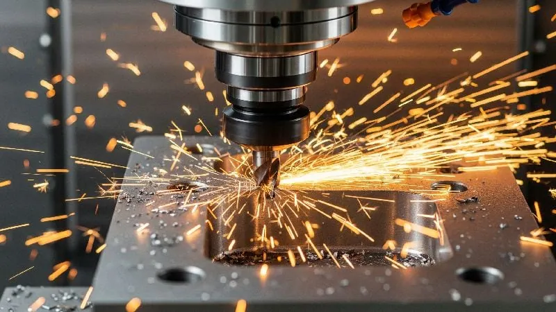
Excessive Vibration and Lack of System Rigidity
Vibration, often heard as a high-pitched “squeal” called chatter, is a tool killer. It creates microscopic impacts on the cutting edge, thousands of times per minute. While a single impact is tiny, their cumulative effect is devastating, leading to micro-chipping that quickly grows into a major tool failure.
Think of it like trying to write with a pencil while someone is shaking your hand. The result is messy and the pencil tip (the cutting edge) is likely to break.
Vibration is rarely caused by just one thing. It’s a problem with the entire system’s rigidity, which includes:
- The Machine: Worn spindle bearings or loose components can introduce chatter.
- The Tool Holder: An unbalanced holder, insufficient clamping pressure, or simply using a tool holder that is too long will amplify vibration. As a rule of thumb, for every diameter you increase the tool’s overhang (stick-out), you reduce its rigidity by a factor of eight.
- The Workpiece: Thin-walled parts or workpieces that are not securely clamped to the machine table are prime sources of vibration.
How to Visually Identify Critical Wear Patterns
A worn tool tells a story. By learning to “read” the wear patterns, you can accurately diagnose the root cause of the failure and prevent it from happening again. It’s the most direct feedback you can get from your process.
| Wear Pattern | What it Looks Like | What it’s Telling You |
|---|---|---|
| Flank Wear | A uniform, flat “land” worn onto the side (flank) of the cutting edge. | This is normal abrasive wear, but if it happens too fast, your cutting speed is likely too high, generating excess heat and abrasion. |
| Crater Wear | A bowl-shaped “crater” or cavity worn into the top face of the tool where the chip flows. | This is caused by a chemical reaction between the hot chip and the tool face. It’s common in steels and indicates heat is too high, possibly due to high speed or insufficient cooling. |
| Chipping | Small, random pieces broken off the cutting edge. | This is a clear sign of impact. The cause is often mechanical overload from a feed rate that is too high, vibration (chatter), or chip recutting. |
| Built-Up Edge (BUE) | A lump of workpiece material welded onto the tool’s cutting edge. | This happens when friction and pressure are high but the temperature isn’t high enough for a clean shear. It’s a sign that your cutting speed is too low, common in soft materials like aluminum. Increasing speed often solves it. |
What Proven Strategies Will Extend Your Tool Life?
Now that you can identify what’s destroying your tools, how can you effectively fight back and get the most value from every single one?
To dramatically extend tool life, you must master your cutting parameters for optimal chip load, meticulously select the correct tool and coating for your specific material, implement a robust coolant and chip evacuation plan, maximize rigidity by securing your setup, and leverage modern, intelligent toolpaths like High-Efficiency Milling (HEM).
Mastering Your Cutting Parameters for Optimal Performance
Setting the right parameters is about finding the “sweet spot” for your tool. It’s not about raw speed; it’s about control and efficiency. The goal is to maintain an ideal chip load—the thickness of the material that each cutting edge (flute) shears away.
Why is chip load so important? A correct chip load ensures the tool is cutting, not rubbing. It creates a clean shearing action that efficiently removes material and heat. An incorrect chip load, whether too thick or too thin, leads directly to the wear patterns we discussed earlier.
So, how do you find that sweet spot? 🎯
- Start with the Source: Always begin with the cutting parameter recommendations from your tool’s manufacturer. They provide a tested starting point for Surface Feet per Minute (SFM) and Chip Load Per Tooth (CLPT) for various materials.
- Calculate, Don’t Guess: Use these values to calculate your starting RPM and Feed Rate1.
RPM = (SFM * 3.82) / Tool DiameterFeed Rate (IPM) = RPM * CLPT * Number of Flutes
- Observe and Adjust: Pay attention to the cut. Listen for chatter and look at the chips. For steels, light straw-colored or golden chips are often a sign of a healthy cut. Dark blue or black chips mean you have excessive heat and your SFM is likely too high. Adjust one variable at a time in small increments (5-10%) until the cut is stable and efficient.
Remember, the published data is a starting point. Your specific machine rigidity and setup will require fine-tuning, so always approach new setups with a plan to optimize.
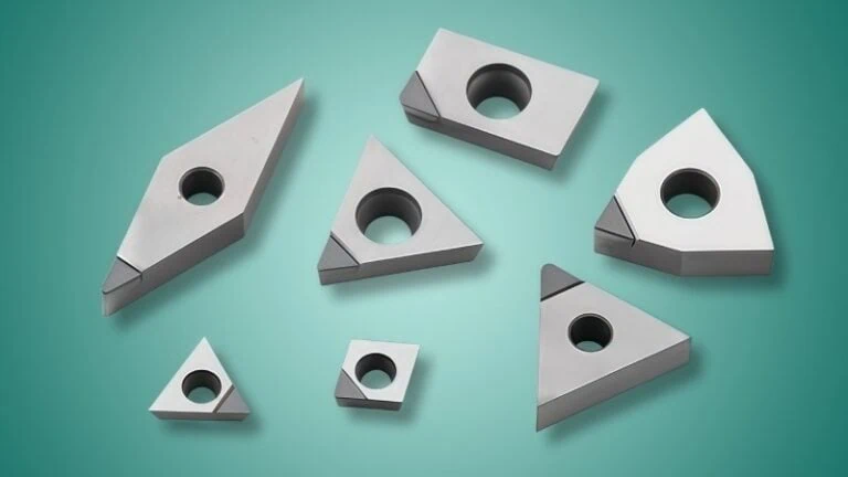
Selecting the Right Tool and Coating for the Material
Choosing a tool is a strategic decision. The solution is to match the tool material to the workpiece material with precision, starting with the industry standard and moving to specialized tools only when necessary.
The Standard Choice: Coated Carbide
For the vast majority of machining jobs—including most steels, stainless steels, and standard aluminum alloys—a coated solid carbide tool is the correct and most cost-effective choice. The decision here is less about the substrate and more about selecting the optimal grade and coating. For example, an AlTiN coating is excellent for resisting heat when machining stainless steel, while a ZrN or DLC coating provides the necessary slickness for machining aluminum without material buildup. Optimizing your carbide selection is the first and most important step.
The Specialist Choice: Solving Specific Challenges with PCD & CBN
If you have optimized your carbide tool and still face rapid wear on a specific “problem material,” it is time to consider a superhard tool2. The selection is based on a clear division of material types:
- For Abrasive, Non-Ferrous Materials, Select PCD: Polycrystalline Diamond is the definitive solution for materials that act like sandpaper.
- Applications: High-silicon aluminum, carbon and glass fiber composites (CFRP/GFRP), graphite, metal matrix composites (MMCs), and green ceramics.
- Why it Works: The extreme hardness of diamond resists abrasion far beyond any carbide or coating. In applications like milling abrasive aluminum alloys, a PCD tool can extend tool life by 50-100x over carbide, maintaining consistent part quality and reducing downtime. PCD is typically used uncoated.
- For Hard, Ferrous Materials, Select CBN: Cubic Boron Nitride is the solution for materials that are too hard or generate too much heat for carbide.
- Applications: Hardened steels (45-70 HRC), tool steels, chilled and high-chrome cast irons, and nickel/cobalt-based superalloys.
- Why it Works: CBN’s key advantage is its thermal stability. It stays hard at temperatures where carbide deforms, allowing for “hard turning” or “hard milling,” processes that can replace slower, more expensive grinding operations. The choice here is often about the CBN grade (e.g., high CBN content for roughing cast iron, low CBN content for finishing hardened steel).
By starting with a deep understanding of carbide and its coatings, and then knowing precisely when to deploy PCD or CBN, you create a robust, efficient, and economically sound machining strategy.
Implementing an Effective Coolant and Lubrication Plan
Coolant does more than just cool; it’s a critical part of your process that flushes away chips, reduces friction, and prevents thermal shock. However, simply turning on the flood coolant isn’t enough. You need to ensure it’s doing its job effectively.
Optimizing Your Coolant Delivery
- Flood Coolant: This is the most common method. The key is nozzle position. You must aim the coolant streams directly at the point of the cut. If the nozzle is aimed at the body of the tool, the coolant may never reach the cutting edge where all the heat is being generated.
- Through-Spindle Coolant (TSC): This is a game-changer for drilling and deep pocketing. Coolant is forced at high pressure through channels inside the tool itself, emerging directly at the cutting tip. This guarantees lubrication and forcefully blasts chips out of the way, preventing the dreaded chip recutting. A machine with TSC can often run drills and end mills at significantly higher parameters than one without.
- Air Blast / MQL: For materials like aluminum, where chip evacuation is more critical than cooling, a strong blast of compressed air can be more effective than flood coolant. It keeps the cutting area clear without the mess. Minimum Quantity Lubrication (MQL) pairs this air blast with a tiny amount of oil mist for lubrication.
Securing Your Workholding and Machine Setup
You can have the best tool and perfect parameters, but if your setup is not rigid, you will have vibration. Vibration is the enemy of tool life and surface finish. Securing your setup is one of the most impactful and low-cost things you can do to improve performance.
Here’s where to focus:
- Minimize Tool Overhang: This is the golden rule of rigidity. The further a tool “sticks out” from the holder, the more it will vibrate. Always use the shortest tool and tool holder possible for the job. If you must use a long tool, reduce your cutting parameters accordingly.
- Use High-Quality Workholding: A cheap vise or worn clamps will not hold the workpiece securely. Ensure your vise is torqued down properly and that the workpiece is held firmly, with as much surface area contact as possible. For thin parts, use supports to prevent flexing.
- Maintain Your Holders and Spindle: Before loading a tool, wipe the taper on the tool holder and the inside of the machine spindle. Even a tiny chip or piece of debris can cause the tool to run out of true (wobble), creating imbalance and vibration.
Leveraging High-Efficiency Milling (HEM) Toolpaths
High-Efficiency Milling (HEM) is a modern machining strategy that is radically different from traditional methods—and it’s designed specifically to maximize tool life. It’s a smarter way to work, not a harder one.
Instead of taking a wide, slow, and heavy cut, HEM uses a very different philosophy:
- Low Radial Depth of Cut (RDOC): It engages only a small portion of the tool’s diameter (e.g., 5-15%).
- High Axial Depth of Cut (ADOC): It uses a much deeper portion of the flute length, often the full length.
- High Feed Rate: The feed rate is dramatically increased.
This combination creates a thin, manageable chip and keeps the tool in constant, predictable motion. The results are astounding.
Industry Case Study: In a test machining 4140 alloy steel, a traditional slotting toolpath resulted in a tool life of approximately 25 minutes. By switching to an HEM toolpath with the exact same tool, the tool life increased from 25 minutes to over 90 minutes—an improvement of more than 260%—while also reducing the overall cycle time.
The magic of HEM is that it spreads the work over a larger portion of the cutting edge, preventing any single point from overheating or overloading. This consistent, light engagement is the ultimate strategy for combating wear and getting the most out of modern cutting tools.
Conclusion
Ultimately, combating premature tool wear is not about finding a single secret trick. It is a systematic process of controlling key variables. By first understanding the fundamental causes—from heat and vibration to mismatched parameters—you can then strategically apply the right solutions. Mastering your setup, choosing tools with intention, and leveraging modern strategies like HEM will transform your tools from a consumable expense into a predictable, reliable, and highly profitable asset. This proactive approach leads to lower costs, higher quality parts, and a more efficient and competitive machine shop.
References
- Calculate your starting RPM and Feed Rate1 – The ZYDiamondTools Speeds & Feeds Calculator, a practical tool to determine optimal cutting parameters for various materials and tools.
- Superhard tool2 – The ZYDiamondTools product category page for PCD & PCBN tools, showcasing a range of solutions for demanding applications.