-
Whatsapp: +86 13526572721
-
Email: info@zydiamondtools.com
-
Address: AUX Industrial Park, Zhengzhou City, Henan Province, China
-
Whatsapp: +86 13526572721
-
Email: info@zydiamondtools.com
-
Address: AUX Industrial Park, Zhengzhou City, Henan Province, China

PCD Fly Cutters Explained: Are They Right for Your Application and Budget?

Considering PCD fly cutters for your machining operations and wondering if they are genuinely the right choice for your specific applications and overall budget?
PCD (Polycrystalline Diamond) fly cutters are high-performance tools ideal for machining non-ferrous metals and abrasive non-metallic materials, offering significant advantages in tool life, speed, and surface finish. While they have a higher initial cost, their suitability depends on balancing these benefits against your application’s demands and production volume to achieve long-term cost-effectiveness and a strong return on investment.
What Defines a PCD Fly Cutter and Its Machining Principle?
So, you might be wondering, what exactly is a PCD fly cutter and how does it achieve its cutting action?
A PCD fly cutter is a specialized cutting tool featuring one or more cutting edges made from Polycrystalline Diamond (PCD) material1, designed primarily for high-speed precision machining of flat surfaces, particularly on non-ferrous materials and abrasive non-metallics. Its machining principle relies on the PCD edge(s) rotating at high speeds to shave or ‘fly cut’ material, producing excellent surface finishes and maintaining accuracy over long production runs due to PCD’s exceptional hardness and wear resistance.
To truly understand these tools, let’s delve deeper into their core aspects.
Understanding Polycrystalline Diamond (PCD) Material
Polycrystalline Diamond, or PCD as it’s commonly known in the industry, is not your typical diamond. Instead, it’s a remarkable synthetic material. Imagine taking many tiny, man-made diamond particles and fusing them together with a metallic binder, usually cobalt, under extremely high pressure and intense heat through a process known as sintering2. The result? An exceptionally hard and wear-resistant polycrystalline3 composite material, perfect for cutting tools.
Now, why is this hardness so important?
PCD is significantly harder than conventional cutting tool materials like tungsten carbide or High-Speed Steel (HSS). This superior hardness means that cutting tools made with PCD can machine tough and abrasive materials for much longer periods before showing signs of wear. For instance, in high-volume aluminum machining, PCD tools can often outlast carbide tools by a factor of 50 to 100 times, or even more, depending on the specific application and material.
Beyond its impressive hardness, PCD offers other beneficial properties for cutting:
- High Wear Resistance: Directly resulting from its hardness, this allows the cutting edge to stay sharp for extended periods.
- Good Thermal Conductivity: PCD can efficiently draw heat away from the cutting zone. This is crucial in high-speed machining as it helps protect both the tool and the workpiece from heat-related damage. However, it’s worth noting that PCD is generally not recommended for machining ferrous materials (like steel or cast iron) at high speeds due to a chemical reaction that can occur between carbon in the PCD and iron at elevated temperatures, leading to accelerated wear.
- Low Friction: PCD surfaces are quite slick, meaning less friction as the tool cuts through the material. This can lead to better surface finishes and reduced cutting forces.
In essence, PCD was developed to provide a cutting tool material that offers performance characteristics approaching those of natural diamond but with greater toughness and availability for industrial applications.
The Fly Cutting Concept: Single-Point or Multi-Point Machining
The term “fly cutting” refers to a specific machining process where a rotating cutting tool, typically with one or more cutting edges, is used to generate a flat surface on a workpiece. The tool spins, and its cutting edge(s) sweep across the material. This action shaves off material to create the desired flat plane.
There are primarily two ways this concept is applied in PCD fly cutters:
Single-Point Fly Cutting
Traditionally, fly cutting often involved a tool with just a single cutting point or insert. In this setup, that lone cutting edge does all the material removal in a single pass or revolution.
- How it works: The single PCD tip rotates and is fed across the workpiece. Because only one edge is cutting, it’s possible to achieve extremely fine surface finishes and high precision.
- Common uses: Single-point fly cutting is often favored in applications requiring exceptionally smooth surfaces or when tool balancing for very high RPMs is critical. For example, in creating precision scientific instrument components or in some custom engine rebuilding scenarios to achieve a perfectly flat cylinder head surface.
Multi-Point Fly Cutting
Modern PCD fly cutters, especially those used in production environments, typically feature multiple PCD inserts or cutting edges. These can range from two inserts up to a dozen or more on larger tools.
- How it works: Each PCD insert around the cutter body takes a small cut as the tool rotates. This collective effort allows for much faster material removal rates compared to single-point tools while still maintaining excellent surface quality thanks to the properties of PCD.
- Common uses: This is the go-to method for high-volume manufacturing. For instance, automotive plants might use multi-insert PCD fly cutters for face milling aluminum engine blocks or transmission casings, where both the speed of machining and the quality of the finished surface are vital for subsequent assembly and performance. A fly cutter with 6 PCD inserts, for example, can machine a large aluminum casting much faster than a single-point tool could.
Regardless of whether it’s single-point or multi-point, the fundamental principle is the same: the precise, sweeping action of the hard PCD edge(s) across the workpiece generates the flat surface.
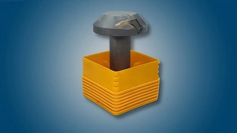
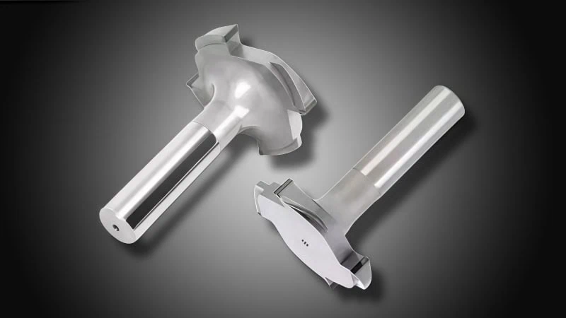
Key Components of a Typical PCD Fly Cutter
A PCD fly cutter, while a precision instrument, is made up of several key components working together. Understanding these can help appreciate how the tool functions:
- Cutter Body: This is the main structure or backbone of the fly cutter. It’s typically precision-machined from materials like hardened steel for rigidity and durability, or sometimes high-strength aluminum alloys. Aluminum bodies are often preferred for very high-speed applications due to their lower weight, which reduces rotational mass and stress on the machine spindle. The choice of body material can vary between suppliers and is often dictated by the tool’s diameter, intended rotational speed, and the machining application, so discussing these aspects with your tool provider can be beneficial.
- PCD Inserts/Tips/Blades: These are the actual cutting elements and the heart of the tool. Each insert is a small piece of PCD material, often brazed (a high-temperature soldering process) onto a carbide substrate for support. These PCD-tipped inserts are then mounted onto the cutter body. In many designs, especially for larger production tools, these inserts are replaceable, meaning if one gets damaged or worn, you don’t have to replace the entire cutter body.
- Insert Pockets or Cartridges/Cassettes: The cutter body has precisely machined pockets or seats where the PCD inserts (or cartridges holding the inserts) are located.
- Direct Seating: Some simpler designs might have inserts brazed directly to the body or seated in fixed pockets.
- Cartridges/Cassettes: More advanced fly cutters, particularly larger ones or those designed for ultra-fine adjustments, use cartridges or cassettes. Each PCD insert is mounted on one of these adjustable units. This allows for very precise setting of each cutting edge in terms of height (axial position) and sometimes radial position, which is critical for achieving the best possible surface finish and ensuring all inserts share the cutting load evenly. The specific design and adjustability features of these holding mechanisms can differ significantly between tool manufacturers, so referring to the supplier’s documentation for specific details on setting and adjustment is recommended.
- Clamping Mechanism: For designs with replaceable inserts or cartridges, a secure clamping mechanism is essential. This usually involves high-tensile screws or wedges that hold the insert or cartridge firmly in place against the cutting forces. A robust and precise clamping system is vital for safety, accuracy, and tool life.
- Shank or Arbor Mounting Interface: This is the part of the cutter body that connects the fly cutter to the machine tool’s spindle. Common types include:
- Cylindrical shanks (for smaller fly cutters, often held in collet chucks or end mill holders).
- Shell mill arbors (where the cutter has a central bore and is mounted onto a machine arbor).
- Integrated shank systems like HSK, BT, CAT, or CAPTO interfaces for direct mounting into high-performance machine spindles.
- It’s absolutely critical that the mounting interface of the fly cutter matches the machine spindle or tooling system. Using incorrect or incompatible mounting can lead to poor performance, damage to the tool or machine, and serious safety hazards. Always verify compatibility with your machine tool specifications and the tool supplier.
For example, a large PCD fly cutter designed for finishing aluminum alloy automotive transmission housings might feature alightweight aluminum body (perhaps 250mm in diameter), 8 adjustable cartridges each holding a PCD insert, and an HSK-A100 shank for secure mounting in a high-speed machining center. Each component is engineered to contribute to the tool’s overall performance in terms of speed, precision, and longevity.
Which Materials and Operations See the Greatest Benefit from PCD Fly Cutters?
So, where do PCD fly cutters truly shine, and for what kinds of jobs are they the best choice?
PCD fly cutters deliver their greatest benefits when machining non-ferrous metals like aluminum4 and its alloys, copper, and brass, as well as highly abrasive non-metallic materials such as composites, laminates, and certain ceramics (in their pre-sintered or ‘green’ state). They are exceptionally well-suited for high-speed surface finishing operations aiming for excellent, sometimes mirror-like, finishes, making them invaluable in industries like automotive, aerospace, and woodworking.
Let’s explore these areas in more detail to understand why PCD is the preferred choice.
Excelling in Non-Ferrous Metals (Aluminum, Copper, Brass Alloys)
PCD fly cutters are champions when it comes to machining non-ferrous metals. But why is that? Firstly, PCD has a low chemical affinity with these metals. This means the PCD material doesn’t readily react with metals like aluminum or copper, even at the high temperatures generated during cutting. This is a key difference compared to machining steels, where PCD can experience higher chemical wear. Secondly, PCD’s extreme hardness allows it to easily cut through these often softer (but sometimes abrasive) materials, maintaining a sharp cutting edge for a very long time and preventing a common issue called “built-up edge” (BUE), where material from the workpiece welds itself to the tool tip.
- Aluminum and Its Alloys: This is perhaps the most common application area.
- High-Silicon Aluminum: Alloys containing high percentages of silicon (e.g., A356, A390, often used in automotive engine blocks, pistons, and pump housings) are notoriously abrasive. Standard carbide tools can wear out very quickly when machining these. PCD, however, thrives in this environment. For instance, in machining the deck face of a high-silicon aluminum engine block, a PCD fly cutter might last for tens of thousands, or even hundreds of thousands, of parts, whereas a carbide cutter might only last for a few hundred or a couple of thousand. This drastic difference in tool life leads to massive productivity gains.
- General Aluminum Alloys: For aerospace components, architectural elements, or consumer electronics casings made from common aluminum grades (like 6061 or 7075), PCD provides fast cutting and excellent surface finishes.
- Copper and Brass Alloys:
- Copper: Pure copper and its alloys are used for their high electrical and thermal conductivity (e.g., busbars, heat sinks, electrical connectors). PCD fly cutters can machine these materials efficiently, producing clean cuts without significant smearing, which is important for maintaining the material’s functional properties.
- Brass Alloys: Used for fittings, valves, and decorative components, brass machines well with PCD, allowing for good surface finishes and dimensional accuracy.
Superior Performance on Abrasive Composites and Laminates
Many modern materials, especially composites and laminates, are incredibly tough and abrasive. They can act like sandpaper on cutting tools, causing rapid wear. This is where PCD fly cutters truly demonstrate their superior wear resistance.
- Carbon Fiber Reinforced Polymers (CFRPs): These materials are prized in aerospace and high-performance automotive applications for their high strength-to-weight ratio. However, the carbon fibers are extremely abrasive. PCD fly cutters can machine CFRPs effectively5, producing clean edges with minimal delamination (separation of layers) or fiber pull-out. For example, trimming the edges of a CFRP aircraft wing skin or an automotive chassis component.
- Glass Fiber Reinforced Polymers (GFRPs): Commonly known as fiberglass, GFRPs are used in boat hulls, wind turbine blades, and various industrial components. Like CFRPs, they are very abrasive. PCD tooling extends tool life dramatically in these applications.
- Metal Matrix Composites (MMCs): These are advanced materials, such as aluminum reinforced with silicon carbide particles. MMCs are exceptionally abrasive and difficult to machine. PCD is often one of the only viable cutting tool materials for achieving reasonable tool life and productivity when machining MMCs, for components like specialized brake rotors or high-performance engine parts.
- Wood Laminates and Advanced Wood Composites: In the woodworking and furniture industries, materials like High-Pressure Laminates (HPL), Laminated Veneer Lumber (LVL), Medium-Density Fiberboard (MDF), and particleboard are common. These often contain abrasive resins, glues, and fillers that quickly dull conventional carbide tools. PCD fly cutters offer substantially longer operational times when surfacing or sizing these engineered wood products.
Ideal for High-Speed Surface Finishing and Mirror Finishes
When the goal is an exceptionally smooth, flat surface, especially on non-ferrous metals, PCD fly cutters are often the go-to solution, particularly in high-speed machining (HSM)6 environments.
- Achieving Mirror Finishes: Due to PCD’s ability to be honed to an extremely sharp and durable cutting edge, coupled with its low friction properties, it can produce “mirror finishes” on materials like aluminum. Surface roughness values (Ra7) can often be achieved well below 0.1 micrometers (µm) with properly configured PCD fly cutters and stable machining conditions. This level of finish might be required for:
- Molds for plastic injection or optical components.
- Decorative automotive or architectural trim.
- Precision surfaces on scientific instruments.
- High-Speed Machining (HSM) Advantages: PCD is well-suited to the demands of HSM. Its ability to maintain edge integrity at high rotational speeds allows for significantly increased cutting speeds and feed rates compared to carbide. For instance, when face milling aluminum, PCD fly cutters can often run at cutting speeds of 1,000 to 3,000 meters per minute (m/min), and sometimes even higher. In contrast, carbide tools might be limited to a few hundred m/min for similar operations if long tool life is desired. Achievable cutting speeds and feeds are highly dependent on the specific PCD grade, the machine tool’s capability (spindle speed, rigidity, accuracy), the workpiece material, and the tool’s balance and clamping. It’s advisable to start with supplier recommendations and optimize from there.
A practical benefit is that a very flat and smooth sealing surface on an aluminum component, for example, can often be achieved in a single high-speed pass with a PCD fly cutter. This can eliminate the need for secondary operations like grinding or lapping, saving considerable time and cost in production.
Common Industry Use Cases: Automotive, Aerospace, Woodworking
The benefits we’ve discussed translate into widespread use across several key industries:
- Automotive Industry: This is a major user of PCD fly cutters due to the high volumes of aluminum components.
- Engine Components: Machining engine block deck faces, cylinder head faces (combustion, intake/exhaust manifold surfaces), timing chain covers, and oil sumps.
- Transmission Parts: Finishing transmission casings, valve bodies, and differential housings.
- Other Parts: Machining aluminum wheels, pistons, turbocharger components, and brake system parts.
- Industry Impact Example: A typical automotive plant producing aluminum engine components might see a reduction in machine downtime for tool changes by over 90% when switching from carbide to PCD fly cutters for a critical surfacing operation, directly boosting output and lowering cost per part.
- Aerospace Industry: Precision, reliability, and the machining of lightweight, high-strength materials are paramount here.
- Structural Components: Milling aluminum alloy wing spars, ribs, fuselage stringers, and window frames.
- Composite Machining: Trimming and surfacing CFRP and GFRP aircraft interior panels, control surfaces, and fairings.
- Engine and System Components: Manufacturing parts for turbines, landing gear, and various hydraulic and fuel system components from non-ferrous alloys.
- Woodworking and Furniture Industry: Particularly for engineered wood products and high-volume production.
- Panel Processing: Sizing and surfacing MDF, HDF, particleboard, and plywood panels.
- Laminated Products: Machining laminated flooring, kitchen countertops, and cabinet components made from HPL or melamine-faced boards.
- Solid Wood (Certain Applications): While not always the first choice for all solid woods, PCD can be beneficial for highly abrasive or resinous hardwoods in long production runs.
While these three are major areas, PCD fly cutters also find applications in other sectors like electronics (for aluminum heat sinks and enclosures), manufacturing of medical devices, and general engineering where high-volume, precision machining of non-ferrous and abrasive materials is required.
What Are the Decisive Performance Advantages of Upgrading to PCD Fly Cutters?
So, what are the real game-changing benefits when you switch to using PCD fly cutters?
Upgrading to PCD fly cutters offers several decisive performance advantages, most notably a dramatic increase in tool life and durability, the ability to operate at significantly higher cutting speeds and feed rates, the achievement of superior surface finishes, and consequently, a substantial boost in overall productivity coupled with reduced machine downtime.
Let’s break down each of these advantages to see how they can transform your machining operations.
Significantly Extended Tool Life and Durability
One of the most striking benefits of PCD fly cutters is their incredible lifespan. Thanks to the extreme hardness and wear resistance of Polycrystalline Diamond, these tools can last dramatically longer than their carbide8 or high-speed steel counterparts, especially in the right applications.
The analogy of a pencil needing frequent sharpening versus a specialized stylus that maintains its point for an incredibly long time is quite fitting for comparing regular tools to PCD.
- How much longer? While it varies greatly with the material being cut, the machine, and the cutting conditions, it’s not uncommon for PCD fly cutters to last 25 to 100 times longer than carbide tools, and in some cases, the difference can be even more staggering. For example, when machining highly abrasive high-silicon aluminum, a carbide tool might machine a few hundred to a couple of thousand parts. A PCD fly cutter in the same operation could potentially machine tens of thousands, or even over a hundred thousand, parts before needing replacement or re-lapping of the PCD tips.
- What this means for you:
- Fewer tool changes: This is a direct and obvious benefit.
- Consistent performance: Because the PCD edge degrades so slowly, the cutting performance remains consistent for much longer, leading to more uniform parts.
- Greater process reliability: There’s less worry about a tool wearing out unexpectedly mid-cut on a critical component.
Industry Example: In woodworking, when machining abrasive materials like Medium Density Fiberboard (MDF) or laminated particleboard, a set of carbide cutters might need resharpening after processing several hundred boards. A PCD fly cutter, on the other hand, could potentially process many thousands of boards, sometimes lasting for months in high-production settings before requiring service. Of course, the exact increase in tool life will depend on factors such as the specific grade of PCD, the material’s abrasiveness, cutting parameters, and the condition of the machinery. Consulting with your tooling supplier for realistic expectations in your specific scenario is always best.
Capability for Higher Cutting Speeds and Feed Rates
PCD doesn’t just last longer; it also allows you to machine faster – much faster, in many cases. This is due to PCD’s ability to maintain its hardness and sharp cutting edge even at the higher temperatures generated during high-speed machining (especially with non-ferrous materials) and its excellent thermal conductivity, which helps dissipate heat.
PCD fly cutters can be likened to race cars compared to regular streetcars when it comes to machining suitable materials. They operate at significantly higher cutting speeds and feed rates.
* Cutting Speed Comparison: For instance, when face milling aluminum, PCD tools can often run optimally at cutting speeds ranging from 1,000 to 3,000 meters per minute (m/min), and sometimes even higher in specialized applications. Traditional carbide tools might be limited to speeds of 300 to 800 m/min in similar aluminum applications if a reasonable tool life is to be maintained.
* Impact on Cycle Time: This ability to cut faster directly reduces the time it takes to machine each part. If an operation took 60 seconds with a carbide tool, it might only take 20-30 seconds with an optimized PCD setup. Over thousands of parts, these seconds add up to massive time savings.
What this means for you:
* Shorter cycle times: Produce more parts in the same amount of time.
* Increased machine capacity: If your machines are running faster, you might be able to take on more work without needing more machines.
It is crucial to remember that achieving these higher speeds and feeds requires a capable machine tool that is rigid, well-maintained, and has a spindle designed for such speeds. Furthermore, tool balancing becomes very important at higher RPMs. Referring to the cutting parameters recommended by your PCD tool supplier as a starting point and optimizing carefully is advisable.
Achieving Superior Surface Finish Quality
Beyond just cutting faster and lasting longer, PCD fly cutters are renowned for the exceptional surface finishes they can produce. If you need a part to be very smooth, perhaps even reflective, PCD is often the answer.
- Why the better finish?
- Ultra-sharp edges: PCD can be ground and lapped to an incredibly sharp and smooth cutting edge.
- Edge retention: Because PCD is so wear-resistant, it maintains this sharp edge for a very long time, leading to consistent finishes part after part.
- Low friction: PCD has a low coefficient of friction, meaning the material being cut is less likely to stick to the tool (a problem known as built-up edge or BUE). Less sticking means a cleaner cut and a smoother surface.
- The result:
- “Mirror finishes”: Particularly on non-ferrous metals like aluminum or copper alloys, PCD fly cutters can often produce what’s described as a “mirror finish,” with surface roughness (Ra) values sometimes well below 0.1 micrometers.
- Reduced secondary operations: Often, the finish achieved with a PCD fly cutter is so good that it can eliminate the need for later finishing processes like grinding, lapping, or polishing. This saves additional time, labor, and cost.
Industry Example: Consider the manufacturing of molds for clear plastic components, like an automotive headlamp lens. The surface finish of the aluminum mold cavity must be nearly perfect to ensure the plastic lens comes out optically clear. PCD fly cutters are often used to machine these mold surfaces, achieving a level of smoothness that requires minimal, if any, subsequent hand polishing.
Impact on Overall Productivity and Reduced Downtime
When you combine significantly longer tool life, faster cutting capabilities, and superior finishes that reduce rework, the overall impact on your manufacturing operation is a substantial boost in productivity and a welcome reduction in costly downtime.
- More Uptime, Less Downtime: This is a simple but powerful equation.
- Drastically fewer tool changes: As highlighted, if a PCD tool lasts 50 times longer than a carbide one, that’s 49 tool changes you don’t have to make. Each tool change means the machine is stopped, not making parts.
- Consider this: In a high-volume automotive line producing, say, 1,000 aluminum transmission casings per day, if a carbide tool set needs changing after every 200 parts, that’s 5 tool changes per day. If each change takes 20 minutes (including stopping, changing, resetting), that’s 100 minutes of lost production time daily. A PCD tool set that lasts for 20,000 parts might run for 20 days without a change due to wear, almost eliminating this specific cause of downtime.
- Increased throughput: Faster cycle times mean more parts are completed per hour, per shift, and per day.
- Drastically fewer tool changes: As highlighted, if a PCD tool lasts 50 times longer than a carbide one, that’s 49 tool changes you don’t have to make. Each tool change means the machine is stopped, not making parts.
- Improved Process Stability and Efficiency:
- Consistent quality: With tools that maintain their edge and performance for extended periods, part quality becomes more consistent, reducing scrap and rework rates.
- Lower cost per part: While PCD fly cutters typically have a higher initial purchase price than carbide tools, their extended life, the reduction in downtime, and the increased machining speeds often result in a significantly lower total cost to produce each part. These performance advantages are the primary drivers of that cost efficiency, an aspect we’ll explore more in the context of investment value.
In essence, upgrading to PCD fly cutters in the right applications isn’t just about getting a better tool; it’s about optimizing your entire machining process for greater efficiency, higher output, and improved quality.
How Do You Select the Optimal PCD Fly Cutter for Specific Requirements?
With all these benefits, how do you actually pick the right PCD fly cutter for your specific job?
Selecting the optimal PCD fly cutter involves matching the cutter diameter and arbor to your machine and workpiece, determining the appropriate number of PCD inserts for your desired finish and material removal rate, understanding which PCD grade best suits the material you’re cutting, and considering the cutter body material and its balance, especially for high-speed applications.
Choosing the right tool is key to unlocking the full potential of PCD technology. Let’s look at these factors one by one.
Matching Cutter Diameter and Arbor to Your Machine and Workpiece
Getting the size and connection right is the first crucial step.
- Cutter Diameter:
The diameter of the fly cutter is a primary consideration.- Workpiece Coverage: Ideally, you want a cutter diameter that is slightly larger than the width of the surface you are machining. For instance, if you are surfacing a component that is 100mm (about 4 inches) wide, a PCD fly cutter with a diameter of around 125mm (about 5 inches) would typically be a good choice. This allows you to machine the entire surface in a single pass, which is often preferred for the best flatness and finish.
- Machine Capability: However, larger diameter cutters require more power from your machine tool and place greater loads on its spindle and structure. You need to ensure your machine is robust enough to handle the chosen diameter, especially during heavier cuts.
- Multiple Passes: If the surface is wider than the largest practical cutter diameter for your machine, you’ll need to make multiple passes. In such cases, plan for an overlap of about 20-30% of the cutter’s diameter between passes to help blend the cuts and avoid visible lines on the finished surface.
- Arbor or Shank Compatibility:
The arbor (for tools mounted on a separate shaft) or the integral shank (where the mounting feature is part of the tool body) is how the fly cutter connects to your machine’s spindle.- Exact Match is Essential: This connection must be an exact match. Common spindle interfaces include HSK (e.g., HSK-A63, HSK-A100), BT (e.g., BT30, BT40), CAT, CAPTO, or straight cylindrical shanks for smaller tools.
- Consequences of Mismatch: Using a fly cutter with an incompatible or poorly fitting arbor/shank can lead to serious problems: excessive runout (wobble), severe vibrations, a very poor surface finish, damage to the expensive PCD inserts, damage to the machine spindle bearings, and most importantly, a significant safety hazard.
- Critical Reminder: Before ordering any PCD fly cutter, always double-check and confirm your machine tool’s exact spindle interface and size. Your tooling supplier can help you ensure you select a cutter with the correct and compatible mounting.
Determining the Appropriate Number of PCD Inserts or Cutting Edges
The number of PCD inserts (or cutting edges) on your fly cutter plays a significant role in both the surface finish you can achieve and how quickly you can remove material.
- Impact on Surface Finish:
- Generally, a higher number of inserts, if they are all precisely aligned and the machine setup is stable, can contribute to a smoother surface finish, especially when you want to use higher feed rates. This is because each insert takes a smaller “bite” (chip load).
- However, for the absolute finest finishes, sometimes a single-point fly cutter (with just one meticulously set PCD insert) is used, though this typically means slower overall feed rates.
- Impact on Material Removal Rate (MRR):
- More inserts mean you can increase the table feed (how fast the workpiece moves past the cutter) while still keeping the chip load on each individual insert within its optimal range. This directly translates to a higher MRR, meaning you machine the part faster.
- For instance, if a single insert can handle a chip load of 0.1mm per revolution, a 6-insert cutter could potentially allow a table feed six times higher, assuming the machine has the power.
- Type of Operation:
- Roughing: If the main goal is to remove a lot of material quickly and the final surface finish is not the top priority, a cutter with fewer inserts, each taking a heavier chip, might be suitable.
- Finishing: For fine finishes, more inserts are generally preferred, allowing for lighter chip loads per tooth at productive feed rates.
- Machine Power: Keep in mind that driving a cutter with many inserts, especially when taking deeper cuts or at higher feed rates, requires more horsepower and torque from your machine. Practical Consideration: There isn’t a universal “best” number of inserts; it’s a balance. For example, for general-purpose face milling of aluminum components where both speed and a good finish are needed, a PCD fly cutter with 4 to 8 inserts is common. For ultra-fine finishing, cutters with 10, 12, or even more inserts (often in adjustable cartridges) might be used. Your tooling supplier can often provide guidance on the number of inserts best suited for your specific material, operation, and machine capabilities.
Understanding PCD Grade Selection for Different Materials
Not all PCD is the same. “PCD grade” refers to variations in the diamond particle size used to make the PCD, the amount and type of metallic binder (usually cobalt), and sometimes the manufacturing process itself. These differences tailor the PCD for optimal performance in specific materials.
- Why Grades Matter: The PCD grade affects:
- Abrasion Resistance: How well it resists wear from hard particles in the workpiece.
- Toughness/Impact Strength: How well it resists chipping or breaking under cutting forces.
- Edge Quality: How sharp and smooth an edge can be achieved and maintained.
- General Guidelines for PCD Grades:
(Please note that grade designations can vary between manufacturers.)- Fine Grain PCD (e.g., average diamond particle size of 2-5 micrometers, µm):
- Properties: Offers the highest abrasion resistance for fine particles and can achieve the sharpest, most durable cutting edge. This makes it excellent for producing very smooth surface finishes. It can be slightly more prone to chipping in very rough or interrupted cuts compared to coarser grades.
- Typical Uses: Finish machining of non-ferrous metals (aluminum, copper, brass), machining abrasive composites (like CFRP, GFRP), and machining wood composites where a fine finish is paramount. For instance, achieving a mirror finish on an aluminum mold.
- Medium Grain PCD (e.g., average diamond particle size of 10-25 µm):
- Properties: This is often a versatile, general-purpose grade. It provides a good balance between abrasion resistance and toughness (impact strength).
- Typical Uses: Suitable for a wide range of applications, including both roughing and finishing of most aluminum alloys, copper, brass, and many wood composites. This is often a workhorse grade.
- Coarse Grain PCD (e.g., average diamond particle size of 25-50 µm or more):
- Properties: Offers the highest toughness and impact strength, making it more resistant to chipping in interrupted cuts or when machining materials with larger, very hard abrasive particles. It also provides excellent wear resistance against highly abrasive materials. The achievable edge sharpness might be slightly less than fine grain PCD.
- Typical Uses: Best for rough machining of very abrasive materials like high-silicon aluminum (e.g., engine blocks), Metal Matrix Composites (MMCs), and very abrasive wood products like cement fiberboard.
- Mixed or Multi-Modal Grades: Some advanced PCD grades combine different diamond particle sizes to try and achieve a unique balance of properties.
- Fine Grain PCD (e.g., average diamond particle size of 2-5 micrometers, µm):
Considering Body Material and Balance for High-Speed Applications
Especially when you’re aiming for high cutting speeds, the design of the cutter body and its balance become critically important. An unbalanced tool at high speed can cause vibrations that degrade performance and safety.
- Cutter Body Material:
- Steel: Steel bodies provide excellent rigidity and good vibration damping characteristics. They are often used for general-purpose fly cutters and for larger diameter tools where overall stiffness is paramount.
- High-Strength Aluminum Alloy: For very high rotational speeds (RPM), cutter bodies made from specialized aluminum alloys are often preferred. Aluminum is significantly lighter than steel. A lighter body reduces the centrifugal forces acting on the machine spindle at high RPMs, puts less stress on the spindle bearings, and allows for faster acceleration and deceleration of the tool. This is key in high-speed machining (HSM) centers.
- Tool Balance – A Must for High Speeds:
- Why it Matters: An unbalanced rotating tool will vibrate excessively. These vibrations lead to:
- Poor surface finish on your workpiece.
- Rapid and uneven wear of the PCD inserts.
- Premature wear and potential damage to your expensive machine tool spindle bearings.
- Inconsistent cutting and reduced dimensional accuracy.
- In extreme cases, it can be a safety risk.
- Balance Grades: High-speed cutting tools are precision-balanced to specific quality grades, often defined by ISO standards like ISO 1940-1. Common grades are G6.3 or G2.5, where a lower G number indicates a finer (better) degree of balance. For very high RPMs (e.g., 15,000 RPM and above), a balance grade of G2.5 or even better is usually required.
- Supplier Information: Tool suppliers will specify the maximum safe operating RPM for their PCD fly cutters, and this is often linked to the balance grade. Never exceed the manufacturer’s recommended maximum RPM. If you are planning very high-speed operations, ensure you select a tool specifically designed and balanced for that speed range.
- Why it Matters: An unbalanced rotating tool will vibrate excessively. These vibrations lead to:

What Should You Understand About the Cost and Investment Value of PCD Fly Cutters?
Given their performance, what’s the deal with the cost of PCD fly cutters, and are they truly worth the investment?
While PCD fly cutters typically have a higher initial purchase price than conventional tools like those made from carbide, their true investment value lies in significant long-term operational savings derived from vastly extended tool life, faster production rates, and reduced downtime. The higher upfront cost is often justified by a strong return on investment (ROI)9, especially in high-volume production or when machining abrasive materials where conventional tools wear out quickly.
Let’s break down the financial side to see how PCD fly cutters can be a smart investment.
Analyzing the Initial Purchase Price versus Long-Term Operational Savings
It’s true that when you first look at the price tag, a PCD fly cutter will almost always cost more than a comparable carbide-tipped tool. This is due to the cost of the Polycrystalline Diamond material itself and the precision manufacturing processes involved in creating these high-performance tools. However, savvy manufacturers know that the initial purchase price is just one piece of a much larger puzzle – the total cost of operation10.
The situation can be likened to choosing between a cheap pair of shoes that wears out in a few months and a more expensive, durable pair that lasts for years. The upfront cost is higher for the quality pair, but you save money (and hassle) in the long run. PCD fly cutters are the durable, high-performance option in the tooling world.
Here’s where the long-term operational savings with PCD fly cutters really start to shine, directly stemming from the performance advantages we’ve discussed:
- Drastically Reduced Tool Consumption: Because PCD tools last so much longer (often 25 to 100 times, or even more, than carbide in suitable applications), you simply buy far fewer tools over time. If one PCD cutter does the work of 50 carbide cutters, imagine the savings on tool purchases alone.
- Lower Labor Costs for Tool Replacement: Every time a tool needs to be changed, an operator has to stop the machine, remove the old tool, install the new one, and often re-measure or re-qualify it. This takes time, and time is money. With PCD’s long life, these non-productive tool-changing activities are minimized.
- Minimized Machine Downtime Costs: When a machine is stopped for a tool change, it’s not making parts. This downtime can be very expensive, especially on high-capital machines or in tightly scheduled production lines. The reliability and longevity of PCD keep machines running and producing for much longer stretches.
- Savings from Faster Machining Cycles: As we saw, PCD allows for significantly higher cutting speeds and feed rates. This means each part is machined faster, reducing the machine time allocated per part. Lower machine time per part translates to a lower manufacturing cost per part.
- Reduced Scrap and Rework Costs: The superior surface finish quality and consistent performance from PCD tools can lead to fewer rejected parts or less need for secondary finishing operations, saving material and labor costs.
Calculating Return on Investment (ROI) Through Longevity and Output
Return on Investment, or ROI, is a way to figure out if an investment is worthwhile by comparing the financial gains (or savings) to its cost. For PCD fly cutters, the ROI often looks very attractive once you factor in their long life and high output.
To get a basic idea of the ROI, you’d typically compare the total cost of machining a certain number of parts (or running for a certain period) with PCD versus a conventional tool. Here are the key ingredients you’d need for such a calculation:
- Initial Tool Cost: The purchase price of the PCD fly cutter versus the conventional (e.g., carbide) cutter.
- Tool Life: How many parts (or machine hours) each tool can reliably produce before needing replacement or servicing.
- Cycle Time per Part: The time it takes to machine one part with each type of tool.
- Machine Hour Rate: The total cost to run your machine for one hour (this includes operator wages, electricity, overheads, maintenance, etc.). Understanding your machine hour rate is critical here.
- Tool Change Time & Frequency: How long it takes to change a worn tool and how often this needs to be done for each tool type over a comparable production run.
Let’s imagine a very simplified scenario to illustrate the point:
| Factor | Carbide Fly Cutter Example | PCD Fly Cutter Example | Notes |
|---|---|---|---|
| Initial Tool Cost | $100 | $1,000 | PCD often has a significantly higher upfront price. |
| Tool Life (Number of Parts) | 2,000 parts | 100,000 parts | PCD lasting 50x longer in this example. |
| Cycle Time per Part | 60 seconds | 45 seconds | PCD enabling 25% faster cycle time. |
| Machine Hour Rate | $60/hour | $60/hour | Assumed constant for comparison. |
| Tool Changes for 100,000 parts | 50 changes | 1 change | (100,000 / 2,000 for carbide) |
| Time per Tool Change | 15 minutes | 15 minutes | |
| Total Downtime for Tool Changes | 750 minutes (12.5 hours) | 15 minutes (0.25 hours) | |
| Cost Analysis over 100,000 Parts | |||
| Total Tool Cost | 50 tools x $100 = $5,000 | 1 tool x $1,000 = $1,000 | Significant saving on tool purchases with PCD. |
| Total Machining Time | ~1,667 hours | ~1,250 hours | PCD is faster, saving ~417 machine hours. |
| Cost of Machining Time | 1667 hrs x $60 = $100,020 | 1250 hrs x $60 = $75,000 | Lower machining cost due to speed. |
| Cost of Downtime for Tool Changes | 12.5 hrs x $60 = $750 | 0.25 hrs x $60 = $15 | Drastically lower downtime cost with PCD. |
| Approx. Total Production Cost | ~$105,770 | ~$76,015 | Illustrative total cost for producing 100,000 parts. |
In this simplified example, despite the PCD fly cutter costing 10 times more initially, the total production cost for 100,000 parts is significantly lower due to savings in tool consumption, machining time, and downtime. This demonstrates a strong potential ROI.
Disclaimer: This is a simplified illustration. For an accurate ROI calculation for your specific operations, you would need to use your actual production data, tool costs from suppliers, and machine hour rates. Your tooling supplier can often help you perform a more detailed cost-benefit analysis.
Key Factors Influencing PCD Fly Cutter Pricing
The initial price of a PCD fly cutter isn’t just a random number; several factors contribute to it:
- PCD Content and Quality:
- Amount of PCD: The more PCD material on the tool (e.g., larger or more numerous PCD tips), the higher the cost.
- PCD Grade: Different PCD grades (with varying diamond particle sizes and binder content) have different manufacturing costs. Specialized grades designed for very demanding applications might carry a premium.
- Cutter Body Design and Material:
- Size and Diameter: Larger diameter cutter bodies naturally require more raw material and machining, increasing cost.
- Body Material: Bodies made from high-strength, lightweight aluminum alloys (for high-speed applications) or specialized tool steels will typically cost more than those made from more basic steels.
- Complexity: Intricate designs, such as those with many adjustable cartridges for the PCD inserts, internal coolant supply channels, or very tight geometric tolerances, require more complex and precise manufacturing, which adds to the cost.
- Manufacturing Precision and Tolerances:
- PCD tools, especially those for high-speed use or producing very fine finishes, are manufactured to extremely tight tolerances. This precision engineering, including dynamic balancing for high-speed tools, contributes to their cost.
- Brand, Supplier, and Customization:
- Well-established tooling brands that invest heavily in research, development, quality control, and application support may price their products higher, reflecting the value they provide.
- Standard, off-the-shelf PCD fly cutters will generally be less expensive than custom-designed tools engineered for a unique application.
- Order Quantity: As with many industrial products, ordering in larger volumes may sometimes provide access to better pricing.
When evaluating price, it’s crucial to consider the overall value – performance, tool life, supplier support – rather than just the initial cost figure.
When Does the Higher Initial Cost Become Justifiable?
So, when does it make clear financial sense to invest in the higher upfront cost of PCD fly cutters? The justification becomes strongest in several common scenarios:
- High-Volume Production: If you are manufacturing thousands, tens of thousands, or even millions of identical parts (common in the automotive industry, for example), the per-part savings achieved through PCD’s longevity, speed, and reduced downtime accumulate rapidly, quickly offsetting the initial tool cost.
- Machining Highly Abrasive Materials: When working with materials that cause conventional tools (like carbide) to wear out extremely quickly – sometimes in minutes or after only a few parts – PCD is often a game-changer. This includes:
- High-silicon aluminum alloys.
- Carbon Fiber Reinforced Polymers (CFRPs) and Glass Fiber Reinforced Polymers (GFRPs).
- Metal Matrix Composites (MMCs).
- Abrasive wood composites like MDF, particleboard with high resin content, or cement fiberboard.
In these cases, the sheer reduction in tool consumption and downtime for tool changes makes PCD highly economical, even for smaller production batches.
- Critical Surface Finish Requirements: If a PCD fly cutter can achieve the required surface finish in a single machining operation, potentially eliminating the need for subsequent, costly secondary operations like grinding, lapping, or extensive polishing, the savings from avoiding these extra process steps can easily justify the PCD tool’s price.
- High Machine Hour Rates: If your machine tools are very expensive to operate (i.e., they have a high hourly running cost), then any technology that increases their productive output (uptime) and reduces cycle times becomes more valuable. The efficiency gains from PCD directly translate into better utilization of these costly assets.
- Operations Where Downtime is Extremely Costly or Disruptive: In highly automated production lines or “just-in-time” manufacturing environments, unexpected machine stoppages for tool changes can have severe knock-on effects and are very costly. The exceptional reliability and extended life of PCD tools minimize such unplanned downtime, contributing to smoother, more predictable production flow.
Ultimately, the decision to invest in PCD fly cutters hinges on a careful analysis of your specific application, production volume, material characteristics, and overall manufacturing costs. When the conditions align with PCD’s strengths, the higher initial outlay often proves to be a very sound and profitable long-term investment.
Conclusion
In conclusion, PCD fly cutters represent a significant technological advancement in machining, particularly for non-ferrous metals and abrasive materials. While the initial investment is higher than traditional tooling, their extended life, superior speed, and excellent finish capabilities often translate into substantial long-term savings and productivity gains. The key is to carefully evaluate your specific application, material, production volume, and overall economic goals. When the conditions are right, choosing PCD fly cutters is not just an upgrade in tooling, but a strategic investment in efficiency and quality.
If you have requirements for custom PCD fly cutters, feel free to contact us now!
References
- Polycrystalline Diamond (PCD) material1 – ZYDiamondTools blog post explaining the key properties of PCD, including hardness, toughness, thermal conductivity, and wear resistance.
- sintering2 – ScienceDirect topic page providing a scientific explanation of the sintering process in materials science.
- polycrystalline3 – Britannica article defining polycrystalline materials and their structure.
- machining non-ferrous metals like aluminum4 – ZYDiamondTools blog post offering a complete guide to using PCD tools for aluminum machining.
- CFRPs effectively5 – ZYDiamondTools blog post exploring whether PCD tools are the optimal choice for machining aerospace composites like CFRPs.
- high-speed machining (HSM)6 – Peak EDM article explaining the concept and benefits of High-Speed Machining.
- Ra7 – Get It Made UK resource page explaining surface roughness, including Ra values.
- carbide8 – ZYDiamondTools blog post detailing the differences between PCD and Carbide cutting tools.
- return on investment (ROI)9 – Investopedia article defining Return on Investment and explaining how it is calculated.
- total cost of operation10 – ZYDiamondTools blog post explaining Total Cost of Ownership (TCO) in the context of superhard tooling and abrasives.


