-
Whatsapp: +86 13526572721
-
Email: info@zydiamondtools.com
-
Address: AUX Industrial Park, Zhengzhou City, Henan Province, China
-
Whatsapp: +86 13526572721
-
Email: info@zydiamondtools.com
-
Address: AUX Industrial Park, Zhengzhou City, Henan Province, China

Machining Powder Metallurgy Parts: Solving Rapid Tool Wear with PCBN Inserts
How can manufacturers effectively machine hardened powder metallurgy parts without experiencing rapid tool failure?
Machining hardened powder metallurgy (PM) parts requires replacing standard carbide tools with Polycrystalline Cubic Boron Nitride (PCBN) inserts1 to withstand the material’s inherent porosity and abrasiveness. By utilizing high-CBN content grades with metallic binders and optimizing cutting speeds between 100–250 m/min, manufacturers can eliminate micro-chipping, prevent crater wear, and significantly extend tool life in interrupted cutting applications.
Understanding the Unique Machinability Challenges of PM Parts
What makes machining powder metallurgy parts so difficult for standard cutting tools compared to solid steel?
Machining powder metallurgy (PM) parts presents unique challenges primarily due to material porosity, which creates a continuous interrupted cut at the microscopic level. This phenomenon leads to rapid micro-fatigue on the cutting edge. Additionally, variations in density, secondary hardening from heat treatment, and the presence of abrasive alloy inclusions significantly accelerate tool wear compared to machining fully dense wrought materials.
How material porosity causes micro-fatigue on tool edges
The defining characteristic of powder metallurgy components is their porous structure. Unlike wrought steel, which is a solid continuum of material, a PM part consists of metal particles sintered together with tiny voids (pores) in between. This structure drastically changes the cutting physics.
When a tool creates a chip on a PM part, the cutting edge is not in constant contact with the metal. Instead, it continuously enters and exits these microscopic pores.
- Micro-Interrupted Cutting: Even during a continuous turning operation, the tool edge experiences thousands of tiny impacts per second as it hits the solid particles and then the voids.
- Thermal fluctuation: The cutting edge heats up in the metal and cools slightly in the void, causing thermal shock.
- Stress Loading: The loading on the tool edge cycles rapidly from zero to peak force.
Think of this process like interrupted turning on a splined shaft, but occurring on a microscopic scale. Just as a heavy interrupted cut2 can chip a standard insert, these micro-interruptions cause fatigue. The tool edge eventually fails not from simple abrasion, but from micro-chipping or edge breakout.
Standard tools often mistake this porosity for a softer material, but the impact forces are severe. As the tool edge becomes dull from these impacts, it tends to smear the metal over the pores rather than cutting cleanly. This leads to poor surface finish and dimensional inaccuracy.
The effect of secondary hardening and density on tool life
The hardness of a PM part is not uniform throughout. While the “apparent hardness” might read lower on a Rockwell C scale due to the pores crushing under the test indenter, the particle hardness is often much higher. This discrepancy is a major cause of unexpected tool failure.
Many PM parts, such as automotive gears, undergo secondary operations like heat treatment or steam oxidation to improve wear resistance.
- Steam Treatment: This creates a hard iron oxide layer on the surface and inside the interconnected pores. This oxide is extremely abrasive and harder than the base metal.
- Heat Treatment: This increases the hardness of the metal matrix, often pushing the particle hardness above HRC 60.
Density gradients also play a critical role. During the pressing process, the metal powder does not compress evenly. The areas closest to the punch faces (top and bottom of a gear) usually have higher density, while the “neutral zone” in the middle has lower density.
As a tool travels across the part, it moves between high-density zones (high cutting force) and low-density zones (high interruption/impact). This fluctuation makes it difficult to set a single optimal speed or feed.
Table: Impact of Density on Machinability
| Density Level | Material Characteristic | Primary Threat to Tool Life |
|---|---|---|
| Low Density | High porosity volume. | Micro-Fatigue: Severe interrupted cutting leads to edge chipping. |
| High Density | Closer to solid steel. | Thermal Load: Higher friction generates excessive heat and crater wear. |
| Variable Density | Changes within the same part. | Inconsistency: Unpredictable loads cause sudden insert breakage. |
Note: Specific density values define “high” or “low” differently depending on the material blend. Always verify the specific density map with your PM parts supplier to anticipate wear patterns.
Dealing with abrasive inclusions and inconsistent hardness
Powder metallurgy allows manufacturers to blend different metal powders to create unique alloys. However, this flexibility introduces abrasive inclusions that act like sandpaper on the cutting tool.
Common additives include Manganese Sulphide (MnS) for machinability, but also harder elements like Chromium, Molybdenum, or Vanadium to increase strength. Sometimes, these alloying elements do not diffuse perfectly during sintering. This results in hard spots or carbide clusters within the matrix.
- Abrasive Wear: When the tool hits these hard inclusions, the flank of the tool wears down rapidly.
- Hardness Variation: A single batch of parts can have hardness variations if the sintering furnace temperature was not perfectly uniform.
Furthermore, if the sintering atmosphere is not strictly controlled, unintended oxidation can occur. These oxides are ceramic-like in hardness. When a standard carbide tool encounters these oxides or hard alloy clusters, the softer binder in the tool erodes. This leaves the hard carbide grains of the tool unsupported, causing them to pull out.
In high-volume production, this inconsistency is the biggest enemy. A tool might last 500 parts on one batch, but only 200 parts on the next batch because the particle hardness shifted, even if the dimensional specs remained the same. This unpredictability forces operators to change tools conservatively, wasting money on unused tool life.
Why PCBN Outperforms Carbide and Cermet in PM Applications
Why is PCBN widely considered the superior choice over carbide and cermet for machining hardened powder metallurgy components?
Polycrystalline Cubic Boron Nitride (PCBN)3 outperforms carbide and cermet in powder metallurgy applications because its extreme hardness (second only to diamond) and chemical inertness allow it to cut hardened sintered alloys (typically 45–60 HRC) without rapid abrasive wear. Unlike carbide, which softens and reacts chemically at high cutting temperatures, PCBN maintains its cutting edge integrity against the abrasive oxides and micro-interruptions inherent in porous PM structures, delivering significantly higher production efficiency.
Chemical stability that prevents adhesive wear and built-up edge
When machining steel-based powder metallurgy parts, heat is your biggest enemy. As the cutting speed increases, the temperature at the cutting zone can exceed 800°C. At these temperatures, standard tool materials face a chemical problem, not just a physical one.
Carbide tools are made of Tungsten Carbide (WC). Since steel has a high affinity for carbon, the iron in the PM part tries to chemically absorb the carbon from the tool when it gets hot. This is called diffusion wear. Essentially, the workpiece “eats” the tool.
Furthermore, softer metal particles in the PM matrix tend to stick to carbide and cermet tools. This creates a Built-Up Edge (BUE). The BUE acts like a false cutting edge. When it eventually breaks away, it rips out small pieces of the actual tool coating or substrate.
PCBN does not suffer from this issue.
- Inert Nature: Boron Nitride is chemically stable and does not react with iron-based materials, even at extreme heat.
- Slick Surface: The low coefficient of friction prevents sticky binder materials from adhering to the insert.
Think of this like using a non-stick coating in a high-temperature industrial mold. Carbide is like a bare metal surface where material sticks and tears away, while PCBN acts like the non-stick layer that allows the material to flow smoothly without bonding.
Superior impact resistance for interrupted cuts on gear teeth
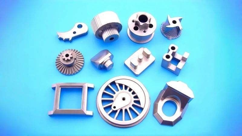
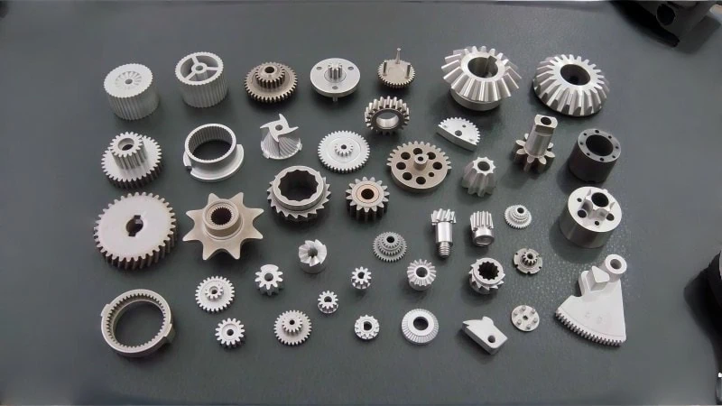
Powder metallurgy is frequently used to manufacture complex geometries like automotive gears, sprockets, and oil pump rotors. These parts often require facing or turning operations across teeth or splines.
This creates a severe interrupted cut. Every time the tool passes a gap between gear teeth, it exits the cut and then re-enters the metal with a heavy impact.
- Ceramic Tools: While ceramics are hard and handle heat well, they are often too brittle. Like a glass plate, they shatter under the shock of hitting a gear tooth.
- Cermet Tools: These offer a good finish but lack the toughness to survive the high-frequency impact of hardened particles found in PM parts.
PCBN is unique because it combines the hardness of ceramic with the toughness of a metallic binder. High-content PCBN grades, specifically, use a metallic binder (like Cobalt or Aluminum) that acts as a shock absorber for the hard CBN particles.
Industry Example: Consider facing a sintered oil pump gear with a hardness of HRC 55. A ceramic insert might catastrophically fracture after processing just 5 parts due to the shock of the gear teeth. A carbide insert might survive the impact but will lose its size tolerance after 10 parts due to abrasion. A PCBN insert, however, can often process 300 to 500 parts reliably.
Cost efficiency analysis of PCBN versus frequent carbide changes
Many machine shops initially hesitate to use PCBN because the cost per insert is significantly higher than carbide. However, looking at the sticker price is misleading. The true value lies in the Cost Per Part (CPP).
When machining abrasive PM parts, carbide tools wear out incredibly fast. If an operator has to stop the machine every 15 minutes to index (rotate) a carbide insert, the machine is not making money.
PCBN tools typically last 20 to 50 times longer than carbide in hardened PM applications. This extended life translates to massive savings in machine downtime.
Table: Cost Comparison for Machining Hardened PM Gears (Sample Data)
| Cost Factor | Carbide Insert | PCBN Insert |
|---|---|---|
| Insert Cost | $10.00 per corner | $45.00 per corner |
| Tool Life (Parts per corner) | 20 parts | 800 parts |
| Tool Cost Per Part | $0.50 | $0.06 |
| Tool Changes Needed (for 1000 parts) | 50 changes | 1.25 changes |
| Downtime Cost (at $100/hr machine rate) | High (approx. $250) | Low (approx. $6) |
As shown in the table, while the initial tool is more expensive, the PCBN insert reduces the actual tooling cost per part by nearly 90%. More importantly, it frees up hours of machine capacity that were previously wasted on changing worn-out tools. For a deeper understanding of this economic impact, reviewing the Total Cost of Ownership (TCO)4 can provide a clearer picture.

Key Factors in Selecting the Correct PCBN Insert Specification
How do you determine the correct PCBN grade and edge preparation for machining powder metallurgy components?
To successfully machine powder metallurgy (PM) parts, select a PCBN grade with a high CBN content (typically between 75% and 90%) combined with a metallic binder to withstand the abrasive nature of the material. For finish turning, prioritize a fine grain size (1–2 microns) to achieve high surface quality, whereas heavy interrupted cuts require a larger Negative Land (T-land) and honed edge to direct cutting forces into the insert body and prevent chipping.
Choosing the optimal CBN grain size for finish turning
The grain size of the PCBN material dictates the quality of the surface finish and the sharpness of the cutting edge. In the context of powder metallurgy, this choice is critical because PM parts are often near-net shapes. This means the machining process is usually a finishing operation rather than heavy roughing.
Fine-grain PCBN (approximately 1 to 2 microns) is generally the industry standard for finishing PM parts.
- Sharper Edges: Smaller grains allow the insert to be ground to a sharper edge. A sharper edge shears the metal cleanly rather than plowing it. This is vital when cutting porous materials to prevent “smearing” metal over the pores.
- Wear Resistance: Fine grains offer excellent resistance to abrasive wear, which is common when machining PM parts containing hard additives.
In contrast, coarse-grain PCBN (usually 10 microns or larger) is tougher but cannot hold a sharp edge. Using a coarse grain on a precision bearing cap or gear face often results in a rough surface finish that fails quality control.
Think of this like choosing the grit for a grinding wheel. A coarse grit removes material fast but leaves deep scratches. A fine grit removes less material but leaves a polished, smooth surface. Similarly, fine-grain PCBN provides the necessary finish for precision PM components.
Binder selection strategies for heavy versus light interruptions
The binder is the material that “glues” the CBN particles together. While the CBN provides the hardness, the binder determines the toughness. This is the most important factor when dealing with the inherent porosity of PM parts.
For Powder Metallurgy applications, we typically categorize binders into two groups based on the severity of the cut.
1. Metallic Binders (Cobalt or Aluminum-based)
These are the heavy lifters. When machining PM gears with teeth, splines, or holes, the tool experiences severe mechanical shock. Metallic binders act like a shock absorber. They hold the CBN particles firmly, preventing them from shattering under impact.
- Best for: Interrupted cuts, gears, and parts with low density (high porosity).
2. Ceramic Binders (TiC or TiN-based)
These binders are more chemically stable but more brittle. They are excellent for heat resistance but struggle with impact. In PM machining, these are less common unless the part is fully dense and the cut is continuous (no interruptions).
- Best for: Continuous turning of high-density PM parts where crater wear is the main concern.
Table: Binder Recommendation by Operation
| PM Machining Condition | Recommended Binder Type | Reason |
|---|---|---|
| Heavy Interruption (e.g., Gear teeth, splines) | High-Content Metallic | Provides maximum toughness to prevent breakage during impact. |
| Continuous Cut (e.g., Plain ring, shaft) | Low-Content Ceramic or Mixed | Offers higher chemical stability to resist heat and crater wear. |
| General Purpose | Medium-High Metallic | Balances wear resistance with enough toughness for minor porosity. |
Determining the correct negative land and honing size to prevent chipping
The geometry of the cutting edge, specifically the edge preparation, is your first line of defense against chipping. A “sharp” edge is actually weak. When a sharp edge hits a hard particle or a pore in the PM part, it tends to chip instantly.
To fix this, manufacturers apply a Negative Land (T-land) and a Hone.
- The T-land (Chamfer): This is a small angled flat ground onto the cutting edge. It changes the direction of the cutting force. Instead of pulling on the edge (tensile stress), the force pushes into the body of the insert (compressive stress). PCBN is incredibly strong under compression.
- The Hone: This is a rounding of the sharp transition points. It removes microscopic defects that could start a crack.
Standard Specifications for PM Parts:
- For Light Cuts: A common specification is a 0.10mm x 20° T-land. This protects the edge without generating too much heat or pressure.
- For Heavy Interruptions: You need a stronger edge, such as 0.20mm x 25° T-land. This is standard for facing gears where the tool hits the teeth repeatedly.
Imagine a milling cutter taking a heavy cut. If the corner of the end mill is perfectly sharp, it snaps. If the corner has a small radius (bull nose), it survives the impact. The T-land on a PCBN insert performs that same protective function for the turning tool.

Practical Machining Parameters for Extended Tool Life
What are the optimal cutting speed, feed rate, and coolant strategies for machining hardened powder metallurgy components with PCBN inserts?
For hardened powder metallurgy applications (typically 45–60 HRC), maintain a cutting speed (Vc)5 between 100 and 250 m/min to generate beneficial softening heat without accelerating abrasive wear. Keep feed rates (f) relatively low, generally between 0.05 and 0.15 mm/rev, to prevent surface pitting known as “pore breakout.” Furthermore, dry machining is predominantly recommended to avoid thermal shock, which can cause micro-cracking in the PCBN insert structure.
Recommended cutting speeds for hardened sintered alloys
Finding the right cutting speed for PCBN is a balancing act. Unlike carbide, which fails if it gets too hot, PCBN actually needs heat to work effectively. The friction heat softens the workpiece material directly in front of the cutting edge. This process is called “plasticization.”
If you run the machine too slowly (e.g., below 80 m/min), the metal stays hard and brittle. This causes the PCBN edge to chip because it is essentially hammering against cold, hard steel particles.
However, Powder Metallurgy adds a twist: abrasion. Because PM parts contain hard oxides and carbides, running too fast turns the part into a grinding wheel. High speeds increase the rubbing action against these abrasive particles, which wears down the tool flank rapidly.
Therefore, the “sweet spot” for PM parts is generally lower than what you would use for solid hardened steel.
Table: Suggested Cutting Speeds for PM Parts
| Workpiece Hardness | Cutting Speed (Vc) | Operational Goal |
|---|---|---|
| HRC 45–50 | 180 – 250 m/min | Higher speed allowed; focuses on productivity. |
| HRC 50–55 | 150 – 200 m/min | Balanced speed to manage heat and abrasion. |
| HRC 55–60+ | 100 – 160 m/min | Conservative speed to prevent thermal damage to the binder. |
Note: These speed ranges are general baselines. Since specific alloy blends and machine rigidity vary, always consult your insert supplier’s data sheet for the exact parameters regarding your specific grade.
Think of this like optimizing a grinding process. If the wheel speed is too high, you generate excessive heat and glaze the wheel (abrasive wear). If the speed is too low, the grains tear out instead of cutting (chipping). You need a moderate speed to cut efficiently without destroying the abrasive properties.
Feed rate guidelines to avoid pore breakout and surface defects
The feed rate is the critical factor controlling surface finish, but in PM parts, it controls something even more important: Pore Breakout.
Pore breakout happens when the cutting tool pushes material into a pore rather than shearing it off cleanly. As the tool passes, that pushed material rips away, leaving a large, ugly pit on the surface. This looks like the metal has been “plucked” out.
To prevent this, the feed rate must be kept low enough to ensure the cutting force remains directed sharply into the cut.
- Standard Finishing: A feed rate of 0.05 to 0.10 mm/rev is safest. This ensures the force shears the metal cleanly across the pores.
- Wiper Inserts: If you need faster production, use a “Wiper” geometry insert. This allows you to double the feed rate (e.g., up to 0.20 mm/rev) while still “ironing” the surface smooth, closing up the pores visually.
Industry Experience: In the manufacturing of automotive valve seats (a common PM part), increasing the feed rate beyond 0.15 mm/rev often results in failing the surface roughness (Ra) test immediately. The surface might look okay to the naked eye, but under a microscope, the pores look torn and jagged.
Dry versus wet cutting strategies for maximizing PCBN performance
One of the most common mistakes in machining PM parts is flooding the zone with coolant. Operators often think, “It’s hard turning, so it must be hot, so I need coolant.” This is usually wrong for PCBN.
As discussed, PCBN needs heat to soften the metal. If you spray coolant, you are over-cooling the cut.
More importantly, the porous nature of PM parts creates an interrupted cut. The tool heats up in the metal and cools down in the void.
- Dry Machining (Recommended): The temperature stays relatively stable. The tool wears slowly and predictably.
- Wet Machining (Risky): The coolant hits the hot cutting edge every time it exits a cut or hits a pore. This rapid heating and quenching causes Thermal Shock6. It creates tiny vertical cracks on the insert edge, leading to premature breakage.
When should you use coolant?
You should only use coolant if dimensional stability is an issue—for example, if the workpiece wall is so thin that the heat from machining warps the part size. In this case, do not use a “flood” of coolant. Instead, use high-pressure coolant directed precisely at the chip to break it, or ensure the coolant supply is 100% continuous so the tool never experiences a dry-wet cycle. But for 90% of PM turning jobs, keep it dry.
Troubleshooting Common PCBN Failure Modes in PM Machining
What are the most frequent causes of PCBN insert failure when turning powder metallurgy parts, and how can operators correct them immediately?
The two primary failure modes for PCBN in powder metallurgy applications are crater wear, caused by excessive heat and chemical reactions, and edge chipping, resulting from mechanical shock against material pores. To resolve crater wear, reduce the cutting speed to lower the interface temperature; to stop edge chipping, increase the edge preparation size (hone and negative land) or switch to a tougher PCBN grade with higher metallic binder content.
Identifying and fixing crater wear caused by chemical reaction
Crater wear appears as a hollow depression on the top surface (rake face) of the insert, just behind the cutting edge. While PCBN is extremely hard, it is not immune to heat.
When machining PM parts at very high speeds, the temperature can rise enough to trigger a chemical reaction. Although Boron Nitride itself is inert, the binder material holding the CBN particles together (often Cobalt or Aluminum) can react with the iron in the workpiece.
- The Cause: High cutting speeds generate excessive heat. This heat softens the binder, allowing the abrasive chips flowing over the insert to erode the top surface.
- The Risk: If the crater grows too large, it weakens the cutting edge structure. Eventually, the edge will collapse under the cutting pressure, leading to catastrophic breakage.
How to Fix Crater Wear:
- Reduce Cutting Speed (Vc): This is the most effective fix. Dropping the speed by 10% to 20% significantly lowers the chemical reactivity.
- Check the Feed Rate: If the feed is too low, the tool rubs rather than cuts, generating unnecessary heat. Ensure the feed is sufficient to create a proper chip.
- Inspect the Binder: If you are using a grade with a high percentage of metallic binder and still see rapid cratering, you might need a grade with a more heat-resistant ceramic binder, provided the interruption is light.
Table: Diagnosing Crater Wear vs. Flank Wear
| Wear Type | Visual Appearance | Primary Cause in PM Parts | Corrective Action |
|---|---|---|---|
| Crater Wear | A “scoop” or divot on the top of the insert. | Chemical reaction due to high heat (Speed is too high). | Decrease cutting speed. |
| Flank Wear | An abrasive flat spot on the side of the insert. | Normal abrasion from hard particles (Speed is too low or normal). | Increase speed slightly or accept as normal wear. |
Note: Determining the exact cause of wear requires a magnifying glass or microscope. Always compare your used insert against a wear chart provided by your supplier.
Solving edge chipping issues in highly porous materials
Edge chipping is the most common and frustrating issue when machining powder metallurgy parts. It looks like small notches or jagged breaks along the cutting edge, rather than smooth wear.
This is a mechanical failure, not a thermal one. As discussed earlier, the pores in PM parts act like micro-interruptions. If the cutting edge is too sharp or too brittle, the constant “hammering” force of entering and exiting these pores will fracture the CBN crystals.
Technical Analogy: Think of this like using a milling cutter. If you run a delicate finishing end mill into a rough weld seam, the corners will snap. You need a tool with a stronger, reinforced corner geometry to survive the impact. The same applies here.
Steps to Resolve Edge Chipping:
- Increase the Negative Land (T-land): If you are using a standard 0.10mm T-land and seeing chipping, switch to a 0.20mm width. This forces the cutting load into the solid body of the insert rather than the weak edge.
- Increase Honing Size: A larger hone (radius on the edge) removes microscopic sharp points that are prone to fracture.
- Switch to a Tougher Grade: If geometry changes do not work, the PCBN material itself may be too brittle. Move to a grade with a higher CBN content (e.g., shifting from 75% to 90% CBN). High-CBN grades have more metallic binder, making them tougher against impact.
- Check Center Height: Ensure the tool is not set above the center line. Being above center increases pressure on the flank and can cause immediate chipping on PM parts.
Industry Tip: If the chipping happens immediately upon entering the cut, it is likely a rigidity or setup issue. If the chipping happens after a few minutes of cutting, it is likely due to the edge wear weakening the tool, suggesting you need a more wear-resistant grade.
Conclusion
Machining powder metallurgy parts requires a specialized approach that balances heat generation with impact toughness. By understanding the unique interactions between PCBN inserts and porous sintered alloys, manufacturers can drastically reduce tool wear and cycle times.
Are you experiencing inconsistent tool life or poor surface finishes on your PM components?
Contact us today to discuss your specific application. Our engineering team can help you select the precise PCBN grade and edge preparation to optimize your production.
References
- Polycrystalline Cubic Boron Nitride (PCBN) inserts1 – ZYDiamondTools product page offering PCBN inserts optimized for processing hardened powder metallurgy and steel parts.
- Struggling with Interrupted Cuts?2 – ZYDiamondTools guide on how PCBN tools solve issues with interrupted cutting conditions.
- Your Complete Guide to CBN Cutting Tools3 – ZYDiamondTools comprehensive guide on PCBN material properties and applications.
- Total Cost of Ownership (TCO) Explained4 – ZYDiamondTools article explaining how to calculate the true cost of tooling beyond the initial price.
- Speeds & Feeds Calculator5 – ZYDiamondTools utility page for calculating optimal machining parameters.
- Thermal Shock6 – Wikipedia article explaining the physics of thermal shock and its effect on materials.


