-
Whatsapp: +86 13526572721
-
Email: info@zydiamondtools.com
-
Address: AUX Industrial Park, Zhengzhou City, Henan Province, China
-
Whatsapp: +86 13526572721
-
Email: info@zydiamondtools.com
-
Address: AUX Industrial Park, Zhengzhou City, Henan Province, China

PCD Tools for Aluminum: A Complete Guide to Higher Performance

For manufacturers working with aluminum, what is the most effective strategy to significantly boost performance, extend tool life, and lower overall production costs?
The most effective strategy is the adoption of Polycrystalline Diamond (PCD) tooling. This approach solves common machining problems like poor surface finish and rapid tool wear, enables ultra-high cutting speeds, and drastically reduces cost-per-part. Success requires selecting the correct tool type for the operation, matching the PCD grade to the aluminum’s silicon content, and optimizing the setup with rigid holders and high-pressure coolant.
What Common Problems Does PCD Solve in Aluminum Machining?
When working with aluminum, a common and often frustrating issue for manufacturers is dealing with challenges like poor surface quality, tools wearing out too fast, and production being too slow. So, what is the single most effective solution to these persistent problems that can sabotage your aluminum machining process?
Polycrystalline Diamond (PCD) is the superior tooling solution for aluminum. Its unique properties—extreme hardness, low friction, and high thermal conductivity—directly solve the core challenges by eliminating poor finishes, drastically extending tool life, and enabling the high-speed machining required for maximum productivity and a lower cost-per-part.
Eliminating Poor Surface Finish and Built-Up Edge (BUE)
One of the biggest headaches when machining soft, sticky metals like aluminum is getting a poor surface finish. This often happens because of a phenomenon called Built-Up Edge (BUE)1.
What is Built-Up Edge (BUE)?
BUE occurs when chips of aluminum weld themselves to the cutting edge of the tool.
- This makes the tool’s geometry incorrect.
- The actual cutting edge becomes uneven and rough.
- This rough edge then tears at the aluminum workpiece instead of cleanly shearing it.
- The result is a poor, often unacceptable, surface finish that requires extra steps like polishing, which wastes time and money.
How PCD Stops BUE
PCD is an excellent solution because of two key properties:
- Extreme Hardness and Sharpness: PCD’s uniform microstructure allows it to be ground to an incredibly sharp edge. This razor-sharp edge creates a clean shear action, minimizing the friction and pressure that cause aluminum to stick.
- Low Friction and Non-Stick Surface: Diamond has a very low coefficient of friction. This means the aluminum chip slides easily over the PCD tool face. The reduced friction also lowers the heat at the cutting zone, which further prevents the aluminum from softening and welding itself to the tool.
In real-world applications, switching to PCD for fine finishing passes on high-precision aluminum components can routinely achieve surface roughness values (Ra)2 far superior to those possible with carbide, often allowing manufacturers to meet strict aerospace or automotive standards without secondary finishing operations.
Solving Rapid Tool Wear and Frequent Tool Changes
Aluminum, especially high-silicon aluminum alloys (those with a silicon content above 8%), is surprisingly abrasive. Silicon particles are extremely hard, essentially acting like sandpaper against traditional carbide tools.
The Problem of Abrasion and Flank Wear
Traditional carbide tools, while hard, quickly suffer from abrasion and flank wear when cutting these silicon-rich alloys.
- As the tool wears down, the cutting forces increase.
- This generates more heat.
- The quality of the part begins to degrade rapidly.
The need to frequently stop the machine to change or index the worn tool leads to costly downtime and inconsistent part quality.
PCD’s Durability Advantage
PCD’s exceptional hardness and wear resistance solve this problem head-on:
- Diamond is the Hardest Known Material: It can withstand the abrasive attack of hard silicon particles without showing significant wear.
- Massive Increase in Tool Life: It is common for a PCD tool to last 50 to 100 times longer than a standard uncoated carbide tool when machining high-silicon aluminum. A deeper dive into the difference between PCD and carbide tools3 reveals why this performance gap is so significant. For instance, a manufacturer might achieve 500 parts with a carbide tool, but over 30,000 parts with the same PCD tool geometry.
This dramatic increase in tool life is the single greatest factor in reducing machine downtime and improving overall manufacturing efficiency.
Overcoming Low Productivity and Long Cycle Times
Machining aluminum should be fast—it is a soft metal. However, traditional tooling materials limit how fast you can run your machine.
The Limitations of Carbide
Carbide and High-Speed Steel (HSS) tools have a limit to the cutting speed they can handle. If you try to increase the Surface Feet per Minute (SFM) too much:
- Heat builds up rapidly, leading to thermal degradation of the tool.
- Tool wear accelerates exponentially.
- The risk of BUE and poor finish becomes unmanageable.
These limitations force manufacturers to use lower feed rates and slower cutting speeds, resulting in longer cycle times for every part.
Unlocking High-Speed Machining with PCD
PCD tooling removes these speed limits:
- Superior Thermal Conductivity: Diamond is an outstanding heat conductor. It pulls heat away from the cutting edge and dissipates it into the chip and the tool body very quickly. This keeps the cutting edge cooler, even at ultra-high speeds.
- Enabling Ultra-High RPMs: With PCD, cutting speeds can often be pushed into the 1,500 to 5,000 SFM range, sometimes even higher. This allows machines to run at their maximum spindle RPM.
By running the machine faster, the time it takes to make one part (cycle time) is drastically reduced, leading to a major boost in productivity and the ability to produce more parts per shift.
Reducing High Overall Cost-Per-Part
The total cost-per-part in manufacturing is not just the price of the tool; it includes all related expenses. When using traditional tools, these costs can stack up quickly.
Hidden Costs of Traditional Tooling
The issues addressed above—rapid wear, frequent changes, and slow speeds—are major drivers of high costs:
| Cost Factor | Cause with Traditional Tooling | Impact on Cost-Per-Part |
|---|---|---|
| Downtime | Frequent tool changes and indexing | Wasted machine time; machine is not making money |
| Tool Inventory | High consumption rate of tools | Need to buy, store, and manage more tools |
| Labor | Time spent by operators changing tools | Increased hourly labor cost per part |
| Rework/Scrap | Poor surface finish or dimensional inconsistency | Cost of wasted material and time on non-conforming parts |
PCD’s Contribution to Lower Manufacturing Costs
PCD’s initial purchase price is higher than carbide, but its performance leads to a far lower total cost of ownership4.
Total Cost-Per-Part = (Tool Cost + Downtime Cost + Labor Cost + Rework Cost) / Number of Parts Produced
Because PCD produces vastly more parts between changes, eliminates or reduces costly secondary finishing, and allows for faster cycle times, the true overall cost-per-part plummets.
In a full production scenario, even a tool that is ten times more expensive to buy can easily pay for itself by lasting 50 times longer and cutting three times faster, ultimately making the final product cheaper to manufacture.
Which PCD Tool Is Right for Your Aluminum Application?
With so many PCD tooling options available—including inserts, end mills, and drills—how can manufacturers accurately determine which specific PCD tool geometry and grade will deliver optimal performance and cost efficiency for their unique aluminum machining task?
The correct PCD tool is selected by matching the required machining operation (e.g., turning, milling, drilling) to the corresponding tool type (Insert, End Mill, or Drill/Reamer) and then choosing a PCD grade based primarily on the silicon content of the aluminum alloy, ensuring that the tool’s geometry, like rake angle and edge preparation, aligns with the precision and finish requirements of the part.
PCD Inserts for Turning and Milling Operations
PCD inserts are the most common type of PCD tool used in manufacturing. These are small, replaceable cutting tips brazed with a PCD segment onto a carbide body.
When to Choose Inserts
Inserts are primarily used for turning (lathes) and general milling (indexable face mills or shoulder mills).
- Turning: If you are machining round aluminum parts, such as automotive pistons or large hydraulic components, a PCD turning insert5 is the ideal choice for achieving a mirror-like finish and high material removal rates.
- Milling: For roughing and semi-finishing large flat surfaces or pockets, indexable milling cutters that hold PCD inserts offer maximum stability and cost-effectiveness. When one edge wears, you simply rotate (index) the insert to a fresh, sharp edge.
Key Insert Features
The design of the PCD insert is critical for chip control and tool life:
| Feature | Primary Function in Aluminum Machining |
|---|---|
| PCD Tip Shape | Dictates the length of cut and heat distribution. Larger tips offer better thermal stability. |
| Rake Angle | A positive rake angle is essential for aluminum to promote clean shearing action and reduce BUE. |
| Chip Breaker | Grooves or features molded into the insert face to curl and break long, stringy aluminum chips into manageable pieces. |
| Nose Radius | A larger nose radius provides better surface finish and increased edge strength but can increase vibration risk. |
For example, when turning a large aluminum gearbox housing, using an insert with a high positive rake and a polished edge finish ensures that the material is cut cleanly, preventing the soft aluminum from sticking.
PCD End Mills for High-Speed Finishing
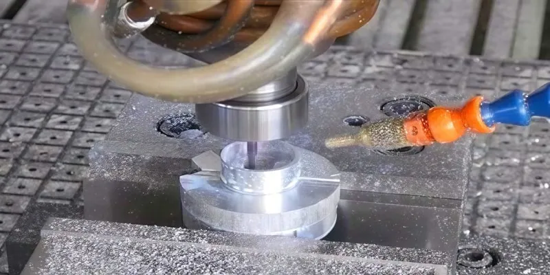
Unlike indexable tools, PCD end mills are solid, single-piece cutting tools primarily used in high-speed applications on machining centers.
Focus on Precision and Speed
PCD end mills are generally chosen for applications that demand:
- Ultra-High Speed: They are balanced and designed for extremely high rotational speeds (up to 30,000 RPM or more) necessary to achieve maximum cutting speeds in aluminum.
- Superior Surface Finish: They are the go-to tool for finishing passes on critical components like molds, aerospace structural parts, or automotive cylinder heads, where the final surface quality must be perfect.
- Complex Geometry: They can machine deep pockets, intricate contours, and small features that indexable tools cannot reach.
Solid PCD vs. Veined PCD
You will encounter two main constructions for PCD end mills:
- Solid PCD: The entire cutting tip is solid PCD. These are expensive but offer the longest tool life and best heat dissipation.
- Veined PCD: A small, precision-ground vein or strip of PCD is brazed into the flutes of a carbide end mill. This is a common, cost-effective method for balancing performance and price.
For achieving mirror-like surface finishes (Ra less than 0.4 μm) on complex aluminum components, a 2-flute PCD end mill6 with a helix angle often optimized for aluminum (e.g., 30° to 45°) is typically employed. As optimal helix angle and number of flutes can vary based on machine rigidity and cooling, it is prudent to confirm the specific parameters with your tool supplier.
PCD Drills and Reamers for Precision Holes
Producing accurate and high-quality holes in aluminum is challenging due to the material’s tendency to create BUE and long chips. PCD solves both issues.
PCD Drills
PCD-tipped drills7 are specifically designed for drilling large volumes of holes or achieving high-precision bore tolerances.
- Core Benefit: Their highly wear-resistant edges maintain hole diameter and straightness over thousands of cycles, which is critical in production environments.
- Design: PCD is typically brazed onto the outer corners of a carbide drill body. This ensures that the most heavily loaded parts of the cutting edge (the corners) benefit from the diamond’s durability.
PCD Reamers
When a hole needs an extremely tight tolerance (e.g., an H7 fit) and a superior surface finish, a PCD reamer8 is essential.
- The Ultimate Finish: Reamers remove a minimal amount of material but ensure the final hole is perfectly round and smooth. PCD reamers maintain their size for much longer than carbide, which is vital for maintaining consistent hole geometry across a large batch of parts.
- Industry Example: In the manufacturing of critical valve bodies, a PCD reamer is often used to size the final bore, ensuring the hydraulic spool operates smoothly and reliably without leakage.
Selecting the Right Grade for High-Silicon vs. Low-Silicon Alloys
Aluminum alloys are defined by their composition, particularly the percentage of silicon (Si), which is the key factor in determining the correct PCD grade. This is where PCD expertise is crucial.
Understanding the Alloy’s Silicon Content
The aluminum-silicon content dictates how abrasive the material is:
- Low-Silicon Alloys (Si < 8%): These alloys, like 6061 or 7075, are softer and less abrasive. The primary risk is BUE and sticking.
- High-Silicon Alloys (Si ≥ 8%): These, such as A390 (up to 18% Si), are highly abrasive because the hard silicon particles act like tiny ceramic bits. The primary risk is rapid tool wear.
Matching the PCD Grade
PCD material itself comes in different grain sizes, which are designated as grades. The grain size directly affects the tool’s hardness and toughness.
| Aluminum Alloy Type | Recommended PCD Grain Size | Key Performance Benefit |
|---|---|---|
| High-Silicon (Si ≥ 12%) | Coarse Grain (e.g., 25 μm to 50 μm) | Highest abrasion resistance and toughness against hard silicon particles. |
| Medium-Silicon (Si < 12%) | Medium Grain (e.g., 10 μm to 25 μm) | Good balance of wear resistance and edge quality for general use. |
| Low-Silicon (Si < 8%) | Fine Grain (e.g., 2 μm to 10 μm) | Can be honed to a razor-sharp edge, minimizing BUE and achieving the best surface finish. |
Selecting a coarse-grain PCD for high-silicon A390 aluminum is necessary because its tougher structure holds up better against extreme abrasion. Conversely, using a fine-grain PCD on softer 6061 aluminum provides the sharpest edge needed to prevent BUE and produce a mirror-like finish. Always verify the exact grain size range and application guidelines with your tool manufacturer, as grade classifications can vary.
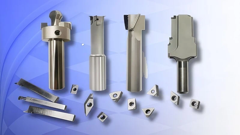
Maximizing Results with PCD Tooling
Now that you’ve selected the right PCD tool, how do you unlock its full potential to achieve the highest performance, longest life, and best return on your investment in every single aluminum part you machine?
To maximize results with PCD, you must focus on three critical areas: first, select tools with superior technical specifications like high-quality brazing and precise balance; second, implement best practices for setup and operation, including ensuring machine rigidity and using high-pressure coolant; and third, effectively troubleshoot common issues like poor finish or premature chipping by understanding their root causes.
Key Technical Specifications to Look For
Not all PCD tools are created equal. When purchasing PCD tooling, paying close attention to the technical specifications on the manufacturer’s data sheet is the first step toward achieving superior performance.
Edge Preparation and Finish
The condition of the cutting edge is paramount, especially for aluminum.
- Sharp, Polished Edge: For most aluminum applications, you want a razor-sharp edge with a highly polished (low friction) surface. This is the best defense against Built-Up Edge (BUE), as it promotes clean shearing and allows chips to slide off easily.
- Honed Edge: A honed edge has a very small, deliberate radius applied. While less common for aluminum, a light hone can add strength to the cutting edge for heavy roughing or interrupted cuts.
Brazing Quality
The PCD segment is attached to the carbide tool body through a process called brazing. The quality of this braze joint is a direct indicator of the tool’s durability. A poor braze joint with voids or gaps can act as a stress point, leading to catastrophic failure of the PCD tip under high cutting forces. Always source tools from reputable manufacturers known for their consistent, high-quality brazing processes.
Tool Balancing and Runout
For tools that spin at high RPMs, like end mills and drills, balance and runout are non-negotiable specifications.
- Balancing: An unbalanced tool spinning at 20,000 RPM creates immense centrifugal force, leading to vibration, poor surface finish, and premature spindle wear. It’s like driving a car with unbalanced tires. Look for tools that are balanced to a specific grade, such as G2.5, for high-speed applications.
- Runout: This refers to how much the tool “wobbles” off-center as it rotates. High runout concentrates cutting forces on one part of the edge, causing rapid wear and chipping. For precision finishing, total tool runout should be extremely low, ideally less than 5 microns (0.0002”).
Best Practices for Setup and Operation
Even the best PCD tool will underperform if the machine environment and operating parameters are not optimized.
Machine and Tool Holder Rigidity
PCD tools achieve their best results at high speeds, but high speed can amplify any instability in the setup.
- Stable Machine: The CNC machine itself must be rigid and well-maintained. Any play in the spindle bearings or machine ways will translate into vibration (chatter9) at the cutting edge, which can easily chip the brittle PCD tip.
- High-Quality Tool Holders: The connection between the machine spindle and the tool is critical. Standard collet chucks may not provide sufficient grip or concentricity. For high-speed PCD machining, using high-performance holders like shrink-fit, hydraulic, or high-precision milling chucks is essential to minimize runout and maximize stability.
High-Pressure, High-Volume Coolant
Coolant is not just for cooling; its most important job in high-speed aluminum machining is chip evacuation.
Think of the coolant stream as a fire hose. Its job is to blast chips out of the cutting zone and away from the workpiece. If chips are allowed to accumulate, the tool will re-cut them, leading to a damaged edge and a scrapped part.
For operations like deep pocketing or drilling, using through-spindle coolant is the most effective method for flushing chips out of the hole and preventing them from packing.
Optimized Toolpaths and Programming
How you program the tool’s path has a direct impact on its life.
- Avoid Sudden Impacts: PCD is very hard, but also brittle. Programming the tool to slam into a sharp corner or take a heavy, abrupt cut can cause it to chip.
- Use Smooth Toolpaths: Employ modern programming strategies like High-Speed Machining (HSM). These toolpaths use smooth, arcing motions, maintain a consistent tool engagement, and avoid sharp directional changes, which is ideal for preserving the delicate PCD cutting edge while maximizing metal removal rates.
Troubleshooting Common Machining Issues
When problems arise, a systematic approach can help you identify and solve them quickly. The table below outlines common issues and their likely causes and solutions when machining aluminum with PCD.
| Problem | Possible Causes | Potential Solutions |
|---|---|---|
| Poor Surface Finish | – Built-Up Edge (BUE) on the tool – Excessive tool runout or vibration – Wrong PCD grade (too coarse) – Coolant not reaching the cutting edge | – Inspect and clean the tool edge – Check runout; use a more rigid tool holder – Switch to a finer grain PCD for better sharpness – Reposition or increase coolant pressure/volume |
| Premature Chipping or Tool Failure | – Vibration or chatter in the setup – Interrupted cuts or harsh tool entry – Chips are being re-cut – Feed rate is too high | – Stiffen workholding; reduce tool stick-out – Program smooth entry/exit paths (arc in/out) – Improve chip evacuation with better coolant flow – Reduce feed per tooth; consult supplier data |
| Loud or High-Pitched Squealing | – Chatter/vibration – Tool is rubbing, not cutting – Incorrect speeds and feeds | – Adjust RPM to a more stable range – Increase feed rate to ensure proper chip load – Verify cutting parameters with tool manufacturer |
| Inconsistent Hole Size (Drilling/Reaming) | – Tool is worn – Chips are packing in the flutes – High tool runout | – Inspect the PCD edges for wear – Use through-spindle coolant or peck drilling cycle – Re-indicate the tool to minimize runout |
Remember, these are general guidelines. The best source of specific troubleshooting advice for your application will always be your tooling supplier, as they can provide recommendations tailored to their specific tool geometries and PCD grades.
Conclusion
Transitioning to Polycrystalline Diamond tooling is more than just a material upgrade; it is a strategic shift towards a more efficient, productive, and cost-effective manufacturing process for aluminum components. By understanding the fundamental problems that PCD solves, carefully selecting the right tool and grade for each specific application, and committing to best practices in setup and operation, manufacturers can unlock unprecedented levels of performance. This comprehensive approach ensures that the initial investment in PCD pays significant dividends through superior part quality, massively extended tool life, and a dramatic reduction in the all-important cost-per-part.
For any challenges in your aluminum machining applications, contact our experts to explore our full range of PCD tooling solutions.
References
- Built-Up Edge (BUE)1 – A Wikipedia article explaining the phenomenon of built-up edge in metal cutting.
- Surface roughness values (Ra)2 – A Wikipedia article detailing the concept of surface roughness and its measurement parameters, including Ra.
- Difference between PCD and carbide tools3 – An in-depth comparison from ZYDiamondTools detailing the performance differences between these two materials.
- Total cost of ownership4 – A ZYDiamondTools guide explaining the TCO concept specifically for superhard tooling.
- PCD turning insert5 – Product page for standard and custom PCD inserts for various machining operations.
- 2-flute PCD end mill6 – Product page for a 2-flute PCD end mill, ideal for high-speed finishing of aluminum.
- PCD-tipped drills7 – Product page for PCD drilling tools designed for aluminum and other non-ferrous materials.
- PCD reamer8 – Product page for high-precision PCD reamers used for achieving tight hole tolerances.
- Chatter9 – A Wikipedia article explaining the science behind machining vibrations, commonly known as chatter.
