-
Whatsapp: +86 13526572721
-
Email: info@zydiamondtools.com
-
Address: AUX Industrial Park, Zhengzhou City, Henan Province, China
-
Whatsapp: +86 13526572721
-
Email: info@zydiamondtools.com
-
Address: AUX Industrial Park, Zhengzhou City, Henan Province, China

Why Choose PCD Tools for Graphite Machining and How to Select the Right One?

So, what is the complete picture for successfully using PCD tools to machine graphite?
Choosing and using the right PCD tool for graphite involves a systematic approach. First, you must understand that graphite is highly abrasive and brittle. Second, select the correct type of PCD tool—such as mills or drills—for the specific operation. Third, specify the tool correctly by choosing the right PCD grade and geometry. Finally, maximize the tool’s performance and lifespan by using optimal cutting parameters and best practices for handling and maintenance.
What Makes Graphite Challenging to Machine?
So, what is it about a material that feels as soft as pencil lead that makes it so tough to machine properly?
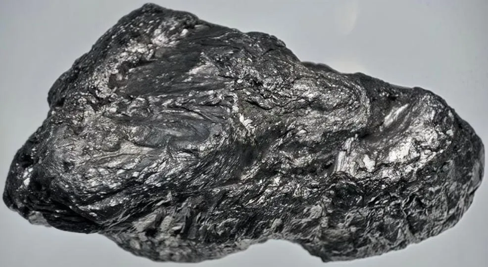
Graphite presents a unique machining paradox: it is soft yet highly abrasive, brittle, and generates fine, conductive dust. This combination leads to extremely rapid tool wear, risks of workpiece chipping, and potential damage to machine electronics, making it a surprisingly difficult material to process effectively.
Understanding Graphite Unique Properties (High Abrasiveness Despite Softness)
At first touch, graphite feels soft and almost greasy. This softness is misleading. While the bulk material is not hard, its microscopic structure is filled with small, extremely hard carbon crystals.
Think of it like this: a piece of sandpaper feels flexible and soft in your hand, but its surface is covered in hard, sharp mineral grains that can wear down solid steel. Graphite acts in a very similar way. As a cutting tool moves through the material, these tiny, abrasive crystals act like microscopic sandpaper, grinding away at the tool’s cutting edge. This phenomenon is called abrasive wear1, and it’s the primary reason conventional tools fail so quickly when machining graphite.
Furthermore, the properties of graphite can vary significantly between grades, such as isostatic or extruded graphite, which affects its density and grain size. A finer grain size often results in a more abrasive material.
Common Machining Issues
The unique properties of graphite lead directly to a set of common, costly problems on the shop floor. Effectively managing these issues is key to profitable graphite machining.
Rapid Tool Wear
This is the most significant challenge. The abrasive nature of graphite can destroy a standard uncoated carbide tool in a matter of minutes. The cutting edge, which needs to be razor-sharp to slice cleanly, quickly becomes rounded and dull. A dull tool can’t cut efficiently; instead, it starts to rub and push against the material, which leads to other problems like poor surface finish and chipping. For instance, in the production of graphite electrodes for EDM (Electrical Discharge Machining), a worn tool can lead to inaccurate electrode geometry, which would make the final mold cavity incorrect.
Brittleness and Chipping
Unlike metals, which bend or deform before they cut, graphite is brittle. It doesn’t create long, flowing chips. Instead, it fractures and breaks away as fine dust or small fragments. This brittleness poses a major risk to the workpiece itself. If the cutting pressure is too high—often a result of a dulling tool—it can easily cause the edges of the workpiece to chip or break out. This is especially problematic when machining thin walls, sharp corners, or intricate details, which are common features in glass molding or casting die applications. A single chip in the wrong place can force you to scrap the entire part.
Dust Control
Machining graphite doesn’t produce chips; it produces a cloud of fine, black dust. This dust is more than just a mess; it’s a triple threat:
- Health Hazard: Inhaling fine graphite particles is a serious respiratory risk for machine operators, requiring shops to implement strict health and safety protocols, including proper ventilation and personal protective equipment (PPE).
- Equipment Risk: Graphite dust is electrically conductive. If it gets into the electronic components of a CNC machine, like the control panel, drives, or motors, it can cause short circuits and lead to catastrophic equipment failure and expensive downtime.
- Machining Interference: The abrasive dust can get trapped between the cutting tool and the workpiece, scratching the surface and ruining the finish.
Because of these risks, dedicated graphite machining centers are often equipped with powerful, specialized vacuum and dust evacuation systems to capture the dust at its source.
Impact on Production Costs and Surface Finish Quality
Ultimately, these machining challenges have a direct and significant impact on your bottom line and the quality of your finished product. When you use the wrong tools for graphite, the costs add up quickly.
| Cost Factor | Impact of Using Inadequate Tools (e.g., Uncoated Carbide) |
|---|---|
| Tooling Costs | Extremely high due to constant tool replacement, often multiple times per shift. |
| Machine Downtime | Significant time lost changing and resetting worn or broken tools, lowering overall productivity. |
| Labor Costs | Increased operator time spent on tool changes and monitoring for wear. |
| Scrap Rate | Higher number of rejected parts due to chipping, fractures, or poor dimensional accuracy. |
| Maintenance Costs | Increased spending on machine cleaning and repairs caused by conductive dust contamination. |
Beyond the direct costs, the quality of the surface finish is critical. As a tool wears, its ability to produce a clean, smooth surface diminishes rapidly. It begins to “plow” through the material rather than shearing it, resulting in a dull, rough, and pitted surface. For applications like molds for consumer electronics or aerospace components, the surface finish of the graphite electrode is paramount, as any imperfection will be directly transferred to the final product. A poor finish on the electrode often requires hours of expensive and labor-intensive manual polishing on the final steel mold to correct the flaws.
Which Types of PCD Tools Are Best Suited for Graphite Processing?
Given the significant challenges of machining graphite—from its extreme abrasiveness to its inherent brittleness—Polycrystalline Diamond (PCD) tools have become the industry-standard solution. Their unparalleled hardness and wear resistance directly counter the issues that cause conventional tools to fail.
With so many options available, which specific PCD tools should you use for different graphite machining tasks?
The best PCD tool for graphite processing depends on the specific operation. For shaping and contouring, PCD milling cutters like end mills and ball nose mills are ideal. For creating holes, PCD drills and reamers are used. For cylindrical parts, PCD turning inserts are the standard choice, while specialized PCD tools handle unique tasks like engraving or grooving.
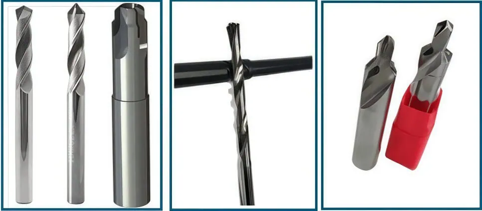
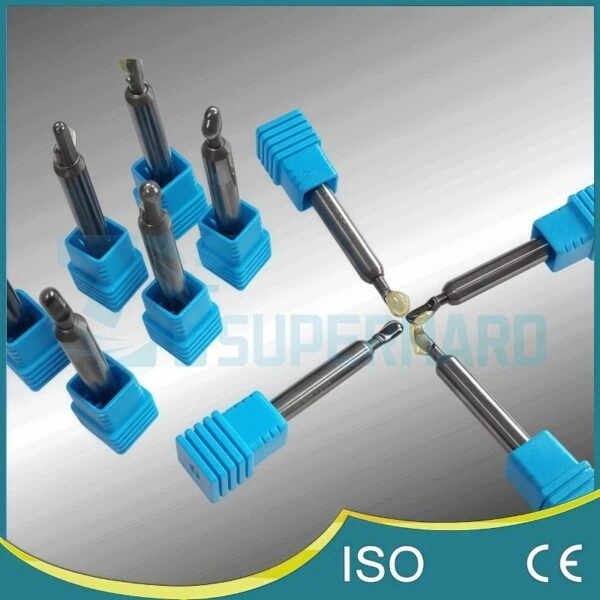
PCD Milling Cutters (End Mills, Face Mills, Ball Nose)
Milling is the most common process for shaping graphite, especially for creating the complex 3D electrodes used in EDM. Because graphite machining is essentially a high-wear grinding process, using the correct PCD milling cutter2 is essential for achieving accuracy and efficiency.
- PCD End Mills: These are the versatile workhorses for graphite machining. They are used for general-purpose tasks like creating pockets, profiling edges, and cutting slots. A high-quality PCD end mill will have diamond segments brazed onto the tips of its carbide flutes. For example, when manufacturing a graphite mold for a car dashboard, PCD end mills are used to rough out the main shape and machine the deep pockets for components like air vents and instrument panels.
- PCD Face Mills: When you need to machine a large, flat surface on a graphite block for an aerospace mold, a PCD face mill is the right tool. These cutters are larger in diameter and use multiple replaceable PCD inserts. Their primary job is to flatten raw graphite blocks or prepare a large, smooth reference surface, ensuring the workpiece is perfectly flat before any detailed finishing work begins.
- PCD Ball Nose Mills: To create smooth, flowing 3D surfaces on graphite electrodes, you need a PCD ball nose mill. The tool’s rounded tip allows it to perform intricate surfacing operations. They are critical for applications like creating the graphite molds used to manufacture consumer electronics, where smooth, curved surfaces are essential for the final product’s look and feel.

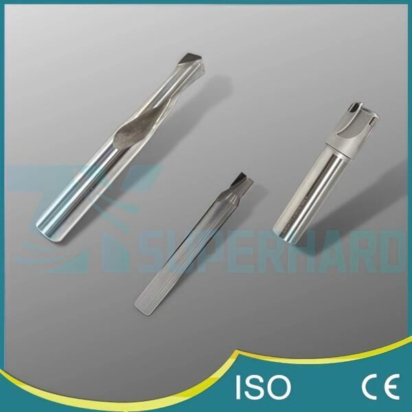
PCD Drilling and Holemaking Tools (Drills, Reamers, Boring Tools)
Creating clean, accurate holes in graphite is impossible without the right tools. The brittleness of the material means that standard drills will cause chipping at the entry and exit points, while the abrasiveness will wear them out almost instantly.
- PCD Drills: For creating holes from scratch in graphite, PCD-tipped drills are the standard. The PCD tip provides the durability needed to drill thousands of holes without significant wear, ensuring consistent hole quality. A common application is drilling arrays of small holes in graphite plates used as fixtures in the solar panel manufacturing industry.
- PCD Reamers: A reamer is not used to create a hole, but to finish it. After a hole is drilled in a graphite component, a PCD reamer3 is used to enlarge it by a very small amount to achieve a highly precise diameter and a very smooth internal surface finish. This is crucial for components like graphite bearings or bushings where tight tolerances are non-negotiable.
- PCD Boring Tools: When a large or custom-sized hole is needed, a PCD boring tool is used. This tool typically has a single adjustable PCD cutting point. It can be set to enlarge an existing hole to any precise diameter required. For example, boring tools are used to machine the large internal cavity of a graphite crucible, a container used for melting metals or growing crystals in the semiconductor industry.
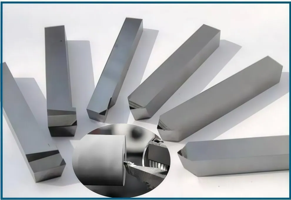
PCD Turning Tools and Inserts
Turning operations involve spinning a cylindrical graphite workpiece while a stationary cutting tool removes material. This is common for making parts like long electrodes for EDM, heating nozzles, or industrial rollers.
Instead of a solid tool, turning operations on graphite almost always use PCD inserts4. These are small, indexable tips made of PCD that are mounted in a steel toolholder. This design is highly economical; when a cutting edge eventually wears down, you don’t replace the entire tool. You simply rotate or replace the small insert itself, which is much cheaper and faster. For long, cylindrical graphite electrodes, using a PCD turning insert ensures that the diameter remains perfectly consistent along the entire length.
Specialized PCD Tools (Engraving, Grooving, Custom Profiles)
Sometimes, standard shapes aren’t enough. For unique and high-volume graphite applications, specialized PCD tools offer incredible efficiency.
- PCD Engraving Tools: These tools have a very fine point and are used for creating small, detailed features like part numbers or logos directly onto a graphite casting mold or electrode.
- PCD Grooving Tools: As the name implies, these tools are designed to plunge into the graphite to cut specific grooves, such as channels for O-rings in sealing components or slots in heating elements.
- PCD Custom Profile Tools: For high-production manufacturing, it’s often possible to design a custom PCD tool that matches the exact final profile of a part. This “form tool” can create a complex shape in a single pass, drastically reducing cycle times. When developing such a tool, it is essential to work closely with your tooling supplier to ensure the geometry, PCD grade, and edge preparation are perfectly optimized for your specific graphite material and application.

What Key Factors Determine the Ideal PCD Tool Specification?
Beyond just picking the right type of tool, how do you choose the specific technical details for the best performance in graphite?
Determining the ideal PCD tool specification involves four key factors: selecting the right PCD grade and grit size for wear resistance versus edge quality; optimizing the tool geometry like rake and clearance angles for efficient cutting; ensuring proper cutting edge preparation for durability; and matching all these factors to the specific grade of graphite and the machining application.
Selecting the Appropriate PCD Grade and Grit Size
Not all PCD is created equal. The term “PCD grade”5 generally refers to the size of the diamond crystals (grit size) used to make the tool’s cutting edge. This is the single most important factor affecting the tool’s performance in graphite.
Choosing the right PCD grade involves balancing wear resistance against edge quality. Coarse grit PCD incorporates larger diamond crystals, providing the highest abrasion resistance and longest life in demanding roughing operations. In contrast, fine grit PCD uses smaller crystals, which allows for a sharper, keener cutting edge, essential for producing the best surface finish in finishing operations.
| PCD Grade Feature | Coarse Grit (e.g., 25-30 µm) | Fine Grit (e.g., 2-5 µm) |
|---|---|---|
| Primary Advantage | Highest wear resistance and toughness. | Best edge quality and sharpness. |
| Best For | Roughing and high-volume material removal where tool life is the top priority. | Finishing passes and machining intricate details where surface quality is critical. |
| Resulting Finish | Good, functional surface finish. | Excellent, near-polished surface finish. |
| Industry Example | Quickly milling away large amounts of material on a big graphite block for a casting mold. | Machining the final, delicate contours of a graphite electrode for a high-gloss smartphone case. |
It’s important to know that grade classifications and names can vary significantly between manufacturers. Therefore, always consult your tooling supplier’s technical data to understand the specific properties and intended applications of their PCD grades.
Optimizing Tool Geometry (Rake, Clearance, and Helix Angles)
The angles ground onto a cutting tool are critical for managing the brittle nature of graphite and ensuring the tool cuts cleanly and efficiently. The right tool geometry reduces cutting pressure and minimizes the risk of chipping.
- Rake Angle: This is the angle of the cutting face. For a brittle material like graphite, a low positive or even neutral rake angle is often preferred. This promotes a stable shearing action that pushes graphite dust away, preventing the tool from digging in too aggressively and causing fractures.
- Clearance Angle: This is the angle behind the cutting edge. A sufficient clearance angle is vital to prevent the body of the tool from rubbing against the newly machined surface, which would increase friction, heat, and cutting pressure.
- Helix Angle (for milling cutters): This is the angle of the spiral flutes. For graphite machining, a lower helix angle (e.g., 10-20 degrees) is often beneficial because it does a better job of pushing the fine graphite dust down and away from the tool, which aids in dust evacuation.
The Role of Cutting Edge Preparation (Passivation)
A freshly sharpened PCD edge, when viewed under a microscope, can be extremely sharp but also microscopically brittle. Cutting edge preparation, also known as passivation or honing, is a process where a microscopic radius is applied to this ultra-sharp edge. This process slightly reduces initial sharpness but vastly increases the edge’s strength and resistance to micro-chipping when engaging with abrasive graphite particles. This strengthening of the cutting edge significantly extends the tool’s reliable life and prevents premature failure, especially in demanding applications.
Matching the Tool to the Specific Graphite Material and Application
Ultimately, there is no single “best” PCD tool specification. The ideal choice is always a combination of the factors above, tailored to the specific job at hand. The goal is to create a complete system where the tool, the material, and the application are all in harmony.
Here’s how you might apply these principles:
- Scenario 1: Heavy roughing of a large, abrasive graphite block.
- Goal: Maximum material removal and longest possible tool life.
- Ideal Tool: A PCD tool with a coarse grit grade for ultimate wear resistance, a robust geometry with a neutral rake angle, and a heavily prepared cutting edge to prevent chipping under high loads.
- Scenario 2: Finish machining a detailed electrode with thin walls and sharp corners.
- Goal: A flawless surface finish, dimensional accuracy, and zero chipping.
- Ideal Tool: A PCD tool with a fine or sub-micron grit grade for the sharpest edge, a geometry with a high clearance angle to minimize cutting pressure, and minimal edge preparation to ensure the cleanest possible shear.
Achieving the perfect match often involves a discussion with your tooling provider. By sharing details about your graphite material, machine capabilities, and quality requirements, you can work with them to select or even custom-design the ideal PCD tool specification for your application.

How Can You Maximize Performance and Lifespan of PCD Tools on Graphite?
Once you’ve invested in the right PCD tools, what’s the best way to use them to get the most value and longest life?
To maximize PCD tool performance, you must establish optimal cutting parameters like speed and feed, implement a high-efficiency dust evacuation system, follow best practices for tool handling and setup to prevent premature damage, and learn to recognize common wear patterns to know precisely when a tool needs replacement.
Establishing Optimal Cutting Parameters (Speed, Feed, Depth of Cut)
Using a high-performance PCD tool with the wrong machine settings prevents you from realizing the performance you paid for. Cutting parameters are the settings you program into your CNC machine to control how the tool moves through the material. For PCD tools in graphite, high cutting speeds are recommended as they allow the hard PCD edge to cleanly shear the brittle material rather than pushing it. The feed rate must be carefully optimized to ensure a consistent chip load that avoids both rubbing (if too slow) and chipping the workpiece (if too fast). The depth of cut will depend on whether you are roughing (removing large amounts of graphite) or finishing (taking a very light pass for surface quality).
Crucial Note: Optimal cutting parameters are not universal. They change based on the specific PCD grade, tool diameter, machine rigidity, and the type of graphite you are machining. Always use the starting parameters recommended by your tooling supplier as your baseline. From there, you can make small adjustments to optimize the process for your specific setup.
Implementing Effective Chip and Dust Evacuation
Graphite dust is the enemy of both your machine and your PCD tools. If this abrasive dust isn’t removed immediately, the tool will end up re-cutting it, which dramatically accelerates wear. The industry standard for managing this is a high-volume vacuum system. A dust shroud is positioned around the cutting tool, and a powerful vacuum sucks the dust away the instant it is created. This not only protects the tool’s cutting edge but also keeps the machine’s sensitive electronics safe and maintains a cleaner, healthier work environment for operators.
Best Practices for Tool Handling, Setup, and Maintenance
PCD is the hardest tooling material available, but it is also a brittle ceramic composite. A sharp impact can easily chip the delicate cutting edge, rendering an expensive tool useless. Proper care is essential.
Handle with Care
Treat PCD tools like precision instruments. Keep them in their protective packaging until they are ready to be used and never toss them into a toolbox where they can knock against other metal objects. A single drop onto a hard floor can be enough to destroy the tool.
Focus on a Low-Runout Setup
Runout6 is an inaccuracy where the tool does not rotate perfectly on its central axis. This causes one cutting edge to carry a disproportionate amount of the cutting load, leading to rapid, uneven wear and drastically reducing the tool’s usable life. To minimize runout when machining graphite:
- Use high-quality, precision tool holders, such as shrink-fit, press-fit, or hydraulic holders.
- Ensure tool shanks and holders are perfectly clean before assembly.
- After setting up a tool, use a dial indicator to check its runout. For high-performance graphite machining, runout should ideally be less than 10 µm (0.0004 inches).
Recognizing Wear Patterns and Knowing When to Replace Tools
Even a PCD tool will eventually wear out from the abrasive nature of graphite. The key to maximizing value is to use the tool for its entire effective life—without letting it wear so much that it starts producing bad parts. The most common wear pattern for PCD in graphite is a uniform abrasive wear land on the tool’s flank. Under magnification, you will see the sharp cutting edge become a small, flat surface that grows wider over time.
You can track this wear in a few ways:
- Scheduled Visual Inspection: At regular intervals, remove the tool and inspect the cutting edges with a simple USB microscope. This is the most reliable method.
- Monitor Part Quality: Keep an eye on the surface finish of your graphite parts. As the tool wears, the finish will start to look duller or may show fine lines.
- Listen to the Machine: A sharp tool cutting graphite is often very quiet. A change in the sound of the cut or an increase in the machine’s spindle load can indicate a dulling tool.
By monitoring a new tool through its first life cycle, you can establish a predictable performance baseline. You can then set up a schedule to replace the tool after a certain number of parts or runtime hours, ensuring consistent quality and maximizing the value of your tooling investment.
Conclusion
While graphite’s unique properties make it a challenging material to machine, the solution is clear. PCD tooling is a strategic investment in productivity, quality, and cost-effectiveness. Success, however, is not as simple as just buying a PCD tool. It requires a holistic approach that begins with understanding the material’s challenges, selecting the appropriate tool type, meticulously defining its specifications, and finally, implementing best practices on the machine floor. By following these steps, any manufacturer can transform graphite machining from a costly bottleneck into a highly efficient and profitable process.
References
- Abrasive wear1 – A ScienceDirect topic page defining abrasive wear from an engineering perspective.
- PCD milling cutter2 – Product page for specialized PCD tools designed for graphite milling and drilling.
- PCD reamer3 – Product page detailing a PCD reamer used for creating highly accurate holes.
- PCD inserts4 – Product page for standard and custom PCD inserts used in turning and milling applications.
- “PCD grade”5 – A ZYDiamondTools article explaining the key material properties of Polycrystalline Diamond.
- Runout6 – Wikipedia article defining the concept of run-out in mechanical engineering.


