-
Whatsapp: +86 13526572721
-
Email: info@zydiamondtools.com
-
Address: AUX Industrial Park, Zhengzhou City, Henan Province, China
-
Whatsapp: +86 13526572721
-
Email: info@zydiamondtools.com
-
Address: AUX Industrial Park, Zhengzhou City, Henan Province, China

What is PCD End Mill? Definition, Types, and Milling Applications
What exactly is a PCD end mill and how does it differ from standard tooling in the machining industry?
A PCD end mill is a high-performance cutting tool featuring a Polycrystalline Diamond (PCD) cutting edge brazed onto a rigid carbide shank. Designed specifically for machining non-ferrous metals and abrasive composites, these tools utilize the extreme hardness of diamond to offer superior wear resistance and surface finish capabilities, significantly outperforming standard solid carbide end mills in applications involving aluminum1, graphite, and carbon fiber.
Defining the Tool: Construction and Unique Geometry of PCD Mills
Have you ever wondered exactly how manufacturers combine the hardest material on earth with a standard tool body to create a PCD end mill?
A PCD end mill is a specialized composite cutting tool featuring a Polycrystalline Diamond (PCD)2 cutting edge brazed onto a tungsten carbide shank. Unlike solid carbide end mills, which are ground from a single rod of material, PCD mills are hybrid tools. They utilize a distinct diamond “wafer” only at the contact point to provide extreme wear resistance, while the carbide body maintains the necessary toughness to absorb machining vibrations.
The Hybrid Structure: Carbide Shank with Brazed Diamond Segments
To understand a PCD end mill, you must first recognize that it is not a solid, one-piece tool. Instead, it is an assembly of two very different materials working together. The main body of the tool is made from tungsten carbide3. This material provides the rigidity needed to hold the tool steady in the spindle. However, the actual cutting work is done by a small, dark segment at the tip.
This segment is the Polycrystalline Diamond (PCD). It is a synthetic layer of diamond particles sintered together with a cobalt binder. Manufacturers attach this diamond tip to the carbide body using a process called brazing. This is structurally similar to how a carbide insert is clamped or bonded onto a lathe turning tool holder, but in the case of an end mill, the bond is permanent and precision-ground.
By using this hybrid construction, the tool gains the hardness of diamond without the brittleness inherent in a solid diamond rod. This design also manages costs effectively. Since PCD material is significantly more expensive than carbide, using it only on the cutting edge makes the tool economically viable for machine shops.
Flute Design: Why PCD Mills Often Feature Straight or Low-Shear Edges
If you look closely at a standard carbide end mill, you will see a spiral shape, similar to a twist drill. This is called a helix. However, when you pick up a PCD end mill, you will often notice the cutting edges look straight or have a very slight angle. This unique geometry is a direct result of the physical limitations of the diamond material.
PCD is supplied as flat wafers or discs. Because the diamond is so hard, you cannot easily twist or bend it into a complex spiral shape like you can with soft steel or carbide. Therefore, the diamond segment remains flat. When this flat segment is brazed onto the round tool body, it creates a “straight flute” or a “low-shear” geometry.
Comparison of Cutting Geometries:
| Feature | Solid Carbide Mill | PCD End Mill |
|---|---|---|
| Edge Shape | High Helix (Spiral) | Straight or Low-Shear (Flat) |
| Cutting Action | Continuous Slicing | Interrupted Shearing |
| Manufacturing Constraint | Ground from round rod | Cut from flat wafer |
This geometry changes the physics of the cut. A high-helix carbide tool slices continuously. In contrast, a straight-flute PCD tool acts more like a fly cutter. It engages the material with an impact rather than a smooth slice. While this might sound aggressive, the extreme sharpness of the diamond edge ensures a clean cut. Note: Some manufacturers now offer “Helical PCD” where the diamond is cut into small strips and arranged in a spiral, but straight or low-shear designs remain the standard construction.
The Manufacturing Distinction: Shaping Profiles via EDM instead of Grinding
The final defining characteristic of a PCD end mill is how it is sharpened. Standard carbide tools are shaped using abrasive grinding wheels. The wheel spins and grinds away the carbide to form the flute. However, you cannot easily grind PCD with a standard wheel because the diamond on the tool is as hard as the abrasive in the wheel.
Consequently, manufacturers use a process called Electrical Discharge Machining (EDM)4. Instead of physical friction, this process uses electricity to erode the material. An electrically charged wire or rotary electrode cuts through the diamond wafer with extreme precision.
This EDM process leaves a distinctive visual signature on the tool. If you examine the flute of a PCD mill under magnification, you will not see the smooth grinding lines typical of carbide tools. Instead, you will see a matte, slightly textured surface. This texture is the result of the electrical sparks vaporizing the diamond and cobalt binder to create the cutting edge.
Please note: The surface roughness (Ra) of the flute can vary depending on the specific EDM generator settings used by the tool supplier, which can influence chip evacuation flow.

Classification: Common Categories of PCD Milling Cutters
With so many tool shapes available, how do machinists distinguish between the different types of PCD end mills?
PCD end mills are classified into three primary categories based on the geometry of their cutting tips: straight flute mills, low-helix shear cutters, and contouring tools like ball nose mills. Straight flute mills feature flat cutting edges for general routing, while low-helix cutters angle the diamond tip to create a smoother shearing action. Contouring tools utilize EDM-shaped curves to machine 3D surfaces and internal radii.
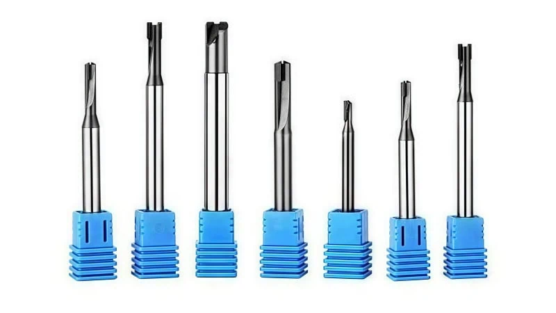
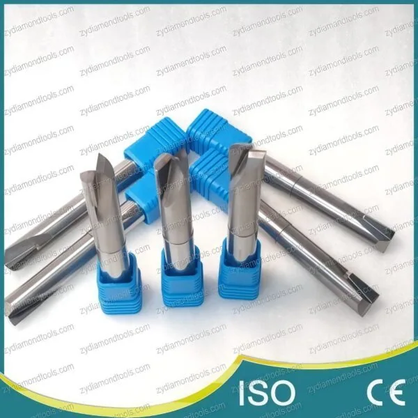
Square End Mills with Straight Flutes for Edging and Grooving
The square end mill with straight flutes is the most fundamental design in the PCD family. Visually, these tools are easy to identify. The black diamond segment is brazed parallel to the center axis of the tool. There is no twist or spiral. The cutting edge sits at a zero-degree angle relative to the shank.
In the industry, machinists often use these for 2D profiling. Because the edge is perfectly straight, the cutting mechanics are comparable to an interrupted cut performed by a shaper tool. The entire length of the cutting edge strikes the workpiece material at the exact same moment.
This “all-at-once” contact creates a high-impact cut. It effectively “chops” the material rather than slicing it. This robust geometry is excellent for simple 2D profiles, such as trimming the edge of a carbon fiber sheet or cutting a slot. However, this design generates higher radial forces that push against the tool, so it requires a rigid machine setup.
Low-Helix Shear Cutters for Reduced Vibration and Better Finish
To bridge the gap between a “chopping” straight flute and a “slicing” solid carbide spiral, manufacturers developed the low-helix shear cutter. On these tools, the diamond wafer is not brazed flat. Instead, it is angled slightly—typically between 5 and 15 degrees.
This angle changes the physics of the cut significantly. Instead of slamming into the material all at once, the angled tip enters the cut gradually. It creates a “scissoring” or shearing motion.
For a machinist, this design is the solution for vibration issues. If a straight flute tool is chattering (making a loud noise and leaving marks) on a thin aluminum wall, switching to a low-helix cutter often solves the problem. The gradual entry reduces the shock load on the spindle and the part.
Comparison: Straight Flute vs. Low-Helix Shear
| Feature | Straight Flute (0°) | Low-Helix Shear (5°-15°) |
|---|---|---|
| Contact Type | Impact (Hammers the material) | Progressive (Slices the material) |
| Cutting Force | High Radial Pressure | Reduced Radial Pressure |
| Primary Benefit | Maximum Edge Strength | Superior Surface Finish |
| Common Use | Roughing or Sheet Routing | Finishing Thin Walls |
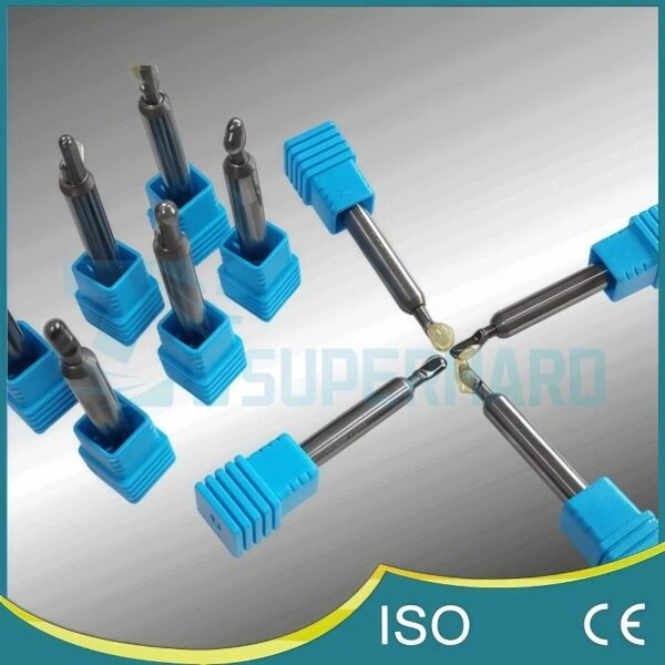
Ball Nose and Corner Radius Tools for 3D Contouring
Not all parts are flat squares. When a manufacturer needs to machine a curved mold cavity or a complex aerospace bracket, they use contouring PCD mills. These tools fall into two sub-categories:
- Ball Nose Mills: The diamond tip is shaped into a perfect half-circle (hemisphere). These are essential for 3D surfacing, where the tool must move across a sloped face without gouging the material.
- Corner Radius (Bull Nose) Mills: This is a square tool with the sharp corners ground down to a specific radius (e.g., 0.5mm or 1.0mm).
The “Bull Nose” design serves a critical structural purpose. A sharp 90-degree corner on a diamond tip is a stress concentration point. It is the weakest part of the tool and is prone to chipping if it hits a hard spot in a casting or an interruption in the cut. By adding a small radius, the tool becomes significantly stronger. For a detailed decision-making guide on selecting the correct geometry for your specific part, we recommend reading our deep dive on Flat vs. Ball Nose vs. Corner Radius PCD Mills5.

Primary Milling Applications: Specific Operations for PCD End Mills
In which specific manufacturing scenarios does a PCD end mill justify its cost by outperforming standard carbide tools?
PCD end mills are primarily deployed for high-speed peripheral profiling, face milling, and slotting operations in non-ferrous and abrasive materials. They excel at trimming composite laminates like CFRP without causing delamination, achieving mirror-quality surface finishes on aluminum and copper alloys, and maintaining precise dimensional tolerances when machining abrasive engineering plastics.
Peripheral Profiling and Trimming of Composite Sheets
The most common workload for a straight-flute PCD end mill is the peripheral profiling of composite materials. This involves cutting the outer shape of Carbon Fiber Reinforced Polymer (CFRP) or Fiberglass (GFRP) sheets.
In the aerospace and automotive industries, panels are often molded near-net shape but require final edge trimming. This is a brutal environment for standard tools. The carbon and glass fibers inside the matrix are extremely abrasive. They act like millions of tiny ceramic cutting edges attacking the tool.
A standard carbide end mill might lose its sharp cutting edge after trimming just 10 to 20 feet of fiberglass. Once the edge dulls, it stops cutting the fibers cleanly. Instead, it begins to pull and tear them. This leads to a defect known as delamination, where the layers of the composite separate.
PCD end mills solve this. Because diamond is harder than the glass or carbon fibers, the edge stays sharp for thousands of linear feet. This sharpness shears the fibers cleanly, preventing the layers from peeling apart. You can learn more about overcoming these issues in our article on PCD solutions for composite machining6.
- Operational Tip: When profiling composites, machinists typically use Climb Milling (where the cutter rotation pulls the tool into the material). This directs the cutting force inward, compressing the layers together rather than lifting them up.
High-Gloss Face Milling on Non-Ferrous Alloys
When a machinist needs to create a cosmetic, mirror-like surface on aluminum, copper, or brass, they turn to PCD end mills. This operation is often called “high-gloss finishing.”
The primary enemy in aluminum milling is the Built-Up Edge (BUE)7. Aluminum is “sticky” or gummy. During cutting, heat and pressure can cause chips to weld themselves onto the cutting edge of a carbide tool. This welded lump then drags across the workpiece, ruining the surface finish.
PCD has a distinct chemical advantage here. It has a very low coefficient of friction, and aluminum does not chemically adhere to diamond. The chips slide off the tool face effortlessly.
Surface Finish Expectations (Ra Values):
| Tool Material | Typical Surface Finish (Ra) | Visual Result |
|---|---|---|
| Standard Carbide | 0.4 µm – 0.8 µm | Visible machine lines, matte finish |
| PCD End Mill | < 0.2 µm (often < 0.1 µm) | Mirror-like reflection, no visible lines |
Note: Achieving these finishes usually requires running the spindle at maximum RPM to increase surface footage (SFM), while keeping the chip load relatively light (0.001″ – 0.003″ per tooth).
Slotting and Pocketing in Highly Abrasive Engineering Plastics
The third major application is machining pockets and slots in reinforced engineering plastics. Materials like PEEK8, Torlon, or Nylon often contain 30% or more glass fiber fill to increase their strength.
While these are “plastics,” they are incredibly damaging to cutting tools. The glass fill acts like sandpaper. When milling a slot with a carbide tool, the abrasive glass rapidly wears down the outer diameter (OD) of the cutter.
Imagine you need to mill a slot that is exactly 0.250 inches wide. You start with a brand-new 0.250-inch carbide end mill. After cutting just 50 parts, the abrasive glass might wear the tool diameter down to 0.248 inches. Now, your slot is too narrow, and the parts are out of tolerance (scrap).
PCD end mills maintain their diameter almost indefinitely in these materials. A single tool can machine thousands of slots without losing its size. This stability is critical for automated production runs where an operator cannot stop every hour to check if the tool has shrunk.
Conclusion
PCD end mills represent a critical intersection of material science and tool geometry. While their brazed construction and straight-flute or low-shear designs differ significantly from traditional solid carbide spirals, these features are purposeful adaptations to the extreme hardness of diamond.
By understanding the unique “what” of PCD end mills—specifically their hybrid construction and distinct classifications like straight flute versus low-helix shear—manufacturers can unlock significant productivity gains. Whether you are aiming for a mirror finish on an aluminum prototype or preventing delamination on aerospace composites, selecting the correct PCD end mill geometry9 is the key to consistent, high-quality machining.
References
- PCD Tools for Aluminum1 – ZYDiamondTools guide to maximizing performance when machining aluminum alloys.
- Polycrystalline Diamond (PCD)2 – ScienceDirect topic page explaining the material properties and synthesis of PCD.
- Tungsten Carbide3 – Wikipedia entry detailing the composition and applications of tungsten carbide in tooling.
- Electrical Discharge Machining (EDM) for PCD4 – Detailed explanation of how EDM is used to shape PCD cutting edges.
- Choosing Between Flat, Ball Nose, and Corner Radius5 – ZYDiamondTools comparative guide on selecting the best geometry for specific milling operations.
- PCD Solutions for Composite Machining6 – Case studies and strategies for machining composite materials with PCD.
- Built-Up Edge (BUE)7 – Wikipedia article explaining the causes and effects of built-up edge in machining.
- PEEK Plastic8 – Wikipedia overview of Polyether ether ketone, a high-performance engineering thermoplastic.
- Selecting and Optimizing PCD End Mills9 – ZYDiamondTools article providing best practices for tool selection and milling strategies.


