-
Whatsapp: +86 13526572721
-
Email: info@zydiamondtools.com
-
Address: AUX Industrial Park, Zhengzhou City, Henan Province, China
-
Whatsapp: +86 13526572721
-
Email: info@zydiamondtools.com
-
Address: AUX Industrial Park, Zhengzhou City, Henan Province, China

Solving Hydraulic Valve Interrupted Cuts and Cylindricity Issues with PCBN
What are the most effective PCBN strategies for overcoming interrupted cuts in hydraulic valve bodies and ensuring cylindricity in hardened spools?
To successfully machine hydraulic valves, manufacturers must utilize PCBN grades with specific edge preparations to resist shock in interrupted valve body cuts. Conversely, for hardened spools, achieving micron-level cylindricity requires minimizing passive cutting forces through reduced nose radii and strictly managing thermal expansion during dry turning.
Stabilizing PCBN Tool Life Across Valve Body Oil Galleries
How do you prevent PCBN inserts from breaking when machining hydraulic valve bodies with interrupted cuts?
To stabilize tool life in interrupted cuts1, you must select a high-content PCBN grade (typically 85-90% CBN) paired with a negative edge preparation, such as a T-land. This combination increases fracture toughness and redirects cutting forces into the bulk of the insert, preventing the cutting edge from chipping when it impacts cross-holes or oil galleries.
Selecting Tougher PCBN Grades to Resist Shock Loading at Cross Holes
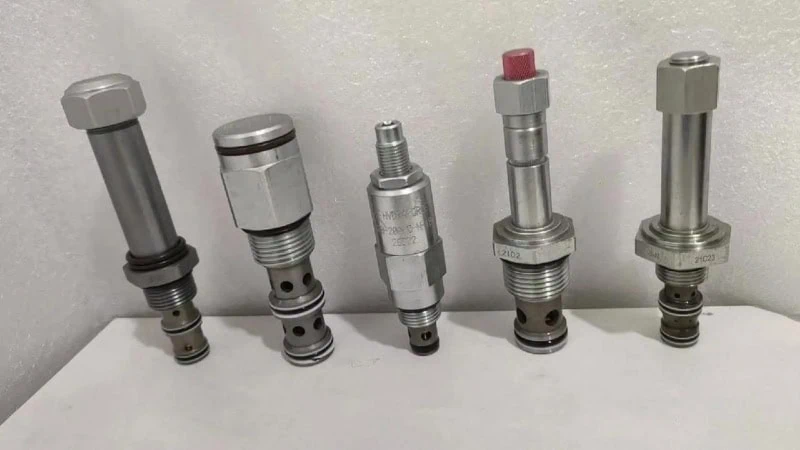
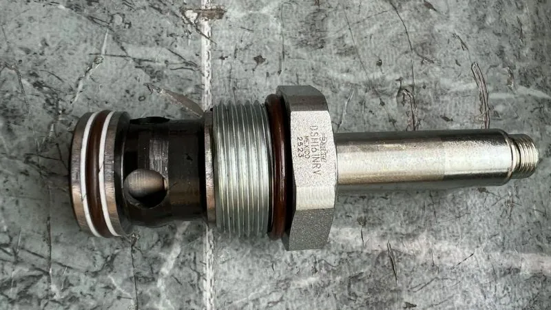
Machining hydraulic valve bodies presents a unique challenge compared to smooth turning. The main issue is the internal geometry. Valve bodies contain numerous cross-holes and oil galleries. As the tool passes these voids, the cut is interrupted. The tool exits the metal and re-enters with a sudden impact. This shock can instantly shatter a standard insert.
To fix this, you must choose the right PCBN composition. Not all PCBN is the same. It varies based on the percentage of Cubic Boron Nitride2 (CBN) particles and the binding material used.
- Low-Content PCBN (50-65% CBN): These are excellent for continuous cuts on hardened steel. However, they are often too brittle for the heavy interruptions found in cast iron valve bodies.
- High-Content PCBN (85-90% CBN): This is the industry standard for interrupted cuts. The high concentration of CBN particles creates a much stronger structure. It acts like a shock absorber.
Think of this like choosing a milling cutter. You would not use a delicate, high-speed finishing end mill to rough out an uneven casting surface. You would use a heavy-duty face mill designed to take a beating. Similarly, for valve bodies with holes, you need a high-content “roughing” grade, even if you are doing a finishing pass.
Binder Selection Matters
The material holding the CBN particles together (the binder) also changes performance. Metallic binders generally offer better toughness than ceramic binders. For severe interruptions in hydraulic components, metallic binders help stop cracks from spreading.
Comparison of PCBN Grades for Valve Bodies
| Feature | Low-Content PCBN | High-Content PCBN |
|---|---|---|
| CBN Percentage | 50% – 65% | 85% – 95% |
| Primary Strength | Wear Resistance (Chemical) | Impact Resistance (Physical) |
| Best Application | Hardened Steel Spools (Continuous) | Cast Iron Valve Bodies (Interrupted) |
| Reaction to Shock | Prone to Chipping | Resists Chipping |
Optimizing Edge Preparation to Protect the PCBN Cutting Lip During Entry and Exit
Even the toughest grade will fail if the edge geometry is wrong. A “sharp” cutting edge is the weakest point on an insert. When a sharp edge hits the side of an oil gallery hole, the force is concentrated on a tiny area. This causes the tip to snap off.
To protect the tool, we use Edge Preparation3. This usually involves adding a chamfer, known in the industry as a T-land, or honing the edge.
How T-lands Work
A T-land is a small angle ground onto the cutting edge. It changes the direction of the cutting forces.
- Sharp Edge: Forces push directly back against the brittle tip.
- T-land Edge: Forces are directed downward into the main body of the insert.
The insert body is much stronger than the tip. By redirecting the force, the tool can survive the “hammering” effect of entering and exiting the oil holes hundreds of times.
Standard Recommendations
For cast iron valve bodies with average interruptions, a standard recommendation is often a 0.15mm x 20° T-land. However, if the cut is heavily interrupted, you may need a larger angle.
- Light Interruption: 0.10mm x 15°
- Heavy Interruption (Large Oil Ports): 0.20mm x 25°
Note: Different PCBN manufacturers use different coding systems for edge prep (e.g., some include the hone size in the dimension, others do not). Always verify the specific T-land dimensions with your supplier to match your specific cutting conditions.
Case Study: Reducing Insert Breakage in Cast Iron Valve Bodies with Heavy Interruptions
A hydraulic manufacturer faced inconsistent tool life while machining a G2500 Grey Cast Iron directional control valve body. The operation involved finish turning the main bore, which intersected with four large radial oil galleries.
The Problem
The manufacturer was using a coated PCBN insert originally designed for hardened steel. The tool life was unpredictable.
- Average life: 15 parts per edge.
- Failure mode: The insert corner would often break catastrophically upon hitting the second oil port. This forced the operator to stop the machine frequently to change inserts.
The Solution
The engineering team analyzed the failure and made two key changes:
- Grade Change: They switched to a solid PCBN grade with 90% CBN content and a metallic binder.
- Edge Prep Adjustment: They moved from a light hone to a 0.2mm x 20° negative T-land.
The Results
The new setup handled the mechanical shock significantly better. The tool no longer chipped at the gallery edges.
- Old Tool Life: 15 parts/edge (unstable).
- New Tool Life: 120 parts/edge (consistent).
- Efficiency: Machine downtime for tool changes was reduced by 85%.
By prioritizing toughness over pure hardness, the manufacturer solved the interruption problem without changing the cycle time or the machine setup.

Achieving Micron-Level Cylindricity in Hardened Spools
Hydraulic spools demand extremely tight geometric tolerances. How can manufacturers maintain cylindricity when hard turning4 these long, slender components?
To ensure dimensional accuracy in hardened spools, manufacturers must minimize passive cutting forces by utilizing PCBN inserts with a reduced nose radius (typically 0.2mm to 0.4mm) and optimizing the entry angle. Furthermore, controlling thermal expansion through air cooling and implementing systematic tool wear offsets are critical strategies to prevent taper and diameter deviations during dry machining.
Managing Passive Force Deflection in High-Aspect-Ratio Spools
Hydraulic valve spools are often long and thin. In machining terms, they have a high length-to-diameter (L/D) ratio. When you apply the cutting tool to a spool with an L/D ratio greater than 10:1, the workpiece acts like a flexible beam. It naturally wants to bend away from the tool. This phenomenon is known as “deflection” or “push-off.”
If the spool bends during the cut, the resulting part will be barrel-shaped or tapered. The middle of the spool will have a larger diameter than the ends because the part deflected away from the cutter at the point of lowest rigidity.
The Role of Passive Force
In PCBN hard turning, the passive force (thrust force) is the enemy of cylindricity. It is the force pushing directly perpendicular to the workpiece axis. To fix this, you must reduce the contact area between the tool and the part.
- Nose Radius Selection: A large nose radius (like 0.8mm) creates high passive pressure. For slender spools, you should switch to a 0.2mm or 0.4mm nose radius. This acts like a sharper point, cutting cleaner with less “push.”
- Approach Angle: Using a tool holder with an approach angle closer to 90° (or 0° lead angle) directs the cutting forces axially (along the length of the part) rather than radially (into the part). This reduces the tendency of the spool to bend.
Impact of Nose Radius on Passive Force
| Nose Radius | Passive Force Level | Risk of Deflection | Best Application |
|---|---|---|---|
| 0.8mm | High | High | Rigid, large diameter parts |
| 0.4mm | Medium | Moderate | Standard valve spools |
| 0.2mm | Low | Low | Long, thin spools (High L/D) |
Compensating for PCBN Flank Wear to Maintain Micron-Level Tolerances
In hydraulic assemblies, the clearance between the spool and the valve body is often less than 3 to 5 microns. Therefore, even microscopic tool wear changes the part diameter enough to cause leakage or seizing.
PCBN tools wear differently than carbide tools. They develop flank wear5 relatively quickly during the “break-in” period and then stabilize. As the flank wears, the cutting edge effectively recedes from the workpiece.
The “Step-Correction” Strategy
You cannot wait for the tool to fail. You must predict the wear. If a PCBN edge recedes by 5 microns, your turned diameter will increase by 10 microns (on diameter).
Experienced machinists use a “step-correction” method:
- Establish a Wear Rate: Run a test batch. If the diameter grows by 2 microns every 10 parts, you know the wear rate.
- Programmed Offsets: Do not rely on manual measurement for every part. Program the machine to automatically adjust the tool offset (e.g., -2 microns) after every 10 cycles.
Example: The 5-Micron Rule
In high-precision spool production, a common industry standard is to index (rotate) the PCBN insert once flank wear reaches 0.1mm (100 microns). Note that this limit is specifically for maintaining size; the tool may still be sharp enough to cut, but the cutting pressure will have risen enough to cause the deflection issues discussed in the previous section.
Solving Thermal Expansion Issues During Continuous Dry Turning
Hard turning with PCBN is almost always performed dry (without coolant). This is because PCBN is sensitive to thermal shock; the rapid heating and cooling from coolant can cause the insert to crack.
However, dry machining generates intense heat. While 80% of this heat should leave with the chip, the remaining 20% enters the workpiece.
The “Shrinkage” Problem
Steel expands when hot. If you machine a spool to the correct diameter while it is hot (e.g., 60°C), it will shrink when it cools down to room temperature (20°C).
- The Result: The cooled part will be undersized.
- The Scale: For a 20mm diameter steel spool, a 40°C temperature rise can change the diameter by nearly 10 microns. This completely consumes your tolerance band.
Thermal Management Solutions
To combat this without using flood coolant, consider these industry-specific techniques:
- Cold Air Gun: Use a vortex tube to blast sub-zero air onto the part immediately after the cut. This removes residual heat without the thermal shock of liquid coolant.
- Tailstock Pressure Control: As the part heats up, it expands in length. This is due to thermal expansion6. If the tailstock is too rigid, the expanding part will bow (buckle), destroying cylindricity. Use a programmable or hydraulic tailstock that maintains constant force, allowing for slight thermal expansion without bending the part.
- Temperature-Compensated Gauging: If you use in-process gauging (probes), ensure the probing system accounts for the part’s temperature. It is safer to measure the part only after it has normalized to ambient temperature.
Minimizing Burr Formation at Port Breakouts
Why do burrs form at the edges of valve ports during hard turning, and how can you stop them?
Burrs occur when the cutting tool pushes material over the edge of a hole rather than shearing it off cleanly, a process known as plastic deformation. To minimize this, you must use PCBN inserts with a sharper edge preparation (reduced hone size), maintain a light depth of cut to prevent material rollover, and prioritize standard nose geometries over wiper inserts to reduce radial pressure at the breakout point.
The Role of PCBN Edge Sharpness in Clean Hole Exits
The primary cause of burrs in hydraulic valves is “plowing.” If your cutting tool is blunt, it acts like a bulldozer. Instead of cutting the metal, it pushes the metal ahead of it. When the tool reaches the edge of an oil port or cross-hole, there is no material left to support the cut. Consequently, that pushed metal simply folds over into the hole, creating a burr.
To fix this, you need to look at the Edge Preparation (Hone).
In the previous section, we discussed using a T-land (chamfer) to protect the tool from breaking. However, there is a trade-off. A large T-land is blunt. It protects the tool but creates bigger burrs. For clean hole exits, you need a sharper edge.
Finding the Balance
You generally want to use the lightest hone possible that still survives the interrupt.
- Heavy Hone (e.g., 25-30 microns): Great for tool life, but pushes a large burr into the port.
- Light Hone (e.g., 10-15 microns): Shears the metal cleanly, leaving almost no burr, but is more fragile.
Think of this like a generic drilling operation. A dull drill bit pushes a cap of metal out the back of a plate (the exit burr). A sharp drill bit cuts cleanly all the way through. In valve turning, your PCBN insert needs to act like that sharp drill bit at the exact moment it crosses the port.
Note: Measurement standards for edge hones vary significantly between manufacturers (e.g., “E01” vs “S01”). Ensure you are comparing the actual micron measurement of the hone rather than just the code.
Adjusting Depth of Cut to Reduce Plastic Deformation at Edges
The Depth of Cut (DOC) is another critical factor. It controls how much material the tool is trying to remove at once.
If the DOC is too heavy, the cutting forces are high. When the tool reaches the breakout point (the edge of the hole), these high forces cause the remaining thin wall of metal to collapse and hinge over into the hole. This is often called plastic deformation7 or a “rollover burr.”
The “Light Pass” Strategy
To prevent this, experienced machinists use a multi-pass strategy. They leave a very small amount of material for the final finish pass.
- Roughing Pass: Removes bulk material.
- Finish Pass: Removes only 0.05mm to 0.10mm (on radius).
By taking such a light cut, the cutting pressure is extremely low. The tool slices through the final layer without enough force to bend the metal over the edge.
Relationship Between DOC and Nose Radius
A general industry rule for minimizing burrs is that your Depth of Cut should be significantly less than your tool’s nose radius. If you use a 0.4mm nose radius, a 0.1mm DOC ensures the cutting action happens on the curved part of the nose, effectively “thinning” the chip as it exits the cut.
Comparing Wiper vs Standard PCBN Geometries for Port Quality
Wiper inserts are famous in the turning industry for generating mirror-like surface finishes at high feed rates. However, when machining hydraulic valves with cross-holes, Wiper inserts can be problematic.
The Wiper Problem
A Wiper insert has a small “flat” section ground onto the nose. This flat smooths out the peaks on the surface of the part. However, this flat section also creates a longer line of contact between the tool and the metal.
- Increased Contact: More contact equals more “rubbing” pressure.
- Radial Force: This rubbing pushes hard against the part surface.
When a Wiper insert passes over a hole, that extra pressure pushes material into the hole more aggressively than a standard round insert.
The Standard Solution
For valve bodies where port cleanliness is critical (to avoid stuck spools later), a Standard ISO Nose Radius (like a standard CNGA 120404) is often superior.
- Standard Radius: Point contact. Low pressure. Clean exit.
- Wiper Radius: Line contact. High pressure. Potential for burrs.
Selection Guide for Valve Breakouts
| Geometry Type | Cutting Pressure | Burr Risk | Recommended For |
|---|---|---|---|
| Standard Radius | Low | Low | Valve bodies with many cross-holes |
| Wiper Geometry | High | High | Solid shafts without interruptions |
Therefore, if you are struggling with burrs at the port edges, try removing the Wiper insert and switching to a standard radius tool. You may have to slow down your feed rate to maintain the surface finish, but you will eliminate the costly manual deburring operations.
Surface Integrity Requirements for Spool Sliding and Sealing
Beyond dimensional accuracy, the surface quality of the spool is vital for lubrication and seal longevity. How do you balance these factors?
To ensure proper surface integrity, manufacturers must prevent “white layer” formation by replacing worn PCBN inserts before flank wear exceeds 0.2mm. Additionally, optimizing feed rates to create distinct spiral grooves allows for oil retention, ensuring lubrication while maintaining a surface roughness (Ra) typically between 0.2µm and 0.4µm to prevent seal abrasion.
Preventing White Layer Formation Caused by Worn PCBN Edges
In hydraulic applications, the surface of the spool must be hard but not brittle. However, aggressive hard turning can damage the metal surface invisibly. This damage is called the “White Layer.”
What is the White Layer?
The white layer is a microscopic zone on the surface of the part. It is extremely hard and brittle. Under a microscope, it looks white because the structure has changed. This happens when the cutting temperature gets too high. The metal momentarily melts or changes phase, then rapidly quenches (cools) itself.
The Danger of Dull Tools
A sharp PCBN tool cuts the metal cleanly. A worn PCBN tool rubs the metal. This rubbing creates intense friction heat.
- Sharp Edge: Heat goes into the chip (good).
- Worn Edge: Heat goes into the part (bad).
If the Flank Wear (VB) on your insert exceeds 0.15mm to 0.20mm, the risk of white layer formation skyrockets. Although the tool might still cut to size, the surface it leaves behind is compromised. This brittle layer can flake off (spall) during operation. These tiny metal flakes then contaminate the hydraulic oil and destroy the pump.
Generating Specific Tribological Patterns for Oil Retention
Tribology is the science of friction and lubrication. In hydraulic valves, smoother is not always better.
If a spool is perfectly smooth (like a mirror), it can stick to the valve body. This is known as “stiction” or the “gauge block effect.” There is no room for oil to sit between the metal surfaces.
Turning vs. Grinding
- Grinding: Creates a random, chaotic surface texture.
- Hard Turning: Creates a structured, spiral surface texture.
The spiral groove left by a PCBN tool acts like a microscopic reservoir. It holds hydraulic fluid. This ensures that the spool floats on a thin film of oil rather than rubbing metal-on-metal. This is critical for the longevity of the valve.
Controlling the Pattern
You can control this oil retention capability by adjusting your turning parameters. The goal is to create a “bearing area curve” that supports the load but leaves valleys for the oil. Many hydraulic engineers now prefer the deterministic pattern of hard turning over grinding because it provides more consistent lubrication properties.
Balancing Feed Rate and PCBN Nose Radius for Seal Compatibility
While metal-to-metal sliding needs oil pockets, the spool also slides against soft rubber or PTFE seals. If the surface is too rough, it acts like a file. It will shred the seal, causing external leakage.
You must balance the Feed Rate (fn) and the Tool Nose Radius (r).
The Geometry of Roughness
The theoretical surface roughness in turning is determined by a simple geometric relationship. A larger nose radius or a lower feed rate smooths out the “peaks” of the spiral groove.
- High Feed / Small Radius: Creates sharp, high peaks. These cut seals.
- Low Feed / Large Radius: Creates low, gentle waves. These are seal-friendly.
Recommended Parameters for Sealing Surfaces
To achieve the standard industry target of surface roughness (Ra)8 0.2µm – 0.4µm without polishing, consider these combinations:
| Desired Surface Finish (Ra) | Nose Radius (mm) | Recommended Feed Rate (mm/rev) | Result on Seals |
|---|---|---|---|
| Ra > 0.8µm | 0.4 | > 0.15 | Abrasive (Risk of leakage) |
| Ra 0.4µm | 0.4 | 0.08 – 0.10 | Good (Standard balance) |
| Ra 0.2µm | 0.8 | 0.05 – 0.07 | Excellent (But high tool pressure) |
If you use a Wiper insert (discussed in previous sections), you can double the feed rate while maintaining the same roughness. However, for standard inserts, keeping the feed rate below 0.10mm/rev is usually necessary to protect sensitive O-rings and lip seals from premature wear.
Conclusion
Transitioning from grinding to PCBN hard turning offers immense efficiency gains for hydraulic valve manufacturing, but it requires precision. By selecting high-content PCBN grades for interrupted valve bodies and managing passive forces on slender spools, manufacturers can achieve superior cylindricity and surface integrity. Whether you are battling broken inserts at cross-holes or fighting thermal expansion, the right PCBN strategy is the key to consistent quality.
References
- Interrupted Cuts1 – ZYDiamondTools blog post on overcoming interrupted machining challenges.
- Cubic Boron Nitride2 – Wikipedia overview of CBN material properties and applications.
- Edge Preparation3 – ZYDiamondTools guide to the importance of edge radiusing and honing.
- Hard Turning Explained4 – ZYDiamondTools article comparing hard turning processes to grinding.
- Flank Wear5 – ScienceDirect technical overview of tool wear mechanisms.
- Thermal Expansion6 – Engineering Toolbox data on thermal expansion coefficients for metals.
- Plastic Deformation7 – ScienceDirect topic on plastic deformation of materials during machining.
- Surface Roughness (Ra)8 – Wikipedia guide to surface roughness parameters.


