-
Whatsapp: +86 13526572721
-
Email: info@zydiamondtools.com
-
Address: AUX Industrial Park, Zhengzhou City, Henan Province, China
-
Whatsapp: +86 13526572721
-
Email: info@zydiamondtools.com
-
Address: AUX Industrial Park, Zhengzhou City, Henan Province, China

Rough Boring vs. Finish Boring: How to Choose the Right Process for Optimal Results?
When it comes to creating precise holes in machining, what is the real difference between rough boring and finish boring?
Rough boring is a high-speed machining process focused on removing the maximum amount of material to quickly enlarge a pre-existing hole to near its final size. In contrast, finish boring is a slow, high-precision process focused on achieving the exact final diameter, tight geometric tolerances, and a smooth surface finish. They are not interchangeable processes but rather two essential, sequential stages of a complete boring operation.
What Are the Primary Goals of Each Boring Process?
So, what is the fundamental purpose of rough boring compared to finish boring?
The primary goal of rough boring is to remove a large volume of material as quickly as possible, creating a hole that is close to the final desired size. In contrast, the main goal of finish boring is to achieve the final, exact hole size with a high-quality surface finish and precise geometric accuracy.
Rough Boring: Maximizing Material Removal Rate (MRR)
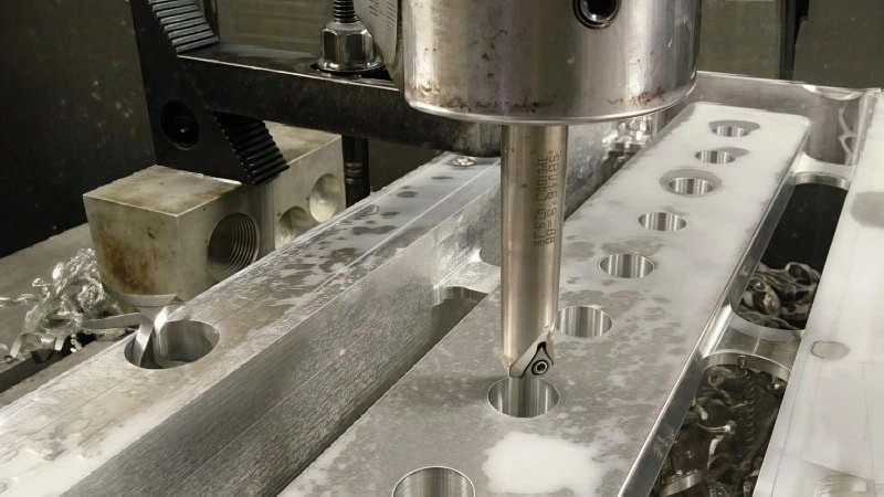
Think of rough boring as the heavy-lifting phase of creating a hole. Its main job is not to be pretty or perfect but to be fast and powerful. The single most important objective here is to maximize the Material Removal Rate (MRR)1.
Essentially, MRR measures how much material is cut away from a workpiece in a given amount of time. For a manufacturing facility, a higher MRR means the initial stage of machining is completed faster, which directly saves time and reduces costs. This process takes a pre-existing hole, perhaps from drilling or casting, and quickly enlarges it.
Therefore, the hole left after rough boring is intentionally oversized slightly to leave material for the finishing step. The walls of the hole will feel coarse to the touch and will have visible tool marks. This is a planned and accepted outcome because the ultimate goal here is pure efficiency.
Finish Boring: Achieving Precision and Surface Quality
After the heavy work of rough boring is done, finish boring comes in to perform the delicate, high-precision work. If rough boring is the excavator, finish boring is the skilled artisan with a fine-toothed file and a laser measuring tool. The goals here completely shift from speed to accuracy.
The two primary objectives are:
- Precision: This means achieving the exact target dimension specified in an engineering blueprint. We aren’t just getting close; we are aiming for perfection. For example, in an engine block, the cylinder bore where a piston moves must be machined to an incredibly tight tolerance. If the specification is 86.00 mm, finish boring aims to hit that dimension with an error of only a few micrometers (a human hair is about 70 micrometers thick). This level of dimensional accuracy is critical for the engine’s performance and efficiency.
- Surface Quality: This refers to creating a very smooth surface inside the hole, often measured by a value called “Ra.” A low Ra value means the surface is extremely smooth, sometimes almost like a mirror. Why does this matter?
- For Sealing: In a hydraulic valve, a perfectly smooth surface allows O-rings and seals to sit flawlessly, preventing leaks under high pressure.
- For Reducing Friction: In the engine cylinder example, a smooth wall reduces friction with the piston rings, which means less wear, less heat, and more power.
To achieve this, finish boring removes only a tiny amount of material with each pass. It is a much slower and more controlled process, but it is absolutely essential for creating high-performance, reliable parts.

How Do Their Technical Specifications and Results Compare?
So, how do the actual numbers and settings differ between rough and finish boring?
Rough boring uses aggressive cutting parameters (high feed rate and deep cuts) to achieve wider dimensional tolerances, typically from IT9 to IT11, resulting in a coarse surface finish. In contrast, finish boring uses delicate parameters (low feed rate and shallow cuts) to achieve tight tolerances, from IT6 to IT8, resulting in a very smooth, high-quality surface finish.
Dimensional Tolerance (IT Grades)
Imagine trying to fit a key into a lock. If the keyhole is made with a wide tolerance, it’s a bit loose and several slightly different keys might fit poorly. If it’s made with a tight tolerance, only the one, perfectly sized key will fit exactly as it should. In manufacturing, dimensional tolerance is this acceptable range of variation for a specific size.
We measure this using a standardized system of International Tolerance (IT) Grades2. The rule is simple: the lower the IT number, the tighter the tolerance and the more precise the part.
Here’s how the two processes typically compare:
| Process | Typical IT Grade | Meaning |
|---|---|---|
| Rough Boring | IT9 – IT11 | Wider tolerance; less precise. Perfect for the initial stage. |
| Finish Boring | IT6 – IT8 | Tight tolerance; very precise. Essential for the final product. |
Achieving a specific IT grade isn’t just about the process, however. It also depends heavily on the rigidity of the machine, the quality of the boring bar3, and the material being cut.
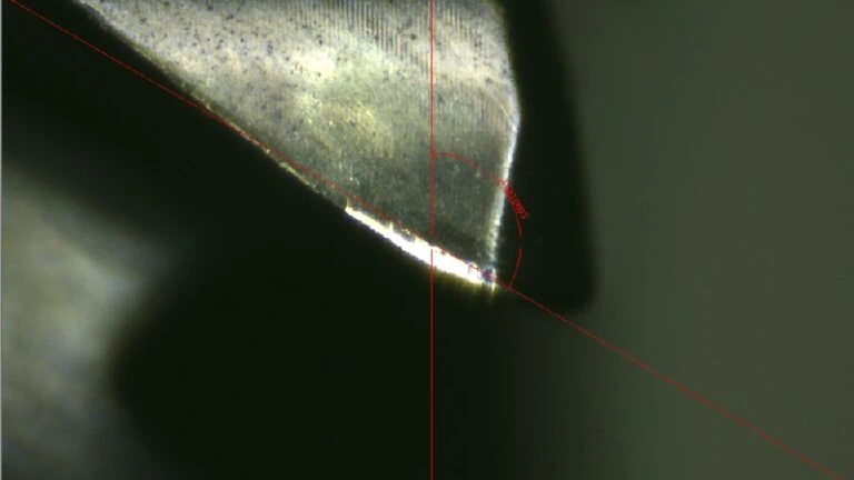
Surface Finish (Ra Values)
What does the inside of the hole actually feel like? This is its surface finish. Think of the difference between a bumpy gravel road and a smooth racetrack. We measure this smoothness using a value called Ra (Roughness Average)4. A low Ra value means the surface is very smooth, while a high Ra value means it’s coarse.
The difference in results between the two processes is significant:
| Process | Typical Ra Value (micrometers, μm) | Analogy |
|---|---|---|
| Rough Boring | 6.3 – 25 μm | Feels coarse, like fine-grit sandpaper. |
| Finish Boring | 0.2 – 1.6 μm | Feels very smooth, sometimes almost like glass. |
A smooth surface is not just for looks. As mentioned before, it’s critical for parts that need to form a perfect seal or for components where friction must be minimized, like in hydraulic systems or engine cylinders.
Typical Cutting Parameters (Feed, Speed, Depth of Cut)
To get these vastly different results, we have to control the machine’s settings, known as cutting parameters. The three most important ones are:
- Depth of Cut: How deep the cutting tool slices into the material on each pass.
- Feed Rate: How quickly the tool travels along the length of the hole.
- Cutting Speed: How fast the workpiece or the tool is rotating.
The strategy for each process is a complete opposite of the other, each designed to achieve its specific goal.
| Parameter | Rough Boring | Finish Boring |
|---|---|---|
| Depth of Cut | High. To remove a lot of material at once. | Low. To “shave” off a tiny, precise layer. |
| Feed Rate | High. To move through the hole quickly. | Low. To create a smooth, consistent surface. |
| Cutting Speed | Lower. To manage heat and tool pressure during deep cuts. | Higher. To help produce a finer surface finish. |
It is crucial to understand that these parameters are not universal constants. The ideal settings can change significantly based on the workpiece material (e.g., aluminum requires different parameters than hardened steel), the type of cutting insert being used (PCD, CBN, or Carbide), and the specific machine’s power and stability.
Professional Tip: Always use the cutting parameter recommendations from your tooling supplier as a starting point. They provide proven data for their tools in various materials, which can save you time and prevent tool damage.
What Kind of Tooling Is Required for Each Operation?
So, what are the main differences in the tools used for rough and finish boring?
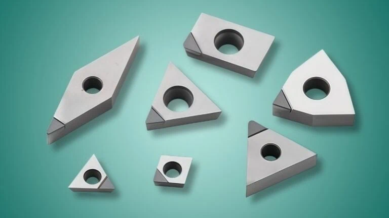
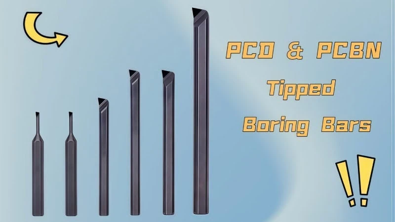
Rough boring requires strong, rigid tools, often with multiple cutting edges (inserts), designed to withstand heavy forces and maximize material removal. In contrast, finish boring uses highly precise, often single-point, adjustable tools designed to achieve exacting dimensions and a smooth surface. The cutting edge material—typically Carbide, CBN, or PCD—is then selected based on the workpiece material.
Rough Boring Tools: Built for Rigidity and Efficiency
The entire design of a rough boring tool is focused on two things: strength and speed.
The primary characteristic of a rough boring tool is its rigidity. Because it takes deep, aggressive cuts, the tool is subjected to immense cutting forces. To handle this, these tools are:
- Built to be Sturdy: They have thick, solid bodies to resist bending and chattering under pressure. A tool that vibrates, even slightly, cannot cut effectively.
- Designed for Efficiency: Many rough boring heads are engineered to use two (or sometimes more) cutting inserts simultaneously. This is often called a twin-cutter or multi-cutter design. Why? It effectively doubles the material removal rate, getting the job done in half the time compared to a single-insert tool.
In short, every feature of a rough boring tool is optimized to remove as much material as possible, as quickly as possible, preparing the workpiece for the next stage.
Finish Boring Tools: Designed for High-Precision Adjustment
The design philosophy of a finish boring tool shifts completely from power to precision. The most critical feature is its ability to be adjusted with incredible accuracy.
These tools feature micro-adjustment mechanisms. This is often a small, finely threaded dial or screw built directly into the tool head. By turning this dial, an operator can expand or retract the cutting insert by just a few micrometers (μm) at a time. This fine-tuning capability is what allows machinists to achieve the extremely tight dimensional tolerances (like IT6) required for high-performance parts.
Furthermore, finish boring tools typically use a single cutting point. While this slows the process down compared to a twin-cutter roughing tool, it provides a significant advantage in quality. Using a single “blade” results in a more consistent cutting action, which is essential for producing the ultra-smooth surface finishes that define a finished part.
Selecting the Right Cutting Edge Material (PCD, CBN, Carbide)
The tool body holds the cutting insert, but the insert itself does all the work. Choosing the right material for this cutting edge is just as important as choosing the right tool body. There is no single “best” material; the optimal choice depends entirely on what material you are cutting.
Here is a simple breakdown of the three most common advanced materials:
| Cutting Material | Primarily Used For | Key Advantage |
|---|---|---|
| Coated Carbide | General-purpose steels, stainless steels, cast iron. | Versatile and cost-effective “workhorse” for many applications. |
| CBN5 (Cubic Boron Nitride) | Hardened steels (>45 HRC), hard cast irons, superalloys. | Maintains hardness at very high temperatures for cutting hard metals. |
| PCD6 (Polycrystalline Diamond) | Non-ferrous metals (aluminum, copper) & abrasive materials. | Extreme hardness provides the longest tool life and best finish. |
Coated Carbides: The Versatile Workhorse
Carbide inserts are the most common and versatile option in machining. With various modern coatings, they can successfully cut a huge range of materials, especially different types of steel. They offer a great balance of performance and cost for many general boring applications.
CBN (Cubic Boron Nitride): The Specialist for Hard Metals
When you need to machine materials that are already very hard, you need something even harder. CBN, second only to diamond in hardness, is the perfect tool for the job. It excels at boring hardened steels, tough cast irons, and other difficult-to-cut ferrous metals because it stays hard even when it gets very hot from the friction of cutting.
PCD (Polycrystalline Diamond): The Champion for Non-Ferrous & Abrasives
PCD is the pinnacle of cutting material hardness. This makes it the ideal choice for materials that cause other inserts to wear out quickly. Its main applications are:
- Non-Ferrous Metals: It provides an exceptional, mirror-like surface finish and incredibly long tool life when boring aluminum (especially high-silicon aluminum), copper, brass, and bronze.
- Abrasive Materials: It is the go-to solution for cutting tough, abrasive composites like carbon fiber reinforced polymer (CFRP), fiberglass, and metal matrix composites (MMCs).
Important Note: PCD should not be used to cut steel or other iron-based metals. At the high temperatures generated during cutting, the carbon in the diamond has a chemical reaction with the iron in the steel, causing the tool to degrade very quickly. Always consult your tooling supplier to confirm the best insert material for your specific job.
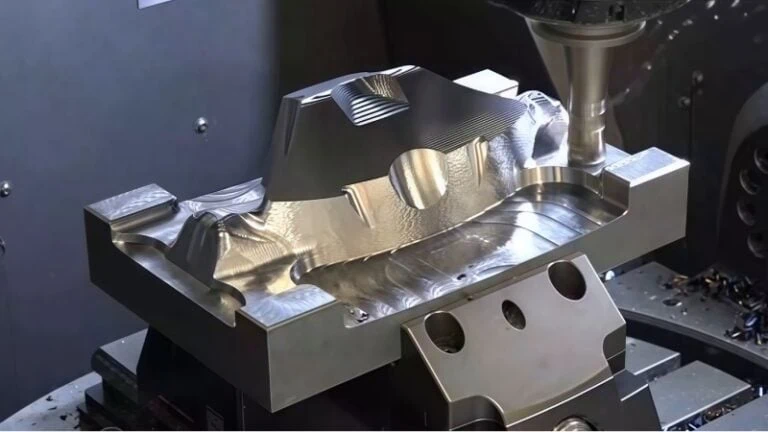
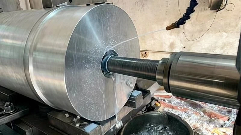
Integrating Boring Processes into Your Workflow
Understanding when and how to use these two processes in a real-world scenario is key to achieving consistent results.
Rough and finish boring are almost always used together as sequential steps in a precision machining workflow. Rough boring is the first machining step used to quickly open up a pre-existing hole to near its final size. Finish boring is the final machining step, used immediately after roughing, to bring the hole to its exact dimensional and surface finish specifications.
The Standard Machining Workflow: From Drilled Hole to Finished Bore
Creating a precision hole is a multi-stage journey. You can’t simply take a solid piece of metal and create a perfect hole in a single step. Instead, it’s a systematic process where each step prepares the workpiece for the next, ensuring the final result is flawless.
The typical workflow looks like this:
- Starting Hole Creation: The process begins with a basic hole, usually made by drilling or created during the casting of the part. This initial hole is typically inaccurate in size, position, and straightness.
- Rough Boring: This is the first corrective step. The rough boring tool enters the starting hole and quickly enlarges it, removing the bulk of the excess material. This operation corrects major positional errors and creates a more uniform hole, leaving behind a small, consistent amount of material for the final step.
- Finish Boring: This is the final and most critical machining stage. The finish boring tool enters the roughed hole and takes one or more light, precise passes. It shaves off the last bit of material to bring the hole to its exact target diameter, geometric tolerance, and smooth surface finish.
- (Optional) Honing or Burnishing: For the absolute highest levels of precision, such as in fuel injectors or high-performance hydraulic systems, further processes like honing7 might be used after finish boring to achieve an even finer surface.
Application Examples: Engine Blocks, Hydraulic Valves, and Gearboxes
Understanding the workflow is helpful, but seeing where it’s applied in real-world products makes the concepts clear. These processes are essential in countless industries where precision is not optional.
Engine Blocks
In an automotive engine block, the cylinder where the piston moves is a critical component.
- Rough Boring is used on the raw engine casting to quickly machine the cylinders close to their final diameter.
- Finish Boring then provides the final, perfectly round, and smooth surface. This precision ensures the piston rings can form a tight seal to contain combustion pressure, maximizing engine power and efficiency.
Hydraulic Valves
The body of a hydraulic valve contains intricate pathways where spools must slide back and forth to direct fluid flow.
- Rough Boring carves out these internal pathways from a solid block of steel or aluminum.
- Finish Boring machines the spool bores to an exact size and an extremely smooth finish. This allows the spools to move freely while preventing high-pressure fluid from leaking past the seals, which is critical for the valve to function reliably.
Gearboxes
The housing of a gearbox must hold shafts and bearings in perfect alignment. Any error can lead to rapid wear and catastrophic failure.
- Rough Boring is used to create the initial pockets where the bearings will sit.
- Finish Boring ensures these pockets have the precise diameter for a bearing to be press-fit securely and are perfectly concentric and parallel to each other. This guarantees the gears will mesh correctly and the bearings will last.
Making the Final Choice: A Decision-Making Checklist
Deciding between rough and finish boring isn’t an “either/or” choice—it’s about knowing when to use each in the proper sequence. Ask yourself these questions to solidify your strategy for any boring operation.
- What is my primary goal right now?
- If the answer is “remove a lot of material quickly,” you need Rough Boring.
- If the answer is “achieve the final size and a perfect surface,” you need Finish Boring.
- What is the condition of my current hole?
- If it’s an inaccurate, as-cast, or drilled hole, you must start with Rough Boring.
- What final specifications are required?
- If the engineering drawing calls for a tight tolerance (e.g., IT7) and a low surface roughness (e.g., Ra 0.8 μm), Finish Boring is a mandatory final step.
- What is my workpiece material?
- This will guide your choice of cutting insert (PCD for aluminum, CBN for hardened steel, etc.), which is critical for both roughing and finishing performance.
- Have I checked the tool supplier’s recommendations?
- This is the final, crucial step. Your tooling provider has extensive data on the best tools and cutting parameters for your specific application, ensuring you work efficiently and effectively.
Conclusion
Ultimately, rough boring and finish boring are not competitors but essential partners in the pursuit of precision. Rough boring provides the speed and efficiency to get the job started, while finish boring delivers the accuracy and quality to get it done right. By understanding the distinct goals, specifications, and tooling for each process, you can build a robust and reliable workflow to produce high-quality, accurate holes for any critical application.
References
- Material Removal Rate (MRR) – Wikipedia’s article defining Material Removal Rate in the context of machining.
- International Tolerance (IT) Grades – Wikipedia’s detailed article explaining the ISO 286 system of tolerance grades.
- boring bar – ZYDiamondTools product page for PCD & CBN tipped boring bars used in precision machining.
- Ra (Roughness Average) – A clear guide from Get It Made UK explaining surface roughness and the meaning of Ra values.
- CBN – A comprehensive guide to CBN cutting tools from ZYDiamondTools, detailing their properties and applications.
- PCD – An in-depth article from ZYDiamondTools explaining everything about PCD tools.
- honing – ZYDiamondTools’ guide on the honing process and how it is used to achieve superior surface finishes.