-
Whatsapp: +86 13526572721
-
Email: info@zydiamondtools.com
-
Address: AUX Industrial Park, Zhengzhou City, Henan Province, China
-
Whatsapp: +86 13526572721
-
Email: info@zydiamondtools.com
-
Address: AUX Industrial Park, Zhengzhou City, Henan Province, China

PCD End Mill vs Face Mill: Core Differences in Machining Applications
What are the fundamental differences between a PCD end mill and a PCD face mill in CNC machining?
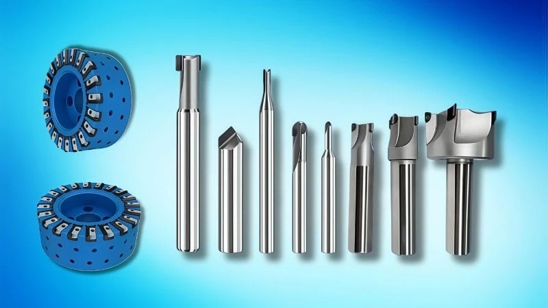
The core difference lies in their physical design and primary application. PCD end mills1 are smaller, versatile tools with cutting edges on the sides and bottom, ideal for slotting, profiling, and deep cavity creation. In contrast, PCD face mills2 are larger, indexable tools with cutting edges strictly on the periphery of a flat disk, engineered specifically for high-efficiency, broad surface flattening.
Structural and Design Variations
What exactly makes the physical design of a PCD end mill different from a PCD face mill?
The primary structural difference lies in how and where the Polycrystalline Diamond (PCD)3 cutting edges are mounted. An end mill features PCD tips brazed along its cylindrical sides and bottom, designed for multi-directional cutting. Conversely, a face mill uses a wider tool body that holds PCD inserts primarily on its outer face. This design is optimized exclusively for horizontal material removal.
Cutting Edge Placement and Orientation
Where do the cutting edges actually sit on the tool? This placement dictates how the tool moves through metal.
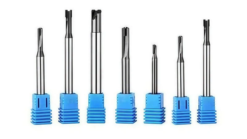
On a PCD end mill, the cutting edges are positioned on both the radial (side) and axial (bottom) surfaces. Manufacturers braze PCD blanks directly onto the twisted or straight flutes of a carbide body. Therefore, the tool can cut sideways and downwards.
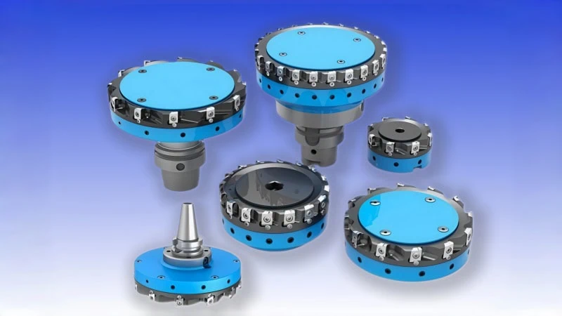
However, a PCD face mill carries its cutting edges on the periphery of a flat disk. The PCD inserts sit at specific angles, usually 45 or 90 degrees. They point downward and slightly outward. The tool body itself does not have flutes carved into its sides.
Think of this like a boring bar versus a broad facing tool on a CNC lathe. The boring bar has edges designed to work inside a tight internal geometry. Meanwhile, the facing tool presents a wide edge to simply clean up a flat exterior face.
Typical Tool Diameter Ranges
Size is a defining structural difference. PCD end mills are physically much smaller than face mills.
End mills must fit into narrow pockets and slots. As a result, standard PCD end mills usually range from 3mm to 25mm in diameter. The solid shank must fit securely inside a standard collet or shrink-fit holder.
In contrast, face mills are built to cover large areas quickly. Their diameters typically start around 50mm. They can easily exceed 250mm for heavy-duty aerospace or automotive engine blocks.
| Tool Type | Typical Diameter Range | Main Mounting Method |
|---|---|---|
| PCD End Mill | 3mm – 25mm | Cylindrical Shank (Collet/Shrink-fit) |
| PCD Face Mill | 50mm – 250mm+ | Arbor Mount |
Available sizes depend heavily on your machine’s spindle limits and tooling manufacturer capabilities, so verify specifications before planning a process.
Monoblock Tools Versus Indexable Systems
How are these tools assembled? The construction method directly impacts tool rigidity.
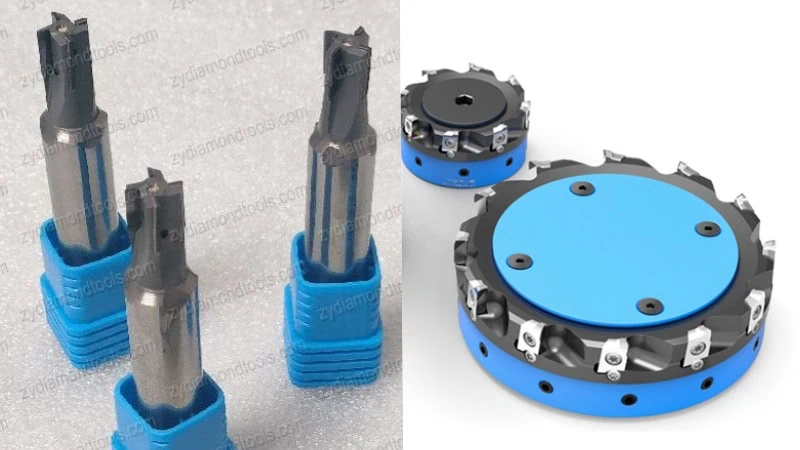
PCD end mills generally use a “monoblock” design. This means the tool is one solid piece. The PCD cutting tips are permanently brazed onto a solid tungsten carbide body. This one-piece design provides the extreme rigidity needed to resist side-loads during radial cutting.
“Monoblock PCD construction minimizes the micro-vibrations that occur with removable parts, ensuring tight tolerances in small pockets.”
On the other hand, PCD face mills almost always use an indexable system4. The main cutter body is a large block of steel or lightweight aluminum. This body features precisely machined pockets. Removable PCD inserts or cartridges are bolted into these pockets.
Why do manufacturers build them this way? Making a 150mm solid carbide tool body would be incredibly heavy and expensive. An indexable steel body with small PCD inserts solves this problem. It keeps the large tool lightweight, balanced, and affordable.
Contrasting Machining Capabilities
What exactly dictates whether a CNC programmer selects a PCD end mill or a face mill for a specific operation?
The selection relies entirely on the required tool path geometry and the target feature. A PCD face mill is engineered strictly for horizontal tool paths to flatten broad, open external surfaces. Conversely, a PCD end mill is a highly versatile cutter designed to move laterally and axially, making it essential for carving internal slots, complex external profiles, and deep, enclosed cavities.
Broad Surface Flattening Operations
How do you efficiently level a massive block of raw aluminum? This process is known as facing. For this task, the PCD face mill is the undisputed champion.
The tool moves horizontally across the top of the workpiece. It removes a shallow layer of material to create a perfectly flat plane. Face mills cannot cut deep into the sides of a part. Instead, they excel at clearing wide, unobstructed areas.
Think of a face mill like a large grinding wheel on a surface grinder5. It primarily interacts with the topmost layer of the material and does not dig narrow channels.
For example, automotive manufacturers rely heavily on PCD face mills. They use them to deck aluminum engine blocks and cylinder heads. The broad cutter easily spans the entire width of the engine block casting in a single, smooth pass.
“When flattening large automotive castings, face mills ensure the entire surface is leveled consistently without relying on complex, overlapping tool paths.”
Typical axial depth of cut (DOC) for a PCD face mill finishing pass might range from 0.1mm to 0.5mm. Optimal cutting depths depend on the specific aluminum alloy and machine rigidity, so consult your tooling data for exact parameters.
Slotting Profiling and Cavity Creation
What happens when you need to machine a deep pocket inside a solid block? A face mill is useless here. It is too wide and lacks the necessary side-cutting geometry. This is exactly where the PCD end mill takes over.
End mills are the multi-tools of the CNC milling world. They easily perform slotting, which means cutting a narrow channel directly into the material. Furthermore, they handle profiling operations effortlessly. Profiling involves tracing the outside boundary of a complex part to shape its final external contour.
Most importantly, end mills are vital for cavity creation. Aerospace parts6, like intricate aluminum valve housings, often feature deep internal pockets. The end mill drops into the material and precisely mills away the inside walls.
Consider the difference between an external turning tool and an internal boring bar on a CNC lathe. The face mill works purely on the vast outside surface. Meanwhile, the end mill is built to reach deep inside the part’s restrictive internal geometry.
Axial Plunging Limitations
Can the cutter move straight down along the Z-axis like a standard drill bit? This specific movement is called plunging. These two tools handle this vertical movement very differently.
PCD face mills generally cannot plunge. The center of a face mill body is usually hollow or completely devoid of cutting edges. If you force a face mill straight down into solid metal, the blunt center of the tool will violently crash into the workpiece. Therefore, face mills must always enter the material from the outside edge.
Conversely, how does a PCD end mill enter solid metal? While some PCD end mills are technically built as “center-cutting” tools, direct straight-down plunging (Z-axis only) is highly discouraged in professional machining. PCD is extremely hard but very brittle. A direct plunge creates extreme crushing force at the dead center of the tool, which can instantly shatter the expensive diamond edge.
To safely enter solid material without a pre-drilled hole, CNC programmers must use a gradual ramping toolpath or helical interpolation. These angled entry methods ease the PCD end mill into the metal. They maintain proper cutting speeds and protect the fragile diamond tips.
| Tool Type | Direct Z-Axis Plunging | Safe Entry Method |
|---|---|---|
| PCD End Mill | Highly Discouraged (High risk of chipping) | Ramping or Helical Interpolation |
| PCD Face Mill | No | Enter horizontally from outside edge |
Understanding these specific entry limitations prevents catastrophic tool crashes. It also dictates exactly how your CAM software must program the initial approach.
Efficiency and Output Quality Comparison
When evaluating a machining process, how do these two cutters actually compare in terms of speed and final part quality?
PCD face mills deliver vastly superior material removal rates and smoother surface finishes across large, flat areas due to their wide diameter and multiple cutting edges. Conversely, PCD end mills remove less material per pass and are more susceptible to tool deflection, but they maintain the essential precision required for intricate, localized part details.
Differences in Material Removal Rates
Material Removal Rate (MRR)7 dictates how fast a tool clears metal. Face mills take a massive bite out of cycle times. A 100mm PCD face mill can clear a wide aluminum plate in a single pass.
Meanwhile, a 12mm PCD end mill requires dozens of overlapping passes to clear that same area. Therefore, the face mill offers a significantly higher MRR for broad flat surfaces because the larger tool simply covers more ground per minute.
Surface Finish Variations Across Large Areas
Surface finish is a critical quality metric in precision manufacturing. When machining broad surfaces, the PCD face mill easily wins. It often utilizes specialized “wiper” inserts. These flat edges physically smooth out the metal as they spin.
Consequently, a face mill can achieve mirror-like finishes. It often reaches a roughness average (Ra)8 of 0.4 microns or better on aluminum parts.
In contrast, using a PCD end mill for large flat areas creates surface problems. The tool must step over and make multiple adjacent cuts. This process inevitably leaves visible witness marks, or slight ridges, where the tool paths overlap. If you need a perfectly smooth, uniform plane, the wide cutter is absolutely mandatory.
Susceptibility to Tool Deflection
Tool deflection refers to the physical bending of the cutter during operation. This bending ruins dimensional accuracy. PCD end mills are highly susceptible to this specific problem.
They experience heavy radial cutting forces pushing against the side of the tool. If the end mill is long and thin, it will bend slightly away from the metal. This is similar to a long boring bar vibrating and deflecting inside a deep lathe chuck. To minimize this, machinists must use shorter tools or significantly reduce feed rates.
Conversely, PCD face mills experience very little deflection. The cutting forces are primarily axial. They push straight up into the massive, rigid machine spindle. This vertical force distribution guarantees excellent stability, even under heavy cutting loads.
| Metric | PCD Face Mill | PCD End Mill |
|---|---|---|
| Material Removal Rate (Broad Areas) | Very High | Low |
| Surface Finish (Large Flats) | Excellent (Ra 0.4 achievable) | Poor (Visible overlapping marks) |
| Primary Cutting Forces | Axial (Pushes into spindle) | Radial (Pushes sideways) |
| Deflection Risk | Very Low | High (Depends on tool length) |
Maintenance and Cost Differences
When planning the long-term tooling budget for your CNC shop, how do the maintenance requirements and overall costs of these two cutters actually compare?
The primary difference lies in tool management logistics. PCD end mills require specialized factory re-sharpening when the cutting edges wear out. In contrast, PCD face mills simply require a quick swap of their indexable diamond inserts. Consequently, face mills provide a lower long-term cost per part9, while solid end mills have a lower initial price but higher maintenance expenses.
Sharpening Solid Cutters vs Replacing Inserts
How do you keep these superhard tools cutting efficiently over time? Maintenance procedures for these two cutters happen in entirely different locations.
When a solid PCD end mill becomes dull, you cannot fix it on the shop floor. The tool must be removed from the CNC machine and shipped to a specialized re-sharpening facility. There, technicians use advanced Electrical Discharge Machining (EDM)10 or laser grinding equipment to precisely restore the diamond edge. This process takes time. You must keep backup end mills in your inventory to prevent machine downtime while dull tools are out for repair.
Think of this like maintaining a solid carbide drill bit. Once it gets dull, it must leave the machine entirely for professional regrinding.
On the other hand, a PCD face mill stays right in the machine spindle. It uses an indexable system. When an insert wears out, the CNC operator simply uses a Torx wrench to rotate or replace the dull insert. This takes only a few minutes. The large cutter body never leaves the factory floor. This is exactly like swapping a carbide insert on a standard turning toolholder on your lathe.
Cost Per Part in High-Volume Production
Which tool is actually cheaper to run in the long term? The answer depends entirely on your production volume.
A solid PCD end mill usually has a lower initial purchase price. However, you pay a heavy penalty in maintenance. Every time it gets sharpened, the tool diameter shrinks slightly. Eventually, the tool becomes too small for your tolerance limits and must be completely thrown away.
Conversely, a large custom PCD face mill requires a massive initial investment. The heavy steel or aluminum cutter body is expensive. However, in high-volume production, it quickly pays for itself. You only buy the expensive tool body once. After that, you are only buying the small, relatively inexpensive diamond inserts.
“For continuous automotive production lines, the ability to swap cheap inserts drastically drives down the final cost per machined casting.”
Let us look at a practical cost comparison for machining high-silicon aluminum transmission housings:
| Cost Factor | PCD Face Mill (Indexable) | PCD End Mill (Solid) |
|---|---|---|
| Initial Purchase Price | High (Expensive body + inserts) | Low to Medium |
| Maintenance Method | In-machine insert swap | Factory re-sharpening |
| Maintenance Downtime | 2 to 5 minutes | 1 to 2 weeks (Shipping time) |
| Long-Term Cost Per Part | Very Low | Moderate to High |
Exact tool life, re-sharpening fees, and replacement insert costs vary depending on the abrasive nature of your material and local vendor pricing. Always calculate the expected cost-per-part data for your specific production run.
Conclusion
Understanding the distinct differences between a PCD end mill and a face mill is crucial for optimizing your manufacturing workflow. Face mills are your best option for rapidly leveling large surface areas with a superior finish. End mills remain essential for precision contouring, slotting, and plunging into tight spaces. By analyzing your specific part geometry and production volume, you can select the right tooling combination to maximize efficiency and minimize long-term costs. If you need expert guidance on selecting the perfect superhard tooling for your next CNC project, please feel free to contact us!
References
- PCD End Mills1 – ZYDiamondTools blog detailing the definition, types, and primary applications of PCD end mills in CNC machining.
- PCD face mills2 – ZYDiamondTools product page featuring high-performance indexable PCD face mills for aluminum machining.
- Polycrystalline Diamond (PCD)3 – ScienceDirect topic page covering the material properties, manufacturing processes, and industrial uses of Polycrystalline Diamond.
- Indexable System4 – ZYDiamondTools article explaining how indexable systems maximize economics and flexibility with PCD and CBN inserts.
- Surface Grinder5 – Wikipedia article providing fundamental information on the mechanical operation of a surface grinder.
- Aerospace Parts Machining6 – ZYDiamondTools guide on the specific applications and necessity of PCD cutters in the aerospace sector.
- Material Removal Rate (MRR)7 – Wikipedia article detailing the mathematical definition and industrial importance of Material Removal Rate.
- Roughness Average (Ra)8 – Wikipedia resource explaining the physics, measurement methods, and standards for surface roughness.
- Long-Term Cost Per Part (TCO)9 – ZYDiamondTools breakdown of Total Cost of Ownership logic for evaluating superhard tooling investments.
- Electrical Discharge Machining (EDM)10 – ZYDiamondTools article discussing how EDM technology is utilized to shape and sharpen PCD tools.


