-
Whatsapp: +86 13526572721
-
Email: info@zydiamondtools.com
-
Address: AUX Industrial Park, Zhengzhou City, Henan Province, China
-
Whatsapp: +86 13526572721
-
Email: info@zydiamondtools.com
-
Address: AUX Industrial Park, Zhengzhou City, Henan Province, China

Maximizing Aerospace Drilling Performance: A Technical Guide to PCD Drills

When it comes to drilling precise holes in advanced aerospace materials, how can you truly maximize performance and ensure every component meets the highest standards using Polycrystalline Diamond (PCD) drills?
Maximizing aerospace drilling performance with PCD tools requires a comprehensive understanding of their intrinsic material properties, optimal drill design engineering for specific applications, precise control over machining parameters and setup, and effective strategies for addressing common challenges to ensure tool longevity and part integrity. By mastering these interconnected areas, manufacturers can fully leverage the benefits of PCD technology.
This technical guide provides an in-depth exploration of PCD drills, covering everything from their fundamental material science and design considerations to advanced application techniques and best practices for maintenance, ultimately enabling users to achieve superior drilling outcomes in demanding aerospace environments.
What Intrinsic Material Properties Make PCD Superior for Demanding Aerospace Applications?
So, what exactly makes Polycrystalline Diamond (PCD) so special for those really tough cutting jobs in the aerospace world?
PCD’s superiority for demanding aerospace applications stems directly from its unique material properties, primarily its exceptional hardness, excellent wear resistance, and good thermal conductivity. These characteristics allow PCD tools to effectively machine challenging aerospace materials like composites and high-strength alloys, leading to longer tool life and better surface finishes compared to many conventional cutting tool materials.
Essentially, PCD combines the incredible hardness of natural diamond with a structure that gives it enough toughness for industrial cutting. This makes it a powerful and reliable choice for precision work in the aerospace industry, especially when dealing with materials that are very difficult to machine with other tools.
Deep Dive into PCD Synthesis and Microstructure for Cutting Tools
Polycrystalline Diamond, or PCD, isn’t just a single piece of diamond like you might see in jewelry. Instead, it’s a cleverly engineered material perfect for cutting tools.
Think of it like making a super-strong, high-tech cookie. Scientists take tiny diamond powders, which are like the super-hard chocolate chips, and mix them with a metallic binder, often cobalt, which acts like the cookie dough holding everything together. This mixture is then put under extremely high pressure and high temperature – a process called HPHT sintering. It’s like baking that cookie in a super-hot, super-squeezy oven!
The result is a solid PCD layer where countless tiny diamond crystals are fused together and also bonded with the metallic binder. These diamond crystals are not all lined up in the same direction; they are randomly oriented. Why is this important? This random jumble of super-hard crystals means the PCD is consistently hard in all directions, which is great for a cutting tool that needs to withstand forces from various angles. The strong bonds between the diamond grains themselves, and between the diamond and the binder, create a very dense and robust structure. These PCD key properties1 are the foundation for PCD’s amazing cutting abilities, giving it the strength and resilience needed for tough aerospace jobs.
The Impact of Diamond Grain Size and Binder on Wear Resistance and Toughness
Now that we know how PCD is made, let’s see how tiny changes in its “recipe” can make a big difference in how it performs. The two main ingredients we can tweak are the size of the diamond grains and the amount or type of metallic binder used. These factors directly influence how well the PCD tool resists wearing down (wear resistance) and how well it can resist chipping or breaking (toughness).
- Diamond Grain Size: Little Grains, Big Impact
The size of the individual diamond crystals in the PCD structure matters a lot.- Fine Grains: Using smaller diamond grains (sometimes even less than a micron, which is super tiny!) generally makes the PCD more resistant to wear. This is because there are more cutting edges packed closely together, leading to a smoother cutting action. Think of it like using very fine sandpaper – it’s great for creating a smooth finish and lasts longer on abrasive materials. Fine-grain PCD is often preferred for machining highly abrasive aerospace materials like Carbon Fiber Reinforced Polymers (CFRP) or for achieving very fine surface finishes.
- Coarse Grains: Using larger diamond grains can make the PCD tougher and more resistant to fractures or chipping. This is useful for “roughing” operations where a lot of material needs to be removed quickly, or when the cutting action might be interrupted (like hitting a gap). Imagine using a saw with bigger, stronger teeth for heavy-duty cutting.
The choice of diamond grain size, which can range from sub-micron to around 25-50 microns or even larger, really depends on the specific aerospace material being cut and the type of machining operation. It’s worth noting that the specific grain sizes offered and their recommended applications can vary between PCD suppliers, so it’s always a good idea to consult their technical data for your particular needs.
- The Role of the Binder: Holding it All Together
The metallic binder, usually cobalt, plays a crucial role. It acts like the glue holding the diamond grains together and also contributes significantly to the overall toughness of the PCD.- Binder Content: The amount of binder used is a balancing act. Increasing the amount of binder can make the PCD tougher and more resistant to impact. However, it might slightly reduce the overall hardness and wear resistance because there’s less diamond material at the cutting edge. Conversely, less binder means a harder PCD with potentially higher wear resistance, but it might also be more brittle.
It’s a bit like the recipe for a cake – the right amount of each ingredient is needed for the best result. Tool manufacturers carefully select the binder content to optimize PCD for specific applications.
- Binder Content: The amount of binder used is a balancing act. Increasing the amount of binder can make the PCD tougher and more resistant to impact. However, it might slightly reduce the overall hardness and wear resistance because there’s less diamond material at the cutting edge. Conversely, less binder means a harder PCD with potentially higher wear resistance, but it might also be more brittle.
Ultimately, there’s often a trade-off between wear resistance and toughness. A PCD grade designed for extreme wear resistance might be less tough, while a tougher grade might not wear as slowly. Engineers select the PCD grade that offers the best balance for the specific aerospace component and machining process.
Comparative Technical Breakdown: PCD vs. Advanced Carbide Grades in Aerospace Contexts
When it comes to cutting tools for aerospace, PCD isn’t the only option, but it often stands out, especially when compared to advanced cemented carbide tools2 (often just called carbide). Let’s see how they stack up in key areas important for aerospace manufacturing.
| Feature | Polycrystalline Diamond (PCD) | Advanced Carbide Tools | Significance in Aerospace |
|---|---|---|---|
| Hardness | Exceptionally high (often 5000-8000 on Knoop scale or higher) | High (typically 1500-2500 on Knoop scale) | PCD is vastly harder, leading to superior abrasion resistance on hard or abrasive materials. |
| Wear Resistance | Outstanding, especially with abrasive materials. | Good to very good, but wears faster than PCD in many cases. | PCD tools can last many times longer (e.g., 20-100x) when machining CFRP or high-silicon aluminum. |
| Toughness | Moderate to good (varies significantly with PCD grade) | Good to excellent (generally tougher than PCD) | Carbide can be more forgiving in unstable setups or heavy interrupted cuts. |
| Thermal Conductivity | Very high | Moderate | PCD efficiently pulls heat away from the cutting edge, protecting tool and workpiece. |
| Chemical Stability | Highly stable with non-ferrous materials like aluminum, composites, titanium (at appropriate temps). Reactive with iron/steel at high cutting temps. | Generally more versatile across a wider range of metals. | PCD excels in non-ferrous aerospace alloys and composites, which are very common. |
Why PCD often wins in Aerospace:
- Machining Abrasive Composites: Aerospace structures increasingly use Carbon Fiber Reinforced Polymers (CFRPs) and Glass Fiber Reinforced Polymers (GFRPs). These materials are incredibly abrasive and quickly wear down carbide tools. PCD, with its extreme hardness, can machine these materials for much longer, maintaining accuracy and surface finish. For instance, when drilling thousands of rivet holes in a CFRP aircraft fuselage panel, PCD drills can maintain consistent hole quality for a far greater number of holes than carbide drills.
- High-Silicon Aluminum Alloys: Aerospace components also use aluminum alloys containing silicon, which is very abrasive. PCD tools dramatically outperform carbide in these applications, leading to significant increases in tool life and productivity. Industry observations suggest tool life improvements of 25 to over 100 times that of uncoated carbide are achievable.
- Longer Tool Life = More Uptime: Because PCD tools last so much longer, machines don’t need to be stopped as often for tool changes. This means more production time and less manufacturing cost per part, which is critical in the demanding aerospace sector.
However, it’s important to note that advanced carbide tools are still very useful. They are generally less expensive upfront and can be more suitable for materials like aerospace-grade steels or titanium alloys if the specific PCD grade isn’t optimized for titanium’s unique challenges (though specialized PCD grades for titanium do exist). The choice always depends on the specific material, the operation, and the economic goals.
Thermal Conductivity and Stability of PCD at Aerospace Machining Temperatures
Heat is a big enemy in machining. When a tool cuts material, especially at high speeds common in aerospace manufacturing, a lot of friction is generated, and this means heat! How a cutting tool material handles this heat is crucial for its performance and lifespan.
- PCD: A Great Heat Manager
Diamond is an excellent conductor of heat. This means PCD, which is mostly diamond, is very good at drawing heat away from the tiny area where the cutting actually happens – the cutting edge. Think of it like a heat sink on a computer processor; it pulls damaging heat away from the critical part. This high thermal conductivity offers several benefits:- Keeps the Edge Cooler: By moving heat away, the cutting edge stays cooler. This helps the PCD maintain its hardness and sharpness for longer.
- Protects the Workpiece: In aerospace, many materials, especially composites, are sensitive to heat. If too much heat builds up, it can damage the material being cut (e.g., cause delamination or resin degradation in CFRP). PCD’s ability to manage heat helps prevent this.
- Reduces Wear: A cooler cutting edge generally wears down more slowly.
- Staying Stable When Things Get Hot (Thermal Stability)
Thermal stability refers to how well a material keeps its important properties (like hardness) when it gets hot. Diamond itself is very stable at high temperatures. However, in PCD, the metallic binder (often cobalt) can be the limiting factor.
If PCD gets too hot, typically around 600°C to 700°C (that’s about 1112°F to 1292°F) when cutting in air, a few things can happen:- The binder material can soften, weakening the PCD structure.
- The diamond itself can start to transform into graphite (the soft stuff in pencils) if oxygen is present, losing its super-hardness. This process is called graphitization.
Therefore, while PCD is great at conducting heat away, there’s still a maximum temperature it can handle effectively. It’s important to remember that this temperature limit can vary based on the specific PCD grade, the amount and type of binder, and the cutting environment. Always check the PCD tool supplier’s specifications for recommended operating temperature ranges and conditions.
In aerospace machining, especially when cutting materials like titanium alloys or at very high speeds in composites, managing the temperature at the cutting edge is vital. This is often done by using coolants, even though PCD itself has good thermal conductivity. The coolant helps to remove heat from the overall cutting zone, keeping the PCD tool within its optimal operating temperature range and prolonging its life. This careful heat management is key to leveraging PCD’s strengths in demanding aerospace applications.

How Do You Engineer the Optimal PCD Drill Design for Specific Aerospace Materials and Operations?
So, when you need the perfect PCD drill for an aerospace job, how do you make sure its design is spot on for the tricky materials and precise holes you’re dealing with?
Engineering the optimal PCD drill design for specific aerospace materials and operations involves carefully considering several key elements: the drill point geometry, flute design, the specific PCD grade and vein thickness, and the coolant delivery strategy. Each of these factors must be tailored to the material being drilled—whether it’s a tough composite or a high-strength alloy—and the desired outcome, such as hole quality and tool life.
By customizing these design aspects, engineers can create PCD drills that not only cut efficiently but also minimize damage to sensitive aerospace components, ensure dimensional accuracy, and maximize the tool’s operational lifespan. This directly impacts manufacturing quality and cost-effectiveness in the high-stakes aerospace industry.
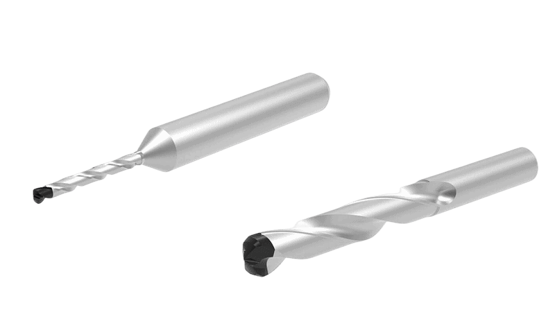
Advanced Drill Point Geometries (e.g., specialized angles, multi-facet, sandwich drills) for Composites vs. High-Strength Alloys
The “business end” of the drill, its point, is where the magic happens. Its shape, or geometry, is super important and needs to be different for different aerospace materials. Why? Because drilling into a lightweight composite is very different from drilling into a super-strong metal alloy.
- Drilling Composites (like Carbon Fiber Reinforced Polymers – CFRP):
These materials are made of strong fibers embedded in a resin. The goal is to cut these fibers cleanly without pulling them out (fiber pull-out) or causing layers to separate (delamination3). PCD drills for drilling composites4 are specialized for these tasks.- Special Point Angles: Instead of very sharp, pointy tips like on a wood drill, PCD drills for composites often have flatter point angles, perhaps around 90 to 120 degrees. Sometimes, specialized “brad point” or “dagger point” designs are used. These help reduce the pushing force (axial thrust) as the drill enters the material, which is a big help in preventing delamination. For applications requiring flush fasteners, specialized tools such as PCD countersink drills for composites5 are also engineered to create precise chamfers while maintaining hole integrity.
- Multi-Facet Grinds: Imagine the drill point having many small cutting faces (facets) instead of just two. Drills with 8, 10, or even more facets are common for composites. These multiple facets distribute the cutting load more evenly, lead to a smoother cutting action, and improve the quality of the hole, especially at the entry and exit.
- “Sandwich” or Double-Angle Drills: When drilling stacks of different materials, like CFRP on top of aluminum (a common aerospace sandwich), special drill point designs known as “sandwich drills” or “double-angle points” are often used. These might have one angle optimized for the composite and another for the metal, helping to create a clean hole through both layers.
- Drilling High-Strength Alloys (like Titanium or Inconel):
These metals are incredibly tough and generate a lot of heat when drilled.- Robust Point Angles: For these tough metals, PCD drills often use stronger, more robust point angles, typically in the range of 130 to 140 degrees.
- Self-Centering Geometries: To prevent the drill from “walking” or skittering across the hard metal surface when starting a hole, geometries like “split points” are used. These help the drill start cutting exactly where it’s supposed to.
- Edge Preparation: The super-hard PCD cutting edge can sometimes be a bit brittle. For tough metals, a tiny chamfer or hone (a slight rounding) might be applied to the cutting edge. This makes the edge stronger and helps prevent it from chipping under high cutting forces.
It’s important to remember that the ideal drill point angles, the number of facets, and other geometric features can significantly impact performance. Optimal designs often vary based on the specific type of composite or alloy, as well as individual supplier recommendations, so consulting their technical guides is crucial for making the best choice.
Flute Design Optimization for Efficient Chip Evacuation in Challenging Aerospace Materials
Once the drill point cuts the material, the leftover bits, called chips (or dust, in the case of composites), need to get out of the hole quickly and smoothly. That’s the job of the spiral grooves on the drill body, known as flutes. If chips don’t get out efficiently, they can clog the hole, damage the surface finish, or even cause the drill to break.
- Why Chip Evacuation is Extra Important in Aerospace:
- Abrasive Composite Dust: When drilling CFRP, the “chips” are actually fine, abrasive dust. This dust needs to be pulled out efficiently to prevent it from excessively wearing the drill or damaging the hole.
- Sticky Metal Chips: Some aerospace aluminum alloys can produce gummy, sticky chips. Titanium chips can also be long and stringy. If these aren’t cleared well, they can wrap around the drill or get stuck in the flutes.
- Deep Holes: Aerospace parts often require deep holes. The deeper the hole, the harder it is for chips to escape, making flute design even more critical.
- Key Flute Design Features:
- Flute Shape and Size: Flutes can have different shapes. For example, “parabolic” flutes have a more open design that helps chips flow out more easily, especially in deeper holes. Wider, more open flutes are generally better for chip removal.
- Helix Angle: This is the angle of the spiral flute.
- A low helix angle (think of a gentler spiral, maybe 15-25 degrees) is often better for hard, brittle materials that produce small, broken chips.
- A high helix angle (a steeper spiral, maybe 30-45 degrees) is typically used for softer, more ductile materials that produce longer, continuous chips. The steeper angle helps to actively “pull” these chips out of the hole. Aerospace applications might use a range depending on the material.
- Polished Flutes: Making the surface of the flutes very smooth and polished helps a lot. This reduces friction, so chips (and especially abrasive composite dust) can slide out more easily instead of sticking. This is a common feature on high-performance PCD drills.
Optimizing the flute design ensures that chips are cleared away efficiently, leading to better hole quality, longer tool life, and more reliable drilling in even the most challenging aerospace materials.
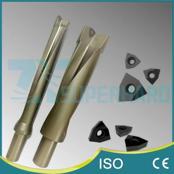
Selecting PCD Grade and Vein Thickness for Application-Specific Rigidity and Wear Characteristics
We’ve talked about the drill’s shape, but the actual PCD material at the cutting edge also needs to be chosen carefully. As we learned earlier, PCD isn’t all the same; it comes in different “grades” based on things like diamond grain size and binder content. The thickness of this PCD layer (often called the “vein”) also matters.
- Choosing the Right PCD Grade:
The “grade” of PCD refers to characteristics like the average size of the diamond particles and the amount of metallic binder.- Finer Diamond Grains (e.g., 2µm to 10µm): These grades usually offer the best wear resistance and can produce the sharpest cutting edges. This makes them ideal for drilling highly abrasive materials like CFRP, where they can last a long time and create very clean holes. They are also good for achieving excellent surface finishes in aluminum alloys.
- Medium Diamond Grains (e.g., 10µm to 25µm): These grades offer a good balance between wear resistance and toughness. They are often used for general-purpose drilling in aerospace aluminum alloys and some other non-ferrous metals.
- Coarser Diamond Grains (e.g., 25µm and larger, or mixed-modal grades with a mix of sizes): These grades are generally the toughest. They are better at handling interrupted cuts (where the drill repeatedly enters and exits the material) or when drilling tougher aerospace alloys where chipping of the cutting edge is a concern. However, they might not produce as fine a surface finish as finer grades.
- PCD Vein Thickness:
The PCD cutting edge isn’t solid PCD all the way through the drill tip. Usually, a layer of PCD (the “vein”) is sintered onto a tougher cemented carbide substrate, which forms the body of the drill tip. The thickness of this PCD layer is an important design choice.- Thicker Veins (e.g., 0.5 mm to 1.0 mm, sometimes more):
- More Regrinds: A thicker layer of PCD means there’s more material available to be sharpened. This allows the drill to be reground or reconditioned multiple times, potentially extending its overall useful life significantly. This is a big plus in aerospace where tools are expected to last.
- Increased Edge Strength: For some heavy-duty applications, a thicker vein can provide more support behind the cutting edge, making it more robust.
- Thinner Veins:
- While less common for aerospace drills designed for longevity and multiple regrinds, thinner PCD layers might be found on some specialized or smaller-diameter tools.
- Thicker Veins (e.g., 0.5 mm to 1.0 mm, sometimes more):
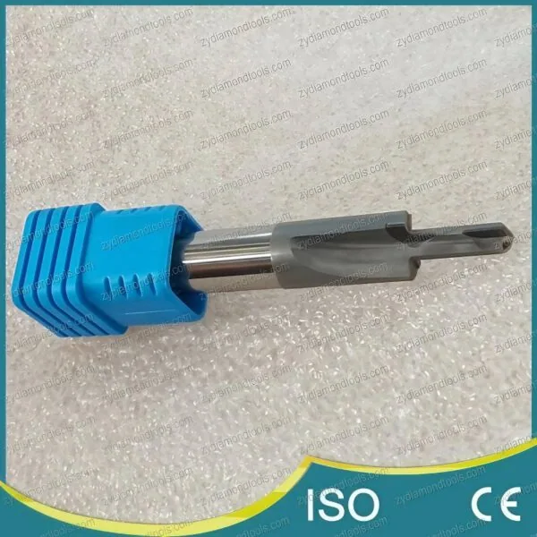
Through-Tool Coolant Strategies: Design Considerations and Benefits for PCD Drills
Keeping things cool is essential when drilling, especially with high-performance PCD tools in demanding aerospace materials. Even though PCD is good at handling some heat, effective cooling can dramatically improve tool life and hole quality. One of the best ways to deliver coolant precisely where it’s needed is through the drill itself, such as with a PCD drill tool with internal cooling6.
- Why Internal Coolant is a Big Deal for Aerospace PCD Drills:
- Targeted Cooling: Internal coolant channels deliver fluid (like water-based emulsions or specialized cutting fluids) directly to the cutting edges and the point of drilling. This is much more effective than just flooding the outside of the drill with coolant.
- Heat Removal: It efficiently flushes away heat generated by friction, keeping the PCD cutting edges cooler. This helps prevent the PCD from overheating, which maintains its hardness and slows down wear.
- Chip Evacuation: The pressurized coolant flow also helps to forcefully flush chips and abrasive dust out of the hole and away from the cutting zone. This is super important in deep holes or when drilling materials that produce difficult-to-manage chips (like sticky aluminum or powdery composites).
- Lubrication: The coolant can also provide lubrication, reducing friction between the drill and the workpiece.
- Designing Coolant Channels in PCD Drills:
Engineers think carefully about how to design these internal coolant paths:- Number of Coolant Holes: PCD drills for aerospace might have one, two, or sometimes three or more internal coolant holes. More holes can provide better coolant distribution.
- Exit Point Design: The location where the coolant exits the drill is critical. Sometimes the holes exit directly at the cutting tip, aiming coolant right at the cutting action. Other designs might have coolant exiting along the flutes to help push chips up and out.
- Hole Diameter and Shape: The size of the coolant holes needs to be large enough to allow good coolant flow and pressure, but not so large that they weaken the drill body, especially in smaller diameter drills.
- Smooth Internal Passages: The internal channels are designed to be smooth to ensure an uninterrupted and efficient flow of coolant.
- The Payoff: Benefits of Through-Tool Coolant:
- Significantly Longer Tool Life: By keeping the PCD cooler and flushing away abrasive particles, tool life can be greatly extended.
- Improved Hole Quality: Better cooling and chip removal mean less chance of thermal damage to the workpiece material (like charring in composites) and a smoother, more accurate hole.
- Higher Productivity: With effective cooling, it’s often possible to use higher cutting speeds and feed rates, meaning more holes can be drilled in less time.
- Reliability in Tough Jobs: Essential for deep hole drilling in materials like titanium, or when drilling through stacks of different aerospace materials where heat can get trapped between layers.
Using PCD drills with well-designed through-tool coolant systems is a key strategy for achieving top performance, quality, and efficiency in modern aerospace manufacturing.
What Are the Critical Machining Parameters and Setup Considerations for PCD Drills in Aerospace?
So, you’ve got your advanced PCD drill perfectly designed; how do you actually set up the machine and choose the right settings to get those perfect holes in aerospace parts?
Achieving optimal results with PCD drills in aerospace hinges on critical machining parameters and setup considerations. This primarily involves the precise optimization of cutting speeds, feed rates, and pecking cycles, alongside ensuring high-rigidity tool holding and stable machine tool dynamics. Furthermore, specific strategies for drilling complex stack materials and leveraging real-time process monitoring are essential for success.
These elements work together to prevent defects like delamination or burrs, maximize tool life, and ensure the consistent production of high-quality holes demanded by the aerospace industry. Careful attention to setup and operational details is therefore just as important as the drill design itself for getting the best performance from your PCD tools.
Precision Parameter Optimization: Speeds, Feeds, and Pecking Cycles for Defect-Free Holes (Delamination, Exit Burrs)
Getting the machine settings just right is like tuning a musical instrument – everything needs to be in harmony for a beautiful result. For PCD drills, the main “notes” to tune are cutting speeds, feed rates, and special drilling actions called pecking cycles. Getting these wrong can lead to ugly problems like delamination (layers separating in composites) or burrs (rough edges on metal).
- Cutting Speed (Vc): How Fast the Drill Spins
Cutting speed refers to how fast the outer edge of the drill is moving as it cuts into the material. It’s usually measured in meters per minute (m/min) or surface feet per minute (SFM).- PCD Advantage: PCD tools can often run at much higher cutting speeds than traditional carbide tools, especially when drilling aerospace materials like aluminum alloys and composites. This means you can make holes faster!
- Material Matters:
- For CFRP (Carbon Fiber Reinforced Polymer), higher speeds (e.g., 100 to 300 m/min, or about 330 to 980 SFM) are often possible with PCD. But, going too fast can generate too much heat and damage the resin in the composite.
- For aluminum alloys, PCD really shines at high speeds, sometimes exceeding 500 m/min (over 1600 SFM).
- For titanium alloys, which are very tough and don’t conduct heat well, more moderate cutting speeds are usually needed, even with PCD – perhaps in the range of 30 to 60 m/min (about 100 to 200 SFM).
- A Key Reminder: “These cutting speed ranges are general guidelines. The optimal speed for your specific PCD drill, aerospace material, coolant setup, and machine tool can vary significantly. Always start with the recommendations from your tool supplier and then carefully conduct tests to fine-tune the parameters for your exact situation.“
- Feed Rate (fn or Vf): How Fast the Drill Advances
Feed rate is how quickly the drill moves into the material. It can be measured per spin of the drill (millimeters per revolution, mm/rev, or inches per revolution, IPR) or per minute (millimeters per minute, mm/min, or inches per minute, IPM).- Finding the Balance: If the feed rate is too slow, the drill can rub instead of cut, causing it to wear out faster. If it’s too fast, you can put too much force on the drill, possibly breaking it, or you might get poor hole quality, like delamination in composites or big burrs on metals.
- Precision is Key: Especially in aerospace where holes must be perfect, controlling the feed rate very precisely is crucial.
- Pecking Cycles: The Woodpecker Technique
For deep holes or when drilling tricky materials, a “pecking cycle” is often used. Imagine a woodpecker: the drill goes in a little bit, pulls back out to clear away chips, then goes in a bit deeper, and repeats.- Why Peck?
- Clears Chips: It helps remove chips from deep inside the hole, preventing them from getting packed in.
- Better Cooling: When the drill pulls back, coolant can get to the cutting edges more easily.
- Reduces Heat: It gives the cutting edge a brief moment to cool down.
- Aerospace Uses: Peck drilling is very helpful for deep holes in titanium (to get rid of those stubborn chips) or when drilling composites (to help remove dust and reduce heat buildup). It can also be useful when drilling stacks of different materials.
- Settings for Pecking: You’ll need to set how deep each “peck” is and how far the drill retracts.
- Why Peck?
By carefully choosing and optimizing these speeds, feeds, and pecking strategies, you can drill defect-free holes and get the most out of your PCD tools.
The Importance of High-Rigidity Tool Holding and Machine Tool Dynamics
Imagine trying to write neatly with a wobbly pen – it wouldn’t work very well, right? It’s the same with PCD drills. Because PCD is super hard, it can also be somewhat brittle. Any wobble or vibration can cause the delicate PCD cutting edges to chip or break. That’s why how you hold the drill and the quality of the machine tool are super important.
- Rock-Solid Tool Holding:
The “tool holder” is what clamps the drill into the machine’s spindle. For PCD drills, this holder needs to be extremely rigid and precise.- Why Rigidity is King: A rigid holder grips the drill tightly and ensures it spins perfectly true, without any wobble. This minimizes vibrations that could damage the PCD.
- Good Holder Choices: Special types of holders like hydraulic chucks, shrink-fit holders, or high-precision collet chucks are excellent for PCD. They provide strong, even clamping force and minimize something called “runout7.”
- Runout – The Enemy: Runout means the drill isn’t spinning perfectly centered; it’s wobbling slightly. Even a tiny amount of runout (say, more than 0.005 millimeters or 0.0002 inches at the drill tip) can drastically shorten the life of a PCD drill and lead to poor hole quality. Think of it like a slightly bent axle on a car wheel causing a bumpy ride.
- Machine Tool Dynamics: The Whole Machine Matters
It’s not just the holder; the entire machine tool needs to be up to the task.- Machine Stiffness: The machine itself – its frame, spindle, and moving parts – must be very stiff and well-maintained. An old or less rigid machine can vibrate too much, making it unsuitable for getting the best results with PCD tools.
- Spindle Quality: The spindle is the part of the machine that spins the tool. High-quality bearings in the spindle are essential for smooth, vibration-free rotation, especially at the high speeds often used with PCD drills.
- Vibration Damping: Some machines are better at “damping” or absorbing vibrations. This is a good thing, as it helps protect both the PCD tool and the expensive aerospace part being drilled.
In short, if your setup isn’t rock-solid from the machine spindle all the way to the tip of the PCD drill, you risk vibrations. Vibrations can lead to chipped PCD edges, which means bad holes, shorter tool life, and potentially scrapping very expensive aerospace components. So, a rigid setup is not just nice to have; it’s essential!
Strategies for Hole Entry and Exit in Stack Materials (e.g., CFRP/Al, CFRP/Ti)
Aerospace structures often use “stacks” of different materials bonded together, like a layer of Carbon Fiber Reinforced Polymer (CFRP) on top of a layer of aluminum (CFRP/Al) or titanium (CFRP/Ti). Drilling clean holes through these stacks is a big challenge because each material likes to be drilled differently, and the point where the drill passes from one material to another (the interface) can be especially tricky.
- The Challenges of Stack Drilling:
- Different Personalities: CFRP wants to be sheared cleanly to avoid delamination, while metals like aluminum or titanium can produce burrs (rough edges) or require different cutting forces.
- Interface Issues: As the drill exits one material and enters another, the cutting conditions change abruptly. This can cause problems if not managed.
- Heat and Chips: Heat can get trapped between layers, and chips from one material can damage the next.
- Smart Strategies for Entry and Exit:
- Gentle Entry: When starting the hole, especially if the top layer is a composite like CFRP, it’s often best to use a reduced feed rate. This gentle approach helps prevent splintering, delamination, or cracking at the surface. In some very critical cases, a tiny pilot hole might be drilled first, but often, aerospace manufacturers prefer “one-shot” drilling where the full hole is made in a single operation.
- Crucial Exit Control: Exiting the last layer of the stack cleanly is extremely important.
- Reduce Feed at Exit: Significantly slowing down the feed rate just before the drill breaks through the bottom surface can dramatically reduce exit burrs on metal layers and prevent “push-out” delamination on composite layers.
- Backing Material: Using a “sacrificial” backing plate made of a material like scrap aluminum or even a stiff composite board pressed firmly against the exit surface can provide support. This helps ensure a cleaner exit without damage.
- Drill Design Matters (A Quick Recap): As we discussed earlier, special PCD drill designs like “sandwich drills” or “double-angle point” drills are often engineered specifically for stack materials. These designs, combined with the right parameters, are key to success.
- Navigating Between Layers:
- CFRP/Titanium Stacks: Drilling from CFRP into titanium is particularly tough because titanium generates a lot of heat and produces difficult chips. Pecking cycles might need to be adjusted as the drill transitions from the CFRP (which creates dust) to the titanium (which creates metallic chips). This helps manage the different types of chips and control heat.
- Clamping is Key: Ensuring the layers of the stack are very tightly clamped together is vital. Any tiny gap or vibration between the layers can lead to poor hole quality or even tool damage.
Think of drilling a stack material like navigating a tricky obstacle course. You need the right tool (drill design), the right technique (parameters), and careful attention at each transition point. For example, drilling fastener holes in an aircraft wing, which might have a CFRP skin over an aluminum or titanium internal structure, requires this level of precision to ensure every hole is perfect for the fastener and maintains the structural integrity of the wing.
Real-time Process Monitoring and Adaptive Control Techniques for PCD Drilling
In the world of high-tech aerospace manufacturing, just setting your parameters and hoping for the best isn’t always enough, especially with expensive PCD tools and even more expensive aircraft parts. That’s where “smart” drilling comes in – using sensors to watch the drilling process in real-time and even allowing the machine to adjust itself automatically.
- What is Real-Time Process Monitoring?
Imagine having super-senses for your drilling machine. Process monitoring uses sensors to “listen” and “feel” what’s happening as the PCD drill cuts. These sensors can measure:- Cutting Torque: The twisting force on the drill.
- Thrust Force: The pushing force on the drill.
- Vibrations: Any shaking or wobbling.
- Acoustic Emissions8: The high-frequency sounds made during cutting (like a tiny microphone listening for problems).
This information is collected by a computer, which can then show the machine operator what’s going on, or even use the data to make decisions.
- Why Monitor PCD Drilling?
- Catch Tool Wear Early: As a PCD drill starts to get dull, the cutting forces or torque might gradually increase. Monitoring systems can detect these subtle changes, signaling that it’s time to change the tool before it fails completely or starts making bad holes. This is much better than just drilling a set number of holes and then changing the tool, as it optimizes tool usage.
- Spot Problems Instantly: If there’s a sudden spike in force, it could mean chips are getting clogged, the material has a hard spot, or the drill might have chipped. The system can alert the operator or even stop the machine to prevent major damage.
- Improve Quality and Consistency: By keeping an eye on the process, manufacturers can ensure that every hole is drilled under a consistent set of conditions, leading to higher overall quality.
- Adaptive Control: The Machine That Thinks for Itself
Adaptive control takes process monitoring one step further. It’s like giving the machine tool a brain.- How it Works: The machine uses the real-time sensor data to automatically adjust the drilling parameters – like the feed rate or spindle speed – while it’s drilling.
- An Example: Let’s say the drill enters a slightly harder section of material within an alloy, or it starts to encounter a different material in a stack (like transitioning from CFRP into aluminum). The sensors would detect an increase in torque or force. An adaptive control system could then automatically reduce the feed rate slightly to keep the cutting conditions stable and prevent overloading the PCD drill. Once through the tough spot, it might increase the feed rate again.
- Like Cruise Control: It’s similar to how cruise control in a car automatically gives the engine more or less gas to maintain a steady speed when going uphill or downhill. Adaptive control for drilling tries to maintain optimal cutting conditions.
- Benefits in Aerospace:
Given the extremely high value of aerospace components (you don’t want to scrap a multi-million dollar wing part because of a few bad holes!) and the very strict quality standards, these advanced monitoring and control techniques are incredibly valuable. They help to:- Reduce scrap rates.
- Maximize the life of expensive PCD tools.
- Ensure that every hole meets the required specifications.
- Allow for “lights-out” or minimally supervised machining in some cases.
While these sophisticated systems might not be on every single drilling machine, they represent the cutting edge of technology and are increasingly being adopted in advanced aerospace manufacturing environments to get the absolute best performance and reliability from PCD drilling operations.

How Can You Address Common Challenges and Ensure Tool Longevity in PCD Aerospace Drilling?
Even with the best PCD drills and setups, what common problems can arise in aerospace drilling, and how can you make these advanced tools last as long as possible while ensuring top-quality parts?
Addressing common challenges and ensuring tool longevity in PCD aerospace drilling involves proactively identifying and mitigating wear mechanisms like abrasion and chipping, employing advanced inspection techniques to monitor tool condition, and adhering to best practices for tool reconditioning. Furthermore, careful analysis of surface integrity and mitigation of sub-surface damage in drilled components are crucial for meeting stringent aerospace quality standards.
By understanding how PCD tools wear, how to properly inspect and maintain them, and how to assess the quality of the holes they produce, aerospace manufacturers can maximize the economic benefits of PCD tooling. This approach also helps to consistently produce reliable, high-performance components, which is absolutely vital in the aerospace industry.
Identifying and Mitigating Common Wear Mechanisms (e.g., abrasion, chipping, binder erosion)
Even though PCD (Polycrystalline Diamond) is incredibly hard, PCD drills don’t last forever. Like any tool, they eventually wear out. Understanding how they wear and what to do about it can help you use them for much longer and keep making good parts. Here are some common ways PCD drills wear down:
- Abrasion: The Slow Grind
- What it is: This is like sandpaper slowly rubbing away at the cutting edge of the drill. The sharp edge gradually becomes dull and rounded. Abrasion is very common, especially when drilling materials that have hard or gritty particles, like carbon fiber reinforced polymers (CFRPs) or aluminum alloys with high silicon content (which are common in aerospace).
- How to spot it: The cutting edge will look dull or rounded instead of sharp. You might also notice that the drill needs more force to cut, or the surface finish of the drilled hole isn’t as smooth as it used to be.
- How to fight it:
- Use the right PCD grade. Often, PCD grades with finer diamond grains are better for resisting abrasion in composites.
- Ensure plenty of coolant is flowing right at the cutting edge. This helps wash away the tiny abrasive particles.
- Use the correct cutting speeds and feed rates, as these are key to minimizing many wear problems.
- Chipping: Little Bits Breaking Off
- What it is: This is when small pieces of the PCD material break off the cutting edge. It can be tiny “micro-chipping” that’s hard to see without a microscope, or larger “macro-chipping” that’s more obvious.
- What causes it: Chipping can happen if the cutting forces are too high, if there’s a lot of vibration, if the drill hits a very hard spot unexpectedly, or if the drill is dropped or handled roughly. Using a PCD grade that’s too brittle (not tough enough) for the job can also lead to chipping.
- How to spot it: The cutting edge will look jagged or have noticeable nicks. You might also hear a change in the cutting sound or see a sudden drop in hole quality.
- How to fight it:
- Make sure your machine setup is super rigid to minimize vibrations.
- If chipping is a constant problem, you might need a tougher PCD grade.
- Be careful when drilling into or out of the material, and use pecking cycles if needed.
- Always handle PCD tools with care – they are strong but can be damaged if knocked around.
- Binder Erosion or Leaching: The “Glue” Weakening
- What it is: Remember how PCD has tiny diamond grains held together by a metallic binder (often cobalt)? Sometimes, this binder material can get worn away or even chemically attacked by the cutting fluid or by very high temperatures. When the binder weakens, the diamond grains can fall out, and the tool wears much faster.
- How to spot it: You might see tiny pits or a rougher texture on the PCD surface near the cutting edge. The tool might also seem to get dull very quickly.
- How to fight it:
- Use cutting fluids that are specifically recommended for use with PCD tools and are compatible with the binder material.
- Try to keep cutting temperatures under control by using enough coolant and appropriate cutting parameters.
- Choose PCD grades known for good binder integrity, especially if you’re machining in challenging chemical or thermal environments.
- Thermal Cracking: Trouble from Heat
- What it is: These are small cracks that can appear on the PCD surface, often caused by very rapid changes in temperature (called thermal shock) or just by getting too hot.
- How to spot it: You might see fine cracks on the PCD surface, usually near the cutting edge.
- How to fight it:
- Ensure a consistent and generous flow of coolant to prevent the drill from getting too hot or cooling down too quickly.
- Avoid excessive cutting temperatures by using the right speeds and feeds.
- Pecking cycles can help manage heat, especially in deep holes.
By watching out for these wear types and taking steps to reduce them, you can significantly extend the life of your valuable PCD drills.
Advanced Inspection Techniques for Assessing PCD Drill Wear and Integrity
To know if your PCD drill is still in good shape, if it needs to be sharpened, or if it’s time to replace it, you need to inspect it carefully. Just a quick look isn’t usually enough for these high-performance tools. Here are some advanced ways to check PCD drill wear:
- Visual Inspection with Magnification: The First Check
- What it is: This is the most basic but still very important step. It involves looking closely at the cutting edges of the PCD drill using a good quality toolmaker’s microscope or a high-power magnifying glass (loupe).
- What to look for: You’re looking for the common wear signs we just talked about:
- Is the cutting edge still sharp, or is it rounded (abrasion)?
- Are there any chips or nicks on the edge?
- Can you see any cracks?
- How large is the “wear land” (the flat spot that develops on the flank, or side, of the cutting edge as it wears)?
- Why it’s useful: It’s a quick and easy way to get a general idea of the tool’s condition right on the shop floor.
- Digital Microscopy and Optical Metrology: Getting Precise Measurements
- What it is: These systems use a digital camera connected to a microscope to capture high-resolution images of the drill’s cutting edge. Special software can then be used to take very precise measurements of wear features.
- What it measures: You can accurately measure things like the width of the flank wear land, the size of any chips, or even the radius of a rounded cutting edge.
- Why it’s useful: It gives you exact numbers, not just a visual impression. This data can be recorded and tracked over time to see how quickly a drill is wearing. For example, aerospace companies often set specific limits for flank wear. Once a drill’s wear land reaches that limit (say, 0.2 mm or 0.008 inches), it’s sent for reconditioning. It’s important to note that acceptable wear limits can vary a lot depending on the specific drilling application, the material being drilled, and the required hole tolerances. Companies often establish their own standards based on testing and experience.
- Scanning Electron Microscopy (SEM): The Super-Detailed Look
- What it is: An SEM is a very powerful type of microscope that can magnify things hundreds of thousands of times. It allows scientists and engineers to see extremely fine details of the PCD structure and how it’s wearing.
- Why it’s useful: SEM is usually used for detailed failure analysis or research, perhaps if you’re trying to solve a persistent wear problem or develop better PCD tools. It’s not typically used for routine daily inspections on the shop floor because it’s a specialized lab instrument.
- Non-Contact 3D Scanning: Mapping the Wear
- What it is: These scanners use lasers or structured light to create a complete 3D digital model of the drill’s cutting tip.
- Why it’s useful: This 3D model can be compared to the original design of the drill to see exactly where and how much it has worn. It’s great for tracking wear progression and for ensuring that reconditioned tools match the original specifications.
By using these inspection techniques, especially digital microscopy for regular checks, you can make smart decisions about when to use a drill, when to sharpen it, and when it’s truly worn out. This helps prevent drilling bad holes and saves money in the long run.
Best Practices for PCD Tool Reconditioning: Regrinding and Re-tipping Standards
PCD drills are a significant investment. So, when they get worn, you don’t just throw them away if you can help it! Reconditioning, which usually means carefully sharpening (regrinding)9 the PCD cutting edges, can bring a worn drill back to life, often multiple times. This can save a lot of money compared to buying new drills all the time.
- Regrinding: Giving PCD Drills a New Edge
- What it is: Regrinding involves using very precise CNC (Computer Numerical Control) tool grinding machines equipped with special fine-grit diamond grinding wheels. These machines carefully grind away the worn part of the PCD cutting edge to restore its original sharp geometry.
- The Process:
- Inspection: First, the worn drill is thoroughly inspected to see how badly it’s worn and if it’s suitable for regrinding.
- Cleaning: The drill is cleaned to remove any coolant residue or debris.
- Grinding: The grinding machine very carefully removes the minimum amount of PCD material necessary to create a new, sharp cutting edge. The goal is to perfectly match the drill’s original angles and dimensions.
- Final Inspection: After grinding, the drill is inspected again to make sure it meets all the required specifications for sharpness, geometry, and surface finish.
- How Many Regrinds? The number of times a PCD drill can be reground depends on a few things, like how thick the original PCD layer (vein) was, how much material needs to be removed each time, and the quality of the regrinding process. For critical aerospace applications, it’s essential that regrinding maintains the drill’s exact original specifications.
- Re-tipping: A More Involved Option
- What it is: If a PCD drill tip is very severely damaged, or if the PCD layer has become too thin for further regrinding, re-tipping might be an option. This involves removing the entire old PCD tip segment and brazing (a type of high-temperature soldering) or sintering a brand new PCD tip onto the drill’s carbide body.
- Considerations: Re-tipping is usually more complex and expensive than regrinding. It’s often more common for larger, more complex PCD tools than for smaller drills, but it can be a cost-effective solution for certain types of tools.
- Quality Standards are Key:
- Maintain Original Specs: For aerospace work, it’s absolutely critical that reconditioned PCD drills perform just like new ones. This means the regrinding process must precisely restore the original cutting edge geometry, angles, and tolerances. Any deviation could affect hole quality and part performance.
- Use Specialists: Reconditioning PCD tools is a specialized skill. It’s best to use reputable tool reconditioning services that have the right equipment and proven experience with PCD. Many aerospace companies have very strict procedures for qualifying their reconditioning suppliers.
- Documentation and Traceability: Good reconditioning services will provide documentation showing what was done and confirming that the tool meets specifications. Keeping track of how many times a drill has been reconditioned is also good practice.
Adhering to strict reconditioning standards, which are often defined by the original tool manufacturer or by internal aerospace quality procedures, is paramount. This includes verifying all critical dimensions, edge preparations (like hones or chamfers if they were part of the original design), and the surface finish of the cutting edges after regrinding. By following these best practices, you can maximize the life of your PCD investment and ensure that your reconditioned tools continue to meet the high demands of aerospace drilling.
Surface Integrity Analysis and Sub-surface Damage Mitigation in PCD-Drilled Aerospace Components
When you drill a hole in an aerospace part, the job isn’t done just because the hole looks round and is in the right place. Engineers also care deeply about “surface integrity.” This refers to the condition of the surface of the hole and, just as importantly, the condition of the material just below the surface. Why is this so critical in aerospace? Because aerospace parts are often pushed to their limits, and any tiny flaws or damage caused during drilling can potentially lead to big problems later on, like cracks or even failure of the part.
- What is Surface Integrity?
It includes several things:- Surface Roughness: How smooth or rough the inside wall of the hole is.
- Micro-cracks: Tiny cracks on or just below the surface that you might not see with your naked eye.
- Residual Stresses: Stresses locked into the material around the hole as a result of the drilling process. Some stresses can be good (compressive), but others can be bad (tensile).
- Heat-Affected Zone (HAZ): An area where the material’s properties have been changed by the heat of drilling (especially important in composites).
- Delamination (in composites): Separation of the layers.
- Fiber Pull-out (in composites): Fibers being pulled out instead of cleanly cut.
- Common Issues in PCD Drilling and How to Reduce Them:
Even with advanced PCD drills, these issues can occur if things aren’t optimized.- Delamination and Fiber Pull-out (Mainly in Composites like CFRP):
- How to spot it: Visually (layers separating at hole edge), sometimes with ultrasonic testing (a type of NDT – non-destructive testing), or by cutting the part open and looking under a microscope.
- How to reduce it: Use a very sharp PCD drill with the correct point geometry. Optimize cutting speeds and feed rates (especially lower feed rates at hole exit). Always use a rigid backing material when drilling through composites.
- Thermal Damage / Heat-Affected Zone (Especially in Composites):
- How to spot it: Sometimes you can see discoloration or charring around the hole. Microscopic examination can reveal if the resin in the composite has been degraded by heat.
- How to reduce it: Use a sharp tool (dull tools generate more heat). Ensure effective cooling right at the cutting edge. Use appropriate speeds and feeds to minimize heat generation. PCD’s natural high thermal conductivity helps pull heat away, but bad parameters can still cause problems.
- Micro-cracks (Can occur in both Metals and Composites):
- How to spot it: Special techniques like dye penetrant inspection (a liquid dye seeps into cracks, making them visible) or microscopic examination are needed.
- How to reduce it: Use a sharp drill, avoid using excessive force or tool pressure, and make sure the machining setup is very stable to prevent vibrations.
- Delamination and Fiber Pull-out (Mainly in Composites like CFRP):
- Analyzing Surface Integrity:
Aerospace manufacturers use various methods to check the surface integrity of drilled holes:- Surface Roughness Testers: Instruments that measure the smoothness of the hole wall.
- Microscopy: Looking at the hole surface and cross-sections of the drilled material under a microscope to see details like micro-cracks, fiber damage, or changes in material structure.
- Non-Destructive Testing (NDT): Techniques like ultrasonic inspection are widely used for composites to detect internal delamination or voids around drilled holes without damaging the part.
The ultimate goal is to drill holes that not only meet dimensional requirements but also have excellent surface integrity with minimal or no sub-surface damage. This often involves a continuous improvement loop: drill some test holes, carefully analyze their surface integrity, and if any issues are found, adjust the PCD drill design, the cutting parameters, or the setup until perfect holes are consistently achieved. This attention to detail is what helps ensure the safety and reliability of aircraft and spacecraft.
Conclusion
Successfully implementing PCD drilling solutions in the aerospace industry is a multifaceted endeavor. It requires a deep understanding of the tool material itself, meticulous attention to drill design and engineering, precise control over operational parameters and machine setup, and diligent practices in tool management, inspection, and reconditioning. Furthermore, a commitment to ensuring the highest levels of surface integrity in the drilled components is paramount.
By embracing the technical insights and best practices outlined in this guide, aerospace manufacturers can harness the full potential of PCD drills. This commitment leads to enhanced productivity through longer tool life and faster cycle times, superior component quality with fewer defects, and ultimately, reduced overall manufacturing costs. The journey to mastering PCD drilling is one of continuous learning, careful application, and ongoing optimization, but the rewards in terms of performance, reliability, and the advancement of aerospace technology are substantial.
References
- These PCD key properties1 – ZYDiamondTools blog post detailing the fundamental characteristics of PCD, such as hardness, toughness, and thermal conductivity.
- advanced cemented carbide tools2 – ZYDiamondTools article comparing PCD tools with traditional carbide cutting tools.
- delamination3 – Wikipedia article explaining the phenomenon of delamination, particularly relevant to composite materials.
- drilling composites4 – ZYDiamondTools blog post on PCD solutions tailored for the challenges of machining composite materials.
- PCD countersink drills for composites5 – ZYDiamondTools product page for specialized PCD countersink drills designed for CFRP/GFRP composite materials.
- PCD drill tool with internal cooling6 – ZYDiamondTools product page showcasing a PCD drill specifically designed with internal coolant channels.
- runout7 – Wikipedia article explaining the concept of run-out in mechanical engineering, relevant to tool holding precision.
- Acoustic Emissions8 – Wikipedia article providing information on Acoustic Emission as a phenomenon and its applications in monitoring.
- sharpening (regrinding)9 – ZYDiamondTools guide on the techniques and best practices for sharpening PCD and PCBN cutting tools.


