-
Whatsapp: +86 13526572721
-
Email: info@zydiamondtools.com
-
Address: AUX Industrial Park, Zhengzhou City, Henan Province, China
-
Whatsapp: +86 13526572721
-
Email: info@zydiamondtools.com
-
Address: AUX Industrial Park, Zhengzhou City, Henan Province, China

How to Select and Optimize PCD End Mills for Milling?

So, with all the advanced capabilities of PCD tooling, how do you actually get the most out of a PCD end mill?
Getting the most from a PCD end mill requires a three-step approach: first, identifying the correct high-abrasion, non-ferrous applications where they excel; second, selecting the right tool features like geometry and PCD grade for the task; and third, implementing optimal milling strategies such as high-speed toolpaths and climb milling to protect the tool and maximize performance.
Which Milling Applications Demand a PCD End Mill?
So, when does it actually make sense to use a PCD end mill instead of a standard carbide one?
PCD (Polycrystalline Diamond) end mills are demanded for specific milling operations on highly abrasive, non-ferrous materials where conventional tools fail. They are essential for high-speed face milling and profiling of aluminum alloys, routing and trimming of composites without delamination, and milling fine-detailed graphite electrodes.
Using the right tool for a specific milling operation is critical for success. While a standard carbide end mill1 might handle these materials for a short time, its performance quickly degrades. Let’s explore the specific milling scenarios where PCD end mills are not just better, but truly necessary.
High-Speed Finishing and Mirror Milling of Aluminum Alloys
When performing milling operations on aluminum, especially high-silicon aluminum2 common in the automotive industry, two things happen: the abrasive silicon content wears the tool, and the soft aluminum tends to stick to the cutting edges. This is known as built-up edge (BUE)3, a problem that is especially damaging in milling as it clogs flutes, ruins the surface finish, and can break the tool.
PCD end mills solve this problem completely for milling operations.
- No Chip Clogging: Diamond has very low friction and isn’t chemically reactive with aluminum. This means chips slide effortlessly off the helical flutes of the end mill, preventing BUE even at extreme rotational speeds. This clean cutting action is what enables “mirror milling,” where the milled surface is so smooth (Ra < 0.1 µm) that it looks polished.
- Extreme Milling Speeds: Because there’s no risk of BUE, you can push the spindle speeds and table feeds much higher. A PCD end mill can perform face milling or profile milling operations 5 to 10 times faster than a carbide tool. For a factory producing thousands of aluminum engine blocks or custom wheels, this increase in milling speed translates directly to more parts per hour and lower costs.
Industry Example: In the manufacturing of automotive aluminum alloy wheels, multi-flute PCD end mills are used for the final profile milling pass. A single PCD tool can machine thousands of wheels while maintaining a consistent, bright finish, whereas a carbide tool would need frequent replacement, with finish quality degrading rapidly.
Routing and Trimming Abrasive Composites without Fraying
Composite materials like Carbon Fiber Reinforced Plastic (CFRP) and Glass Fiber Reinforced Plastic (GFRP) are transforming industries like aerospace4 but are notoriously difficult to mill. The abrasive fibers act like tiny files, destroying the sharp cutting edge of a carbide end mill in minutes.
A dull cutting edge during a milling operation leads to several critical failures:
- Increased cutting forces
- Excessive heat generation
- Delamination (the milling tool pushes layers apart instead of shearing them)
- Fiber pull-out or fraying
PCD end mills are the solution because their diamond edges can withstand the abrasion. Specifically designed PCD routing and compression end mills maintain a sharp edge hundreds of times longer than carbide. This sharp edge cleanly shears the fibers during the milling process, resulting in a smooth, precise edge with no fraying. This is critical for the structural integrity of aerospace parts like aircraft fuselage sections or race car chassis.
| Material Group | Common Milling Challenge with Carbide End Mills | PCD End Mill Advantage |
|---|---|---|
| Aluminum Alloys | Built-up edge (BUE) clogs flutes, poor finish, short tool life in high-silicon grades. | Prevents BUE, enables mirror-finish milling, allows 5-10x faster cutting speeds, massive tool life extension. |
| Composite Materials | Rapid edge wear causes delamination, fiber pull-out, and frayed edges during routing or trimming. | Exceptional wear resistance maintains sharpness for a clean shear cut, extending tool life by 50-100x. |
| Graphite | Highly abrasive dust wears down the tool’s diameter and corners, causing a loss of accuracy in milled features. | Resists abrasive wear, maintains tight tolerances for the entire milling path, and produces a superior surface finish. |
Achieving Precision and Fine Detail when Milling Graphite Electrodes
Graphite is widely used to make electrodes for Electrical Discharge Machining (EDM), a process for creating complex molds. The accuracy of the final mold depends entirely on the precision of the milled graphite electrode.
The problem? Graphite is intensely abrasive. As a carbide end mill moves along its toolpath, the graphite dust wears it down, shrinking its diameter and rounding its corners. This means the fine ribs and details it mills into the electrode become inaccurate, leading to a flawed final mold and costly rework.
PCD end mills offer the dimensional stability essential for this process. Because their diamond edges resist this abrasive wear, the end mill maintains its precise diameter and profile throughout the entire milling operation. This ensures that every detail of the electrode is machined correctly, from start to finish, guaranteeing the accuracy of the final mold.

How Do You Choose the Right Features for Your Milling Task?
With all the different options, how do you actually pick the best PCD end mill for your specific job?
Choosing the right features involves a 4-step process: First, match the flute count and helix angle to your material and finish requirements. Second, select the end geometry (square, radius, or ball nose) based on the shape you need to cut. Third, consider the tool’s construction for rigidity. Finally, select the correct PCD grade for your material’s abrasiveness.
You can’t use the same end mill features for every milling task. Each feature is designed to solve a specific problem, and picking the right combination is the key to unlocking high performance.
Flute Count and Helix Angle: Optimizing for Chip Evacuation vs. Surface Finish
The flutes are the spiral grooves on the end mill that form the cutting edges. The helix angle is the angle of that spiral. These two features work together and involve a critical trade-off.
- Fewer Flutes (1-3): An end mill with fewer flutes has larger grooves. This provides lots of space for chips to fly out, which is called chip evacuation. This is perfect for roughing or milling materials like aluminum that produce big, soft chips at high speeds. Think of it like a highway with a few very wide lanes—lots of room for traffic to move fast.
- More Flutes (3+): An end mill with more flutes has more cutting edges engaged with the material at any given time. This results in a much smoother surface finish. However, the grooves are smaller, so chip evacuation is not as good. This is ideal for finishing passes where you remove only a small amount of material.
The helix angle helps pull chips up and away from the workpiece. A higher helix angle (e.g., 45°) is more aggressive at evacuating chips but has a weaker cutting edge. A lower helix angle (e.g., 10°) is stronger but less efficient with chips. For milling composites, a very low helix angle is often used to create a shearing action that prevents delamination.
End Geometry: Square, Corner Radius, and Ball Nose Applications in Milling
The shape of the tool’s tip, or its end geometry, determines the shape of the features you can mill.While we will cover the basics below, we also have a complete guide that offers a detailed comparison between flat, ball nose, and corner radius geometries5.
Square End
A square end mill has sharp, 90-degree corners. It’s used for milling slots, pockets with sharp corners, and profiling side walls. While precise, these sharp corners are the weakest point of the tool and are prone to chipping.
Corner Radius
This is the most common, general-purpose geometry. It’s a square end mill but with its sharp corners rounded off into a small radius. This tiny change makes the corners much stronger, increasing tool life and allowing for faster feed rates. It creates a small fillet at the bottom of a wall, which can also increase the strength of the part itself.
Ball Nose
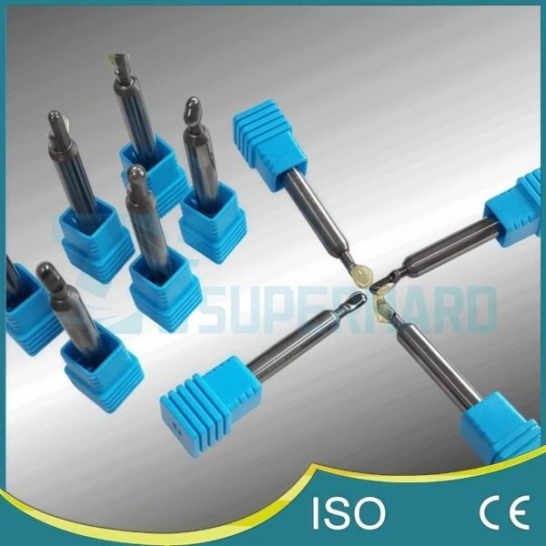
A ball nose end mill6 has a perfectly rounded tip. It’s used for milling 3D contoured surfaces, complex curves, and fillets. It is the go-to tool for mold making and machining complex aerospace components.
| End Geometry | Square End | Corner Radius | Ball Nose |
|---|---|---|---|
| Primary Use | Milling sharp 90° corners, slots, and flat faces. | General-purpose milling, pocketing, and profiling. | 3D contouring, surface milling, and creating fillets. |
| Key Advantage | Creates perfectly square features. | Stronger corners lead to longer tool life and higher feed rates. | Can produce complex, curved surfaces smoothly. |
| Limitation | Corners are weak and prone to chipping. | Leaves a small fillet at the bottom of walls. | Not efficient for creating flat surfaces. |
Shank vs. Brazed Tip Design: Impact on Rigidity and Milling Performance
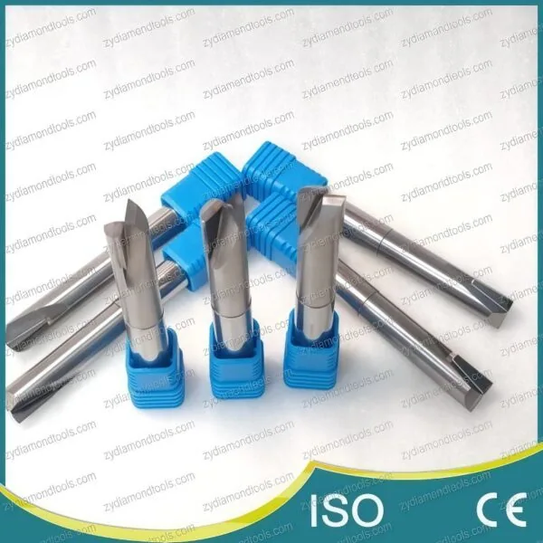
Nearly all PCD end mills you encounter will have a brazed tip design. This means that a small, precisely shaped tip made of PCD is brazed (a type of high-temperature soldering) onto a solid carbide shank (the body of the tool).
Why is this done? It’s the best of both worlds.
- Solid Carbide Shank: Carbide is extremely rigid and excellent at damping vibration. This rigidity is vital in milling to prevent “chatter,”7 a vibration that ruins surface finish and can break the tool. A strong, stable body is the foundation of a good end mill.
- PCD Tip: The PCD provides the incredibly hard and wear-resistant cutting edge exactly where it’s needed.
This hybrid construction provides the toughness and stability of carbide with the unmatched cutting performance of diamond, all while being more cost-effective than making the entire tool out of PCD.
Selecting the Correct PCD Grade for Your Material Abrasiveness
Not all PCD is the same. PCD grades are different recipes of diamond, each with a different average diamond grain size. Think of it like sandpaper—you have coarse grits for heavy removal and fine grits for a smooth finish.
- Coarse Grain PCD (e.g., 25-30 µm): This grade has large diamond crystals. It is extremely tough and highly resistant to abrasion. This makes it the perfect choice for rough milling highly abrasive materials, like high-silicon aluminum or carbon composites. The trade-off is that it cannot hold as sharp an edge.
- Fine Grain PCD (e.g., 2-5 µm): This grade has very small diamond crystals. It is less tough but can be honed to a razor-sharp edge. This is the ideal choice for finishing operations where the goal is a mirror-like surface finish on materials like aluminum alloys.
Important Note: PCD grade names and specifications are not standardized across the industry. A “finishing grade” from one manufacturer may have different properties than one from another. Always consult your tooling supplier’s technical data sheets to select the grade that is specifically engineered for your material and application.
What Milling Strategies Maximize the Performance of PCD End Mills?
Now that you have the right tool, how do you use it correctly to get the best results?
To maximize performance, you must use milling strategies that protect the hard but brittle PCD cutting edge. This involves applying high-speed, low-depth toolpaths, exclusively using climb milling, and employing smooth entry and exit techniques like ramping or helical interpolation to avoid high-impact forces.
Owning a high-performance sports car doesn’t make you a race car driver. You need to know the right techniques—when to accelerate, how to take corners, and how to avoid stress on the engine. The same is true for PCD end mills. Using them with the wrong strategy is like driving a Ferrari in first gear; you’re not getting any of the benefits and you might even damage it.
Applying High-Speed, Low-Depth Toolpaths
The core philosophy behind using PCD end mills is High-Speed Machining (HSM). Instead of taking one deep, slow cut, you take many very shallow, very fast cuts.
Think about sanding a piece of wood. You get a better finish by moving fine-grit sandpaper quickly and lightly over the surface many times, not by pressing down hard with coarse sandpaper. HSM with PCD works the same way.
- High Speed: This refers to a very high surface speed (the speed at which the cutting edge travels over the material). For aluminum, this can be in the range of 1000-3000 m/min.
- Low Depth: This means using a small axial depth of cut (how deep the tool is engaged vertically) and a small radial depth of cut (how far it steps over sideways).
This strategy works because it keeps cutting forces low and consistent. The light cuts generate less heat and put minimal stress on the strong but brittle PCD edge, preventing it from chipping while allowing you to move at incredible feed rates.
A Critical Reminder: The exact speeds, feeds, and depths of cut are highly dependent on the specific PCD grade, the material you’re cutting, the machine’s capability, and the tool holding. The parameters provided here are general guidelines; always start with the cutting data recommended by your tooling supplier and adjust from there.
Climb Milling vs. Conventional Milling: The PCD Advantage
How the tool rotates in relation to its direction of travel is critical. There are two ways to mill: conventional and climb.
- Conventional Milling: The tool rotates against the direction of feed. The chip starts thin, gets thicker, and is thrown out behind the cutter. This method involves a rubbing action as the tooth enters the cut, which creates heat and friction—two things that can damage a PCD edge.
- Climb Milling: The tool rotates with the direction of feed. The cutting edge immediately bites into the material, forming a chip that goes from thick to thin. The chip is then thrown out behind the cutter.
For PCD end mills, climb milling is almost always the required strategy.
Why? Because the thick-to-thin chip formation ensures the cutting force is directed into the workpiece, leading to a smoother cut with less tool pressure. Most importantly, it avoids the rubbing and high-impact entry of conventional milling, which protects the PCD tip from chipping and extends its life dramatically.
| Feature | Climb Milling (Recommended for PCD) | Conventional Milling (Avoid with PCD) |
|---|---|---|
| Tool Rotation | Rotates WITH the direction of travel. | Rotates AGAINST the direction of travel. |
| Chip Formation | Starts thick, ends thin. | Starts thin, ends thin. |
| Tool Entry | A clean “bite” into the material. | A rubbing or “skidding” entry. |
| Effect on PCD | Low impact, directs forces into the part, protects the cutting edge. | High impact and friction, can cause chipping and premature wear. |
| Surface Finish | Generally better. | Can be less ideal due to rubbing. |
Entry and Exit Strategies: Ramping and Helical Interpolation
The most dangerous moment for a PCD end mill is plunging straight into solid material. The flat bottom of the tool hits the workpiece with full force, like a belly flop into a pool. This massive impact can easily fracture the PCD tips.
To avoid this, you must always use a smooth entry strategy.
- Ramping: Instead of plunging straight down, you program the tool to move down at a shallow angle as it moves forward, like walking down a ramp. This gradually engages the cutting edge and keeps the impact forces low and controlled.
- Helical Interpolation: This is the smoothest method of all. The end mill follows a spiral or “corkscrew” toolpath to open up a pocket or hole. It is constantly engaged in a light, sideways cut, which is the ideal condition for a milling tool. Think of it as walking down a spiral staircase instead of jumping off the balcony.
Just as important is the exit. You should program the tool to “arc off” the part rather than stopping the feed while it’s still in contact. This prevents a small “dwell mark” on the surface and ensures a clean disengagement.
Conclusion
Successfully using PCD end mills isn’t about a single secret; it’s about a complete, integrated approach. These are not simple drop-in replacements for carbide tools but are highly specialized instruments that reward a thoughtful process with exceptional performance and cost savings.
By first confirming you have the right application—like abrasive aluminum, composites, or graphite—you set the stage for success. From there, a careful selection of the tool’s features, from its geometry to the specific PCD grade, ensures the end mill is perfectly matched to the task. Finally, implementing the correct strategies, such as high-speed toolpaths and protective entries, unlocks the tool’s full potential. When these three areas align, PCD end mills deliver the speed, tool life, and finish quality that modern manufacturing demands.
References
- carbide end mill1 – An internal blog post comparing the fundamental differences between PCD and traditional carbide cutting tools.
- high-silicon aluminum2 – A ZYDiamondTools article detailing the specific challenges and solutions for machining this abrasive material.
- built-up edge (BUE)3 – A Wikipedia article providing a technical definition and explanation of the built-up edge phenomenon in metal cutting.
- aerospace4 – An internal resource discussing the critical role of PCD tools in the modern aerospace industry.
- detailed comparison between flat, ball nose, and corner radius geometries5 – A focused ZYDiamondTools comparison of flat, ball nose, and corner radius end mill geometries and their ideal uses.
- ball nose end mill6 – A ZYDiamondTools product page for PCD ball nose end mills, showing specifications and applications.
- “chatter,”7 – A Wikipedia page explaining the concept of machining vibrations (chatter) and its effects.
