-
Whatsapp: +86 13526572721
-
Email: info@zydiamondtools.com
-
Address: AUX Industrial Park, Zhengzhou City, Henan Province, China
-
Whatsapp: +86 13526572721
-
Email: info@zydiamondtools.com
-
Address: AUX Industrial Park, Zhengzhou City, Henan Province, China

How to Select and Effectively Use CBN Grooving Tools?

So, how can you master the specific process of using CBN tools for demanding grooving operations?
Effectively using CBN grooving tools requires a three-step approach: first, selecting an insert with the right grade and geometry for the specific groove; second, applying optimal cutting parameters that prioritize chip control within the groove; and third, troubleshooting grooving-specific issues like poor sidewall finish or insert chipping from packed chips.
Selecting the Right CBN Insert for Your Grooving Application
Choosing the right CBN insert is the critical first step toward a successful grooving operation. A grooving tool faces unique stresses compared to a turning tool, and making the wrong choice can lead to chip jamming, poor groove quality, and broken tools.
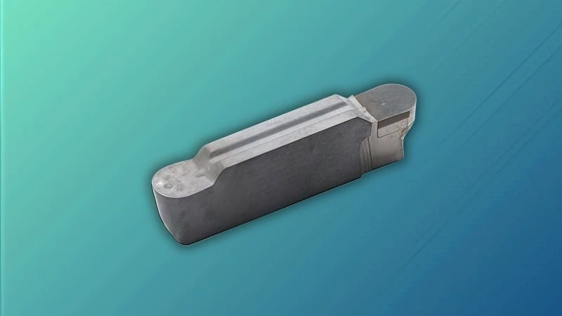
Selecting the right CBN grooving insert involves four key steps: matching the CBN grade to your material’s hardness, deciding between solid and tipped inserts based on grooving forces and stability, choosing the correct geometry for chip control and groove profile, and considering the specific type of grooving operation.
Matching CBN Grade to Workpiece Material and Hardness
First, you must match the tool to the material. A CBN grade refers to the specific recipe used to make the insert, which includes the amount of CBN crystals and the type of ceramic binder holding them together. This choice affects how heat is managed within the confined space of the groove itself.
High CBN Content Grades
High CBN content grades (typically 85-95% CBN) have excellent thermal conductivity. In a continuous grooving operation, this is critical for pulling heat away from the workpiece and preventing thermal damage to the groove’s sidewalls. They are ideal for finishing smooth, uninterrupted grooves in hardened steels (>50 HRC).
- Industry Example: When finishing a deep groove on a hardened steel (62 HRC) transmission shaft, a high CBN content grade allows for high cutting speeds. This creates a clean cut and draws heat away from the newly formed sidewalls, preventing metallurgical damage.
Low CBN Content Grades
Low CBN content grades (typically 45-65% CBN) are tougher due to more ceramic binder. This toughness is essential for interrupted grooving, such as cutting a groove that crosses a keyway or oil hole. They can handle the constant shock of entering and exiting the material without chipping easily, especially when machining abrasive materials like cast iron1.
- Industry Example: Machining a snap ring groove in a cast iron piston that has oil-return slots is a perfect application. A low CBN content grade provides the toughness to handle entering and exiting the cut as it passes over the slots, ensuring the insert corners survive.
Important Note: CBN grade designations like ‘BLC200’ or ‘KB5630’ are unique to each manufacturer. Therefore, you should always consult your tool supplier’s technical guides to find the specific grade they recommend for your material and its hardness.
Solid CBN vs. Tipped CBN: Making the Right Choice
Your next choice is the insert’s construction. This decision hinges on the stability of your setup and the high radial forces inherent in plunge grooving.
This table provides a clear comparison:
| Feature | Solid CBN Inserts | Tipped CBN Inserts |
|---|---|---|
| Best Use Case | Deep plunge grooving or wide grooves where high radial forces demand maximum stability. | Finishing passes in grooves, shallow grooving, and internal grooving with boring bars. |
| Rigidity/Stability | Extremely high. Resists vibration that could cause a tapered or poor-quality groove. | Lower. Best for lighter cuts where deflection forces are minimal. |
| Heat Dissipation | Excellent. The entire insert body pulls heat out of the confined groove. | Good. Heat is managed at the tip, suitable for less demanding grooving cuts. |
| Cost | Higher initial cost. Justified for high-volume, demanding grooving jobs. | Lower initial cost. More economical for general-purpose grooving. |
In short, if you are performing deep, high-volume plunge grooving on a rigid machine, a solid CBN insert provides unmatched stability. For most finishing passes and shallow grooves, the tipped CBN insert is the more economical choice.
Understanding Insert Geometries and Edge Preparations
The shape of the tool is paramount in grooving, as it dictates the groove profile and, most importantly, chip control.
Insert Geometry
The most critical geometric feature is the insert width (W), which must precisely match the desired width of the final groove. Beyond this, look for chipbreaker geometries2. Many grooving inserts have complex shapes molded onto the top surface specifically designed to curl the chip tightly, so it doesn’t become a long, stringy ribbon that gets trapped in the groove. The choice between a flat-bottom and full-radius insert depends entirely on the blueprint’s requirements for the groove’s bottom profile.
Edge Preparation
Edge preparation strengthens the most vulnerable part of a grooving insert: the corners.
- Honed or Sharp Edge: Best for light finishing passes where you are only removing a small amount of material. Reduced cutting forces lead to a better finish on the groove’s floor and sidewalls.
- Chamfered or T-Land Edge: This strong edge is essential for rough grooving, interrupted cuts, or when plunging directly into the material. The T-land reinforces the corners of the insert, preventing them from chipping as they form the groove’s sidewalls.
Considering the Type of Grooving Operation
Finally, the orientation of the groove dictates the toolholding and stability challenges.
- External Grooving: The most stable operation. It allows for robust toolholding, making it easier to combat the radial forces of plunge grooving.
- Internal Grooving (Boring)3: Inherently unstable due to tool overhang. Chip evacuation is the primary challenge, as trapped chips will damage the internal groove surface. Tipped CBN inserts with sharp chipbreakers on specialized boring bars are required.
- Face Grooving: The changing diameter during the cut alters the surface speed. A tough insert is needed to handle these varying conditions, and chip control is crucial to prevent chips from marring the face of the part.
Optimal Cutting Parameters for CBN Grooving
Once you’ve selected the perfect insert, setting the right machine parameters is essential for a clean groove and great chip control.
Optimizing grooving parameters involves setting a high cutting speed to soften the material, using a feed rate that creates manageable, broken chips that don’t jam in the groove, keeping the plunge depth light, and generally running dry to avoid thermal shock.
Getting these parameters right is the difference between a smooth operation and a constant struggle with tangled chips and broken tools.
Recommended Speeds and Feeds for Common Hard Materials
For grooving, cutting speed (Vc) and feed rate (fn) work together to control chip formation. The goal is to produce small, coiled “6” or “9” shaped chips that can be easily evacuated from the groove. Long, stringy chips will get caught, re-cut, and break the tool.
- Cutting Speed generates heat to soften the material for a clean cut.
- Feed Rate directly influences chip thickness and shape. A feed rate that is too low can create a long, thin ribbon, while a proper feed rate helps the chipbreaker form and break the chip correctly.
While exact numbers depend on your specific machine and insert grade, the following table provides a reliable starting point.
| Workpiece Material | Hardness (HRC) | Cutting Speed (m/min) | Feed Rate (mm/rev) |
|---|---|---|---|
| Hardened Steel | 58-65 HRC | 120 – 180 | 0.08 – 0.15 |
| Gray Cast Iron | 190-240 HB | 300 – 700 | 0.10 – 0.25 |
Crucial Reminder: These are starting values. Chip formation is key. If your chips are not breaking, adjust the feed rate and depth of cut before drastically changing the speed. Always begin with the recommendations in your tool supplier’s technical catalog.
The Role of Cutting Depth in Performance
For grooving, the depth of cut (Ap) refers to the plunge depth. Unlike turning, you often cannot cut the full groove depth in a single pass, especially if it’s deep or wide.
- Shallow Grooves: For grooves no deeper than about 50% of the insert width, a single, straight plunge is often acceptable.
- Deep Grooves: To maintain control and ensure proper chip evacuation, peck grooving4 is a highly effective technique. This involves plunging a small amount (e.g., 0.5-1.0 mm), retracting slightly to break the chip, and then plunging again. This prevents the formation of long chips that would otherwise jam in a deep channel.
For finishing passes, a light depth of cut between 0.1 mm and 0.3 mm is used to clean up the groove floor and walls.
Dry vs. Wet Machining: When to Use Coolant
For grooving, the decision to use coolant is a trade-off between protecting the tool from thermal shock and assisting with chip evacuation.
Why Dry Machining is Preferred
Dry machining is the standard for CBN to prevent thermal shock5. A well-designed grooving insert with a proper chipbreaker, combined with optimal parameters, should be able to form and evacuate chips without assistance.
When Coolant is a Necessary Tool
In deep or internal grooving, chip evacuation can become impossible without help. In these specific cases, coolant can be used primarily as a tool to flush chips out of the groove.
- Dimensional Stability: For tight-tolerance grooves, flood coolant keeps the part temperature stable.
- Chip Flushing: In deep internal grooves, a high-pressure jet of coolant aimed directly at the cutting edge can forcefully remove chips and prevent them from jamming.
Warning: If you must use coolant for chip evacuation, it must be a constant, high-volume flood. Intermittent coolant will cause thermal shock and destroy the insert.
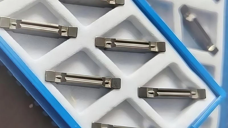
Troubleshooting Common CBN Grooving Problems
Even with the right tool and parameters, problems can arise. Think of this process like a mechanic diagnosing an engine: by looking at the symptoms, you can identify the root cause and apply the correct fix.
Troubleshooting common CBN grooving problems involves identifying the specific issue—be it wear, chipping, or poor groove quality—and applying a targeted solution, often by adjusting parameters to improve chip control or modifying the setup to increase rigidity.
The following guide addresses problems specific to forming a groove, moving beyond generic advice.
Identifying and Solving Rapid Flank Wear
This issue presents as the tool wearing out too quickly at the bottom of its cutting edge. In grooving, this is almost always a sign of inefficient cutting at the groove floor.
| Cause | Solution & Actionable Advice |
|---|---|
| Cutting Speed is Too Low | Increase the cutting speed (Vc). This is the most effective solution. Low speed causes the insert to plow through material at the bottom of the groove, creating friction and wear. |
| Incorrect CBN Grade | Verify your CBN grade selection. Using a tough, low-CBN grade for a smooth finishing pass in a groove can cause abrasive wear. Switch to a high-CBN grade for better performance. |
Preventing Insert Chipping and Catastrophic Failure
Chipping in grooving is often related to the unique stresses of the operation: high radial forces, instability, and, most importantly, chip control.
| Cause | Solution & Actionable Advice |
|---|---|
| Chip Jamming in the Groove | Improve chip control. This is the #1 cause of catastrophic failure in grooving. Adjust the feed rate or depth of cut to change the chip’s shape. Use the peck grooving cycle. |
| Vibration During Plunge Cut | Improve rigidity. Use the shortest tool overhang possible. Ensure the grooving tool is clamped securely and is on the centerline of the part. Vibration will hammer the delicate corners. |
| Interrupted Cut in the Groove | Use a stronger edge preparation. If your groove crosses a hole or keyway, you must use an insert with a chamfered (T-Land) edge to protect the corners from the impact. |
Improving Poor Surface Finish and Dimensional Accuracy
This is where grooving-specific problems are most obvious. The quality of the groove’s floor and its two sidewalls are critical.
Poor Finish on Groove Sidewalls
| Cause | Solution & Actionable Advice |
|---|---|
| Chips Rubbing the Sidewall | Improve chip control. Use an insert geometry designed to curl the chip tightly, pulling it away from the finished wall. A high-pressure coolant jet can also help. |
| Vibration or Tool Deflection | Check rigidity and tool alignment. Any instability will cause the tool to rub against the sidewalls, ruining the finish. Ensure the tool is perfectly on center. |
Incorrect Groove Width or Taper
| Cause | Solution & Actionable Advice |
|---|---|
| Tool Deflection | Reduce cutting forces and improve rigidity. If the groove is wider at the top than the bottom (tapered), your tool is deflecting. Use a lighter depth of cut and ensure the tool is short. |
| Worn Insert Corners | Index or replace the insert. As the corners of the insert wear down, the final groove will become undersized or tapered. |
Conclusion
Mastering CBN grooving is not about general machining knowledge, but about understanding and controlling the unique challenges of cutting a confined channel. Success hinges on a systematic process focused on the specifics of the operation. By methodically selecting a tool for the groove’s profile and chip control, carefully applying parameters to manage chip evacuation, and knowing how to troubleshoot issues like sidewall finish and chip jamming, you can transform a challenging operation into a predictable and efficient process. This targeted approach is the key to unlocking the full potential of CBN tools in your most demanding grooving applications.
References
- Cast iron1 – A ZYDiamondTools guide specifically on the challenges and solutions for machining hard cast iron with PCBN tools.
- Chipbreaker geometries2 – A ZYDiamondTools article focused on the selection and application of CBN chipbreaker inserts for better machining performance.
- Internal Grooving (Boring)3 – A ZYDiamondTools guide to selecting and using PCBN boring bars, relevant to the challenges of internal machining.
- Peck grooving4 – A technical guide from G-Code Tutor explaining the G75 grooving cycle, the CNC programming method used for peck grooving.
- Thermal shock5 – A ScienceDirect topic page defining thermal shock and explaining the material science behind why it occurs.
