-
Whatsapp: +86 13526572721
-
Email: info@zydiamondtools.com
-
Address: AUX Industrial Park, Zhengzhou City, Henan Province, China
-
Whatsapp: +86 13526572721
-
Email: info@zydiamondtools.com
-
Address: AUX Industrial Park, Zhengzhou City, Henan Province, China

How to Choose the Right Cutting Tool for Your Machining Job

What does it really take to choose the perfect cutting tool for a machining job?
Choosing the right cutting tool requires a systematic evaluation of five key factors. You must first identify your specific machining operation to select the basic tool type. Next, you directly match a tool material to your specific workpiece, which is the most critical pairing. Afterward, you refine this choice by specifying the tool’s geometry, adding a performance-enhancing coating, and finally, validating your selection against practical constraints.
What Is Your Specific Machining Operation?
So, how does the job you need to do determine the basic shape of the tool you’ll use?
The specific machining operation you are performing dictates the fundamental type of cutting tool required. Each operation, from creating flat surfaces to drilling holes, uses a tool uniquely designed for that task. For instance, milling uses rotating end mills to cut material, while turning uses stationary inserts on a rotating workpiece. Consequently, choosing the correct tool type is the first and most critical step in the selection process.
Before you can consider factors like tool material or coatings, you must first match your tool to the task at hand. Think of it like a kitchen; you wouldn’t use a rolling pin to chop vegetables. Similarly, in machining, the operation defines the tool.
Selecting Tools for Milling Operations (End Mills)
Milling is a process where a rotating cutter removes material from a stationary workpiece. Imagine a sculptor carefully carving a block of marble; milling does the same, but with metal or plastic and incredible precision. The primary tool for this job is the end mill.
An end mill is a cylindrical cutter with sharp teeth on its sides and end. Unlike a standard drill bit that is designed only to plunge straight down, an end mill is engineered to cut sideways (peripheral milling) as well as plunge downwards (plunging). This versatility allows it to perform a wide range of tasks.
Common Milling Applications
- Facing: Creating a perfectly flat, smooth surface on the top of a workpiece. This is often the very first operation to prepare a block of raw material.
- Slotting: Cutting a channel or groove into a part. For example, creating a keyway in a shaft requires a precise slotting operation.
- Profiling: Cutting around the outside perimeter of a part to create its final shape.
- Pocketing: Removing material from the inside of a part to create a cavity or “pocket.” A classic example is machining the housing for electronic components, which requires a precise, hollowed-out space.
Essentially, if your goal is to create complex 2D or 3D shapes, pockets, or flat surfaces on a stationary part, an end mill is your starting point.
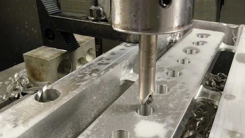
Selecting Tools for Drilling and Holemaking (Drills & Reamers)
Drilling is one of the most fundamental machining operations. Its purpose is simple: to create a round hole in a workpiece. The most common tool for this job is the twist drill, easily recognized by its helical flutes that evacuate chips out of the hole as it cuts.
However, is just creating a hole enough? Sometimes, a hole needs to be perfectly round and have an exact diameter to fit a bearing or a precision pin. A standard twist drill often leaves a slightly rough finish and may not produce a perfectly sized hole. This is where a reamer comes in.
Drill vs. Reamer: A Critical Distinction
Think of it as a two-step process for achieving perfection.
- Drilling: The first step is to use a twist drill to create the initial hole. This hole is intentionally made slightly undersized. For instance, to get a final 10mm hole, you might first drill a 9.8mm hole.
- Reaming: The second step is to use a reamer. A reamer is a highly precise tool designed to remove only a tiny amount of material. It follows the drilled hole, widening it to the exact final diameter while creating a very smooth internal finish.
Therefore, for general-purpose holes, a drill is sufficient. But for high-precision applications where size and finish are critical, the process is drill first, then ream.
Selecting Tools for Turning Operations (Lathe Inserts)
Turning operations are fundamentally different from milling. Here, the workpiece rotates at high speed while a stationary cutting tool removes material. Imagine a potter shaping a lump of clay on a spinning wheel; a lathe shapes a metal bar in much the same way.
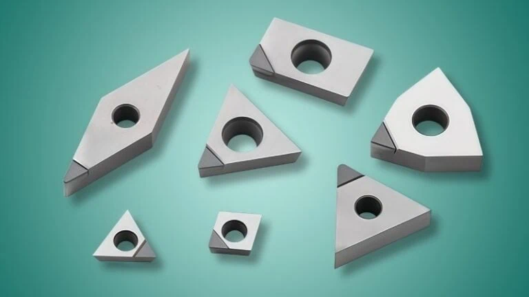
The tools used for turning are typically inserts held in a tool holder. An insert is a small, replaceable, and often indexable1 tip made of very hard material.
Industry Analogy: Think of the insert and tool holder system like a modern razor. Instead of throwing away the entire handle when the blade gets dull, you simply replace the small, inexpensive blade cartridge. In turning, you don’t replace the entire steel tool holder; you just unclamp and replace the small, worn insert, making it highly economical.
These inserts come in a vast array of shapes (triangular, square, diamond) and sizes, each designed for a specific task like facing the end of a part, turning down its diameter, or cutting grooves. The shape of the insert directly determines the type of cuts you can make.
Selecting Tools for Threading (Taps & Thread Mills)
Creating threads for screws and bolts is another essential operation. This can be done in two primary ways: using a tap or a thread mill.
Taps: The Traditional Choice
A tap is a tool that looks like a screw and is designed to cut internal threads in a pre-drilled hole. As the tap is turned into the hole, its sharp edges cut the thread pattern. It’s a straightforward process but has one major drawback: because the tap is the same size as the thread, it has a high risk of breaking off inside the hole, which can be very difficult to remove.
Thread Mills: The Flexible CNC Solution
A thread mill is a cutter that moves in a helical path inside the hole to form the threads. It is always smaller in diameter than the hole itself. This method offers significant advantages.
- Flexibility: A single thread mill can create threads of various diameters, as long as the pitch (distance between a given point on a thread and the corresponding point on the next thread) is the same.
- Safety: Since the tool is smaller than the hole, it’s far less likely to get stuck and break.
- Versatility: It can create both internal and external threads.
The choice between them often comes down to the machine and the application.
| Feature | Tapping | Thread Milling |
|---|---|---|
| Process | Tool cuts by driving straight in | Tool cuts by orbiting in a helical path |
| Tool Size | Same as the thread diameter | Smaller than the thread diameter |
| Risk | Higher risk of tool breakage | Very low risk of tool breakage |
| Flexibility | One tool for one specific thread size | One tool for many diameters (same pitch) |
| Requirement | Can be done on basic machines | Requires a capable CNC machine |
A Note on Other Specialized Operations (Grinding, Boring, etc.)
While milling, turning, and drilling are the most common operations, the world of machining is vast. Other specialized processes exist for specific needs.
- Boring: This operation is used to enlarge an existing hole to achieve a precise diameter and straightness, often using a single-point cutting tool on a lathe or milling machine.
- Grinding: Instead of a sharp cutter, this process uses a rotating abrasive wheel to remove very small amounts of material, producing extremely accurate dimensions and excellent surface finishes.
- Broaching: A special toothed tool called a broach is pushed or pulled through a hole or across a surface to create non-circular shapes, like a square hole or internal keyways, in a single pass.
These operations require their own unique tools and are typically used when standard methods can’t achieve the required precision or shape.
Matching Tool Material to Your Workpiece
After identifying your operation, the most critical question is matching your tool material to your workpiece material. Each material presents unique challenges, and the right tool material is the key to overcoming them for efficient, high-quality machining.
This section provides direct recommendations, pairing common workpiece materials with the best tool material choices, from general-purpose options to high-performance solutions.
For General Steels and Stainless Steels
Primary Challenge: High operating temperatures and a tendency to work harden. Steel, and especially stainless steel, generates immense heat during cutting and requires a tool that can maintain its sharp edge under extreme thermal load.
- Primary Recommendation: Coated Solid Carbide. This is the modern industry standard. Carbide’s excellent hot hardness allows it to stay hard even when glowing red hot. A coating like TiAlN, AlTiN, or AlCrN acts as a thermal barrier, further protecting the tool and allowing for significantly faster cutting speeds and longer life.
- Secondary/Budget Option: Coated High-Speed Steel (HSS). For lower-speed operations, on less rigid machines, or when cost is a primary concern, a coated HSS tool can be effective. Its natural toughness makes it resistant to chipping, but it must be run at much slower speeds compared to carbide to avoid overheating.
For Aluminum Alloys and Other Soft Metals
It’s crucial to differentiate between standard aluminum alloys and high-silicon alloys, as they require vastly different tooling solutions.
- For Standard Aluminum (e.g., 6061) and Copper/Brass:
Primary Challenge: “Gummy” behavior and chip welding (Built-Up Edge – BUE2). The primary goal is to achieve a clean shear without material sticking to the tool.
Recommendation: Uncoated, Polished Solid Carbide. The best choice is often a tool with an ultra-sharp, highly polished cutting edge (a “bright finish”). This incredibly smooth surface prevents the gummy chips from getting a foothold. In this case, the sharpness of the edge is often more critical than the added hardness of a coating. - For High-Silicon Aluminum3 Alloys (e.g., A390):
Primary Challenge: Extreme abrasion. The hard silicon particles embedded in the aluminum act like sandpaper, causing rapid wear on carbide tools.
Recommendation: PCD (Polycrystalline Diamond). This is where PCD is indispensable. Its exceptional abrasion resistance, being the hardest of all tool materials, allows it to machine high-silicon aluminum at high speeds with a tool life that can be 50 to 100 times longer than carbide. It is the standard in the automotive industry for machining components like pistons, engine blocks, and cylinder heads.
For Cast Iron
The tooling choice for cast iron depends heavily on its hardness and microstructure.
- For Grey Cast Iron:
Primary Challenge: Moderate abrasiveness due to graphite content.
Recommendation: Coated Carbide or Ceramics. A wear-resistant coated carbide grade is the reliable workhorse. For very high-speed finishing, Ceramic tools can offer superior productivity due to their extreme hot hardness. - For Hard, Chilled, or White Cast Iron:
Primary Challenge: Extreme hardness and high abrasiveness4 due to the presence of iron carbides (cementite).
Recommendation: CBN (Cubic Boron Nitride). For these difficult-to-machine irons, CBN is the optimal solution. Its high hardness and thermal stability allow it to effectively cut these materials where carbide would rapidly fail, providing excellent tool life in applications like roll manufacturing and pump components.
For Hardened Steels, Superalloys, and Titanium
Primary Challenge: Extreme hardness (for hardened steels) and a combination of high heat generation, work hardening, and chemical reactivity (for superalloys and titanium).
- For Hardened Steels (45 HRC5 and above):
Recommendation: CBN (Cubic Boron Nitride). CBN is the definitive choice for “hard machining6.” It allows for the turning, milling, and boring of heat-treated steels, often replacing slower and more costly grinding operations. It maintains its hardness under the intense heat and pressure of cutting these materials. - For Titanium and Superalloys (e.g., Inconel):
Recommendation: Specialized Coated Carbide. These materials require specially engineered carbide grades that balance toughness with hot hardness, paired with advanced, heat-resistant coatings. The cutting speeds must be managed carefully to avoid excessive heat and work hardening.
For Composites and Abrasive Non-Metals
Primary Challenge: Extreme abrasiveness and a tendency for delamination or melting.
- For Carbon Fiber (CFRP), Fiberglass (GFRP), and other Abrasive Composites:
Recommendation: Diamond Tooling (PCD or Diamond-Coated). The abrasive fibers in these materials will destroy conventional tools almost instantly. PCD provides the ultimate tool life and part quality. Diamond-coated carbide tools are another excellent, slightly more cost-effective alternative that still offers vastly superior performance over uncoated carbide. - For General Plastics:
Recommendation: Sharp, Uncoated Tools (HSS or Carbide). The primary challenge with plastics is their low melting point. The goal is a clean “shearing” action, not pushing. A very sharp edge is key, making uncoated HSS or a polished, sharp-edged carbide tool the preferred choice. Here, the tool’s geometry is often more critical than its material.
If you are looking for or need to purchase superhard material tools, please refer to our PCD & PCBN tools product catalog7.
What Tool Geometry Details Should You Specify?
How can the actual shape of a cutting tool dramatically change the way it cuts?
The geometry of a cutting tool—its shape, angles, and number of cutting edges—directly controls chip formation, surface finish, and the stability of the cut. Key details like the flute count determine how much material is removed with each rotation and how efficiently chips are cleared. Furthermore, angles like the helix and rake dictate the cutting forces and the direction in which chips flow away from the workpiece.
Once you’ve selected your tool material, you must refine your choice by specifying its geometry. To understand this, we’ll explore three key geometric areas. It is crucial to recognize that the first two features, Flute Count and Helix Angle, are primary characteristics of rotating tools like end mills and drills. The third feature, Tip Geometry, is a universal concept that applies to all major tool types, including stationary turning inserts, and we will use the end mill as a clear example to understand its importance.
Flute Count: Matching Chip Evacuation and Finish Quality
The flutes are the helical grooves on the side of a tool like an end mill. The number of flutes is one of the most important geometric choices you will make, as it creates a critical trade-off between chip removal and surface finish.
Industry Analogy: Think of the flutes as lanes on a highway for chips. A tool with fewer flutes (like a 2-lane road) has very wide, deep lanes, allowing large “trucks” (big, gummy chips from soft materials) to pass through easily. A tool with many flutes (like a 6-lane highway) has narrower lanes, which slows down big trucks but allows many more “cars” (small, hard chips) to create a smoother, faster flow of traffic (a better surface finish).
The general rule is simple: use fewer flutes for soft, gummy materials and more flutes for hard, brittle materials.
| Flute Count | Primary Application | Key Advantage | Key Disadvantage |
|---|---|---|---|
| 2-Flute | Soft Metals (Aluminum), Plastics, Wood | Maximum chip clearance prevents clogging | Weaker tool core, can leave a rougher finish |
| 3-Flute | General-Purpose Milling (Slots/Pockets) | A versatile balance of strength & chip room | Not fully specialized for either extreme |
| 4-Flute | Harder Materials (Steels) and Finishing | Stronger tool core & smoother surface finish | Less space for chips, can clog in deep cuts |
| 5+ Flutes | High-Speed Finishing of Hard Metals | Excellent surface finish & very stable cut | For very light finishing passes only |
This is why, as we discussed in the previous section, machining gummy aluminum almost always calls for a 2-flute tool. Without that massive amount of space for chip evacuation, the tool would clog and fail immediately.
The Role of the Helix and Rake Angles
Beyond the number of flutes, the specific angles of the cutting edges fine-tune how the tool interacts with the material. Two of the most important are the helix and rake angles.
Helix Angle: The “Spiral” of the Cut
The helix angle is the angle of the flute’s spiral. A low helix angle results in a straighter flute, while a high helix angle creates a more aggressive spiral.
- Low Helix Angle (~30°): This creates a stronger cutting edge and is better for roughing tougher materials. The cutting action is more direct and forceful, like a chop.
- High Helix Angle (~45°): This creates a softer, smoother cutting action, like slicing with a sharp knife. It reduces cutting pressure and is excellent at “lifting” chips up and out of the cut, making it ideal for finishing passes and for materials like aluminum.
Different manufacturers offer a variety of helix angles for specific materials. It is always a good practice to check a supplier’s catalog to see their recommendation for your particular application.
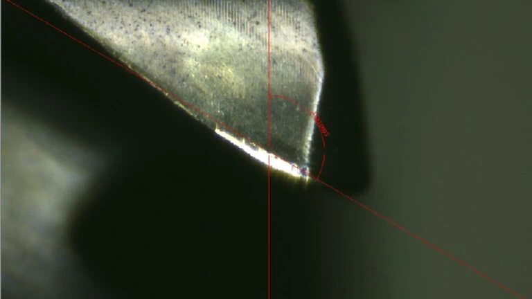
Rake Angle: The “Sharpness” of the Edge
The rake angle describes the angle of the cutting face relative to the workpiece. Think of it as how much the cutting edge “leans” into the cut.
- Positive Rake: The cutting face leans back, creating a very sharp edge that slices the material. This requires less force, reduces heat buildup, and is the standard choice for soft materials like aluminum, copper, and plastics.
- Negative Rake: The cutting face leans forward. This creates an incredibly strong but less sharp edge that essentially plows through the material. This geometry is reserved for very hard or brittle materials (like those cut with ceramic tools) where edge strength is more important than sharpness.
Choosing the Right Tip Geometry (Flat, Ball, or Corner Radius)
The very tip of the tool determines the shape of the surface it leaves behind. As mentioned, this concept is universal, but the examples from end mills are the easiest to visualize.
Square (Flat) End Mills
As the name suggests, these tools have a perfectly flat bottom with sharp 90-degree corners. They are used for any application that requires a sharp corner between a wall and a floor, such as milling a standard pocket or facing the top of a part. Their primary weakness is that these sharp corners are fragile and prone to chipping under stress.
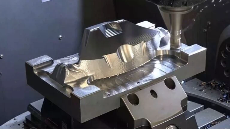
Ball End Mills
These have a fully rounded cutting end, creating a hemispherical shape. Ball end mills are the standard for producing complex, three-dimensional contoured surfaces. Have you ever seen the intricate molds used to make car parts or consumer products? Those flowing, organic shapes are almost always created with ball end mills.
Corner Radius (Bull-Nose) End Mills
A corner radius end mill is a hybrid: it’s a flat-bottomed tool, but the sharp, fragile corners have been replaced with a small, rounded corner. This single change provides two massive benefits:
- Increased Strength: Rounding the corner distributes cutting forces over a larger area, dramatically strengthening the most vulnerable part of the tool. This significantly increases tool life and reduces the risk of chipping, especially during heavy roughing.
- Improved Part Strength: In many engineering applications, sharp internal corners on a part create stress points that can lead to cracks. Leaving a small, rounded fillet with a corner radius tool can make the final part stronger.
This principle of strengthening a tool’s point of contact is universal. For example, turning inserts have a specified “nose radius,” and drills have different “point angles” (e.g., 118° vs. 135°). Both are critical tip geometry features that serve the same functions: enhancing tool strength and influencing the final surface quality.

How Do Tool Coatings Affect Performance and Longevity?
How can a microscopic layer, thinner than a human hair, make a cutting tool so much better?
Tool coatings are micro-thin ceramic layers applied to a tool’s surface that dramatically enhance its performance and lifespan. These coatings act as a protective barrier, providing increased hardness for wear resistance, improved lubricity to reduce friction, and a thermal shield against high cutting temperatures. This allows a coated tool to cut faster, last significantly longer, and produce better surface finishes compared to an uncoated tool.
Think of a cutting tool as an athlete. The base material (like carbide) is the athlete’s strength and training. The coating is the advanced technical gear—the slick swimsuit that reduces drag or the heat-wicking fabric that keeps them cool under pressure. It provides a critical performance edge.
Common Coating Types and Their Benefits
While there are dozens of specialized coatings, most fall into a few major families. Each coating offers a different blend of three key benefits: Hardness, Lubricity (slipperiness), and Heat Resistance.
The table below breaks down some of the most common ceramic-based coatings.
| Coating | Full Name | Key Properties | Primary Application | Common Color |
|---|---|---|---|---|
| TiN | Titanium Nitride | Good Hardness, High Lubricity | A general-purpose “starter” coating, great for HSS tools and tapping | Gold |
| TiCN | Titanium Carbonitride | Very High Hardness, Excellent Wear Resistance | Good for abrasive or tough materials at moderate speeds | Blue-Grey to Violet |
| TiAlN / AlTiN | Titanium Aluminum Nitride | Excellent Hot Hardness, Good Hardness | The workhorse for high-speed machining of steels, stainless, and alloys | Violet-Black |
| AlCrN | Aluminum Chromium Nitride | Extreme Hot Hardness, Very Smooth | High-performance milling in difficult or heat-generating materials | Steel Grey |
Understanding the Key Ceramic Coatings
- TiN (The Original Gold Standard): This is one of the first major PVD (Physical Vapor Deposition) coatings. Its gold color is iconic. While newer coatings have surpassed its heat resistance, TiN’s excellent lubricity and good hardness make it a fantastic, cost-effective choice for drills, taps, and general-purpose milling.
- TiAlN / AlTiN (The High-Temp Champions): These are the most popular coatings for high-performance CNC machining today. Their magic lies in the aluminum content. As the tool heats up during cutting, the aluminum forms a microscopic layer of aluminum oxide—the same material as sapphire—at the cutting tip. This acts as a regenerative heat shield. The hotter it gets, the better it protects itself, which is why it excels in the high-heat conditions of cutting steel and stainless steel.
Important Note: The world of coatings is complex and highly competitive. The exact performance of a coating like TiAlN can vary significantly based on the manufacturer’s proprietary formula and application process. Always trust the tool supplier’s recommendation for which of their specific coatings is best suited for your material.
Diamond Coatings: The Ultimate in Abrasion Resistance
Beyond ceramics, diamond coatings8 represent the peak of wear resistance for specific applications. Applied via processes like CVD (Chemical Vapor Deposition), this is a layer of pure, micro-crystalline diamond on a carbide tool. It is different from the solid PCD material discussed earlier.
- Key Benefits: Unmatched hardness and an extremely low coefficient of friction (it’s incredibly “slippery”). This makes it the ultimate defense against abrasive wear and material sticking.
- Ideal Applications:
- Graphite Machining: This is the primary and most critical application, used for creating EDM electrodes where tool wear must be minimal.
- Abrasive Composites: Excellent for achieving long tool life and clean cuts in CFRP, GFRP, and other composites.
- High-Silicon Aluminum: Provides a durable, sharp edge that resists the abrasive silicon particles.
- Crucial Limitation: Just like PCD, diamond coatings must never be used to machine steel or other ferrous materials. The high heat generated from cutting steel causes a chemical reaction that dissolves the carbon structure of the diamond, leading to immediate coating failure.
Deciding if a Coated Tool is Worth the Investment
So, with all these options, do you always need a coated tool? Not necessarily. The decision comes down to a simple cost-benefit analysis.
The Case for Coated Tools: When Performance Pays
In many scenarios, the higher initial cost of a coated tool pays for itself many times over.
- Production Machining: If you are making hundreds or thousands of parts, the math is easy. A coated tool might cost 30% more, but if it lasts twice as long and allows you to run 50% faster, the reduction in machine time and tool changes results in a significantly lower cost per part.
- Machining Difficult Materials: When cutting tough, heat-generating, or abrasive materials (like stainless steel, titanium, or composites), a coating is not a luxury; it is a necessity. An uncoated carbide tool would fail very quickly, making the job impractical or impossible.
- Achieving a Superior Finish: The high lubricity of coatings reduces friction. This prevents the “built-up edge” that is common when machining sticky materials and results in a smoother, cleaner surface finish on your final part.
The Case for Uncoated Tools: When to Keep It Simple
Despite the benefits, there are times when an uncoated tool is the better choice.
- Machining Standard Aluminum: This is the most common exception. Often, the best tool for aluminum is an uncoated solid carbide tool with highly polished flutes (often called a “bright finish”). Why? Aluminum requires an ultra-sharp cutting edge to prevent its gummy chips from sticking. Some coatings, as thin as they are, can slightly round that microscopic edge, which can be counterproductive.
- Low-Volume or Prototype Work: If you are only making one part in a basic material like mild steel, the performance boost from a premium coating may not justify the extra expense. A simple, uncoated HSS or carbide tool will often suffice.
- When Cost is the Only Factor: In some maintenance or repair situations where getting the job done is more important than speed or perfection, a basic, inexpensive uncoated tool is a perfectly reasonable choice.

Final Practical Considerations
Even an ideal cutting tool on paper must be validated against real-world factors.
A theoretically perfect tool must be validated against three final practical checks: your machine’s capabilities, your production volume, and your machining strategy. Your machine’s horsepower, speed (RPM), and rigidity limit which tools you can effectively use. Furthermore, the balance between tool cost and the number of parts you are making determines what is economically feasible. Finally, your strategy—whether you are roughing away large amounts of material or taking fine finishing passes—dictates a completely different approach to tool selection.
Think of this as the final inspection before a flight. You’ve designed the perfect plane (your tool choice), but now you must check the weather, the runway conditions, and the flight plan (your machine, your budget, and your strategy). These practical realities will determine if your “perfect” choice is truly the best choice for the job.
Matching the Tool to Your Machine’s Capabilities (HP, RPM, and Rigidity)
A cutting tool is only as good as the machine running it. A high-performance tool in a low-performance machine is a wasted investment.
Industry Analogy: You can buy the most advanced racing tires in the world, but if you put them on a family minivan, you’ll never win a race. To unlock the tires’ potential, you need a race car with a powerful engine and a stiff chassis. The same is true for your tool (the tires) and your machine (the car).
Horsepower (HP) and RPM
Every cut requires power. A large-diameter tool removing a lot of material from steel requires significant horsepower. If you choose a tool that is too aggressive for your machine’s spindle motor, the machine will stall or bog down. Conversely, many modern carbide tools are designed for extremely high RPM (revolutions per minute). If your machine has a lower RPM limit, you cannot take advantage of the tool’s speed capabilities, and a less expensive HSS tool might be a more logical choice.
Rigidity: The Unsung Hero
Rigidity is arguably the most important machine characteristic. It is the machine’s ability to resist bending and vibration while under the heavy load of a cut.
- Low Rigidity: Lighter-duty machines, like hobby CNC routers or older manual mills, have lower rigidity. Using an aggressive tool on these machines will cause chatter—a destructive vibration that leaves a terrible surface finish and can quickly destroy the cutting tool.
- High Rigidity: Massive industrial machines are incredibly heavy and stiff. Their high rigidity allows them to handle the immense cutting forces generated by large tools running at high speeds without vibrating.
Therefore, your machine’s rigidity dictates how aggressively you can cut and, by extension, which tools you can effectively use.
Balancing Tool Cost Against Your Production Volume
The “best” tool is not always the most expensive one. The right choice depends heavily on the economics of your specific job.
The Economics of Single Parts and Prototypes
When you are making only one or two parts, your main costs are your time for setup and programming, not the tool itself. The goal here is reliability. It is often wiser to choose a more conservative, less expensive tool and run it at slower, safer speeds. Breaking your only tool on a one-off prototype is a costly mistake that can halt a project.
The Economics of High-Volume Production
In a production environment, the calculation is completely different. The goal is to achieve the lowest possible cost-per-part. Here, a premium, expensive tool is often the most economical choice.
Why? Because a high-performance tool allows for faster cycle times and has a much longer life, reducing the frequency of tool changes.
| Metric | Tool A (Standard Coated) | Tool B (Premium Coated) |
|---|---|---|
| Tool Cost | $25 | $55 |
| Tool Life | 150 parts | 600 parts |
| Cycle Time per Part | 90 seconds | 60 seconds |
| Tool Cost per Part | $0.17 | $0.09 |
| Result | – | Nearly half the tool cost & 33% faster production. |
As you can see, investing in better tooling for production runs directly translates to higher profit margins.
Differentiating Between Roughing and Finishing Strategies
Finally, machining is almost never done in a single step. It is a two-part strategy, and you need a different tool for each stage.
Industry Analogy: This is like sculpting a statue from a block of marble. First, the sculptor uses a large hammer and chisel to quickly remove big chunks of stone and create the basic form. This is roughing. Afterward, they switch to small files, rifflers, and sandpaper to create the fine details, smooth curves, and polished surface. This is finishing.
Roughing: The Goal is Material Removal Rate (MRR)
The only objective of a roughing pass is to remove as much material as possible, as quickly as possible.
- Tool Characteristics: Roughing tools are built for strength and toughness. They often have fewer flutes to clear large chips and a corner radius to prevent the tool’s corners from chipping under heavy load. The surface finish they leave behind is not important.
Finishing: The Goal is Accuracy and Surface Quality
A finishing pass removes only a tiny amount of material. Its sole purpose is to produce the final, precise dimension and the desired smooth surface finish.
- Tool Characteristics: Finishing tools are designed for precision, not brute force. They often have more flutes for a smoother cutting action and a geometry optimized for low cutting pressure and high accuracy.
Your machining strategy dictates your tool choice. You must select a tough, durable tool for your roughing strategy and a separate, precise tool for your finishing strategy. Using the wrong tool for the job will lead to either a broken tool or a poor-quality part.
Conclusion
Choosing the right cutting tool is not a single decision but a logical, layered process. By systematically working through these key factors, you can move from uncertainty to confidence. Start by identifying your operation to pick the right tool family. Then, directly match your tool material to your workpiece to find the most effective solution. Refine this choice by selecting the optimal geometry and adding a performance-enhancing coating. Finally, validate your selection against the real-world constraints of your machine, your budget, and your machining strategy. Following this structured approach will empower you to make smarter, more effective, and more economical tooling decisions for every job you run.
References
- indexable1 – ZYDiamondTools article explaining the economic and flexible advantages of indexable PCD & CBN inserts.
- Built-Up Edge – BUE2 – Wikipedia article defining and explaining the metallurgical phenomenon of the built-up edge in metal cutting.
- High-Silicon Aluminum3 – A ZYDiamondTools guide to solving the challenges of machining high-silicon aluminum with PCD tooling, featuring real-world case studies.
- Extreme hardness and high abrasiveness4 – A comprehensive guide from ZYDiamondTools on how to successfully machine hard cast iron using PCBN tools.
- HRC5 – Wikipedia’s detailed explanation of the Rockwell scale, a common method for measuring material hardness.
- hard machining6 – A ZYDiamondTools article explaining the process of hard turning and comparing it to traditional grinding.
- PCD & PCBN tools product catalog7 – The main product category page on ZYDiamondTools for a full range of PCD (Polycrystalline Diamond) and PCBN (Polycrystalline Cubic Boron Nitride) cutting tools.
- diamond coatings8 – A ZYDiamondTools guide explaining diamond coating technology and how to choose the right solution for your needs.