-
Whatsapp: +86 13526572721
-
Email: info@zydiamondtools.com
-
Address: AUX Industrial Park, Zhengzhou City, Henan Province, China
-
Whatsapp: +86 13526572721
-
Email: info@zydiamondtools.com
-
Address: AUX Industrial Park, Zhengzhou City, Henan Province, China

How Do You Select the Right PCD Tools for Optimal Roll Machining Performance?

So, how exactly do you go about selecting and using PCD tools to get the best results when machining rolls?
Selecting the right PCD tools for optimal roll machining involves understanding why PCD excels (hardness, wear resistance), knowing the key types available (inserts, notchers, mills), matching the tool (grade, geometry) to the specific roll material and task, and applying best practices during use (correct parameters, rigid setup, wear monitoring).
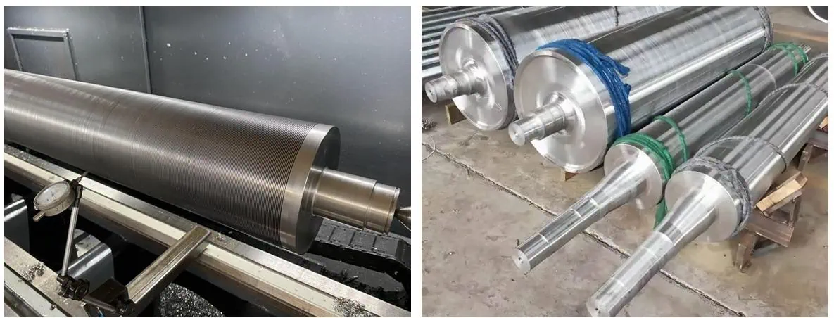
Why Choose PCD for Your Roll Machining Needs?
PCD (Polycrystalline Diamond) tools offer significant advantages for roll machining primarily due to their exceptional hardness and wear resistance. This translates directly into longer tool life, the ability to maintain tight tolerances for superior surface finishes, and the capability to run at much higher cutting speeds compared to traditional carbide or even CBN tools in certain applications, ultimately boosting productivity and reducing overall costs.
Unmatched Hardness and Wear Resistance Explained
Imagine trying to cut something very rough, like sandpaper, over and over again. Regular scissors would get dull quickly, right? PCD tools are like having scissors with diamond edges. PCD stands for Polycrystalline Diamond. It’s made by fusing tiny, man-made diamond particles together under extreme heat and pressure (a process known as sintering1), creating a cutting edge that is incredibly hard – much harder than the standard carbide tools often used in machining.
Now, think about machining industrial rolls, especially those made from tough materials like Tungsten Carbide (TC) or chilled cast iron. These materials are highly abrasive, meaning they wear down tools very fast. Because PCD is so hard, it strongly resists this abrasive wear. This means:
- The cutting edge stays sharp much longer. A sharp edge cuts cleanly and accurately.
- The tool holds its size and shape. This is crucial for making sure the roll dimensions are precise every single time.
This exceptional wear resistance is perhaps the single biggest reason PCD is chosen for demanding roll machining jobs. It can often last significantly longer, sometimes tens of times longer, than carbide tools in the same application, especially when machining very hard or abrasive roll surfaces.
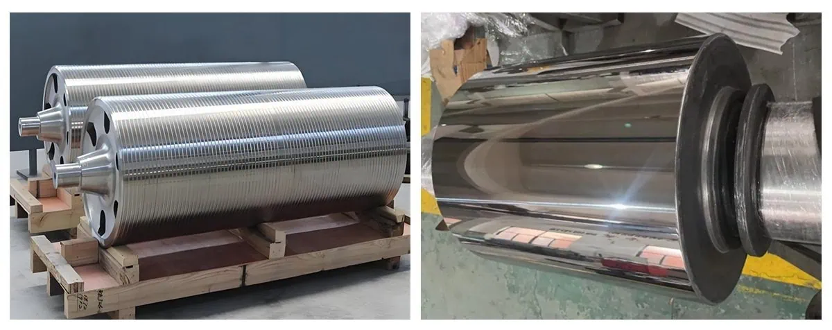
Achieving Superior Surface Finish Quality on Rolls
What does a super sharp, long-lasting cutting edge mean for the roll itself? It means a smoother, higher-quality surface finish.
When a cutting tool starts to dull, it doesn’t cut cleanly anymore. It might start to push or tear the metal instead of shearing it smoothly. This leaves behind a rougher surface with tiny imperfections. For many types of rolls, like those used in printing presses, steel mills for producing high-gloss sheets, or foil production, the surface finish is critical for the final product quality.
PCD tools help achieve excellent surface finishes because:
- They maintain a keen cutting edge: This ensures a clean shearing action.
- PCD has low friction: Material being cut is less likely to stick to the tool edge (known as built-up edge), which can mar the surface.
Using PCD can help manufacturers achieve very low surface roughness (Ra) values consistently, ensuring the rolls perform their function perfectly. A smooth, precisely machined roll surface often translates directly to higher quality in the materials processed by those rolls.
Enabling Higher Cutting Speeds and Boosting Productivity
Because PCD is extremely hard and can handle heat well (it conducts heat away quickly), you can often run machines much faster when using PCD tools compared to carbide. Think of it like having a race car engine versus a regular car engine – the race car engine is built to perform safely at much higher speeds.
What does running faster mean in a workshop?
- Faster Material Removal: You can cut away the needed material from the roll in less time.
- Shorter Cycle Times: Each step of the machining process takes less time, so the whole job finishes sooner.
- Increased Throughput: You can machine more rolls in the same amount of time (e.g., per shift).
This boost in productivity is a major advantage. While the achievable cutting speeds depend heavily on the specific roll material, the machine’s capability, and the PCD tool’s specifications (always consult supplier recommendations for the right parameters), the potential for significantly higher speeds is a key reason engineers turn to PCD. For instance, re-profiling large, worn work rolls in a steel mill can be done much quicker using PCD tooling compared to traditional methods, getting the mill back online faster.
The Benefit of Extended Tool Life and Reduced Downtime
We talked about PCD’s wear resistance keeping the tool sharp longer. This directly leads to much longer tool life. A tool that lasts longer doesn’t need to be changed as often.
Why is this important?
- Less Machine Downtime: Every time a machine stops to change a tool, it’s not producing anything. Fewer tool changes mean the machine runs for longer stretches.
- Reduced Operator Intervention: Operators spend less time changing tools and more time monitoring production.
- More Consistent Quality: Using the same sharp tool for longer periods can lead to more consistent dimensions and finishes on the rolls.
- Lower Overall Costs: Even though a single PCD tool might cost more initially than a carbide tool, the savings add up. Consider the cost of the tool plus the cost of machine downtime plus the labor cost for changes. Often, the extended life of PCD makes it more economical in the long run for tough roll machining jobs based on Total Cost of Ownership (TCO)2.
For example, studies in demanding applications like machining hard tungsten carbide components have shown that while PCD tools might have a higher purchase price, their dramatically longer life (e.g., lasting 20-50 times longer) resulted in significantly lower overall cost per part produced due to massive reductions in downtime.
Understanding When PCD Outperforms CBN and Carbide in Roll Applications
Choosing the right tool material is critical. PCD isn’t always the best choice for every single roll machining task. Here’s a general guide comparing PCD3 with its main alternatives, CBN (Cubic Boron Nitride)4 and Carbide, specifically for rolls:
| Tool Material | Ideal Roll Machining Applications | Key Advantage | Limitation for Rolls |
|---|---|---|---|
| PCD | Tungsten Carbide (TC) rolls (especially finishing), highly abrasive non-metallic rolls, finishing some hard cast iron/steel rolls (e.g., chilled iron) | Highest hardness, best wear resistance against abrasion (like TC) | Can react chemically with iron/steel at very high cutting temperatures |
| CBN | Hardened steel rolls (HSS, tool steels >45 HRC), most cast iron rolls (roughing & finishing) | Excellent for hard ferrous metals, good toughness, stable with iron | Less effective or wear-resistant than PCD on Tungsten Carbide rolls |
| Carbide | Softer steel/iron rolls, general purpose machining on less abrasive rolls | Cost-effective for easier materials, versatile | Lower wear resistance & speed limits on very hard or abrasive rolls |
In simple terms:
- If you are machining Tungsten Carbide rolls, PCD is usually the top performer due to its superior abrasion resistance.
- If you are machining hardened steel or most types of cast iron rolls, CBN is often the preferred choice, especially for heavier cuts, because it handles hard ferrous metals very well without the chemical reaction risk PCD has at high heat.
- If you are machining softer, non-hardened rolls, traditional Carbide tools might be perfectly adequate and more budget-friendly.
Understanding these differences helps you select the most effective and economical tool material for your specific roll machining challenge.
Key Types of PCD Tools Used for Rolls
Several key types of PCD tools are employed in roll machining, each suited for specific operations. Common examples include PCD inserts for turning and boring cylindrical surfaces, specialized PCD notching and grooving tools for creating ribs or profiles, PCD milling cutters for shaping larger contours, and PCD drills or reamers for precise holemaking within the rolls.
PCD Inserts for Turning and Boring Operations
Think of PCD inserts as the small, replaceable cutting tips used in many machining operations. They are held securely in a larger tool holder. For roll machining, these inserts are vital for shaping the main body of the roll.
- Turning: This is like using a lathe to shape the outside of the roll. PCD inserts, often in round (like RCGX or RNMN styles common for rolls) or other standard shapes, peel away material to create the precise diameter and smooth cylindrical surface required.
- Boring: If the roll needs a precise internal diameter or feature, PCD inserts are used in boring bars to enlarge or finish the inside surface.
PCD inserts excel in these operations, especially for finishing passes on hard roll materials like Tungsten Carbide (TC), because they maintain their sharp edge, ensuring the final roll is perfectly round, concentric, and has an excellent surface finish. They essentially create the fundamental shape and size of the roll’s working surface.
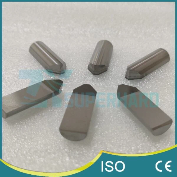
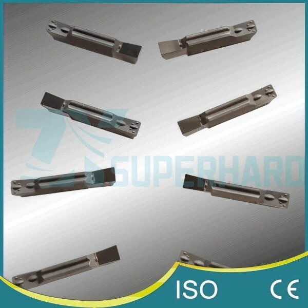
PCD Notching and Grooving Tools for Ribs and Profiles
These are perhaps some of the most specialized PCD tools used in roll machining. “Notching” or “grooving” means cutting specific shapes, channels, or patterns onto the roll surface. These aren’t just simple cylinders; the features created are often critical to the roll’s function.
What do these tools look like?
- They might be inserts with a specific profile ground onto the PCD edge.
- They can also be solid tools, where a PCD tip with the required shape is brazed (like soldering with strong metal) onto a carbide shank or body for support. (Example: PCD/CVD Notching Tools5)
What are they used for?
- Creating ribs on rolls used in steel mills to form patterns on products like rebar (reinforcing bars). The shape of the groove in the tool directly creates the rib shape on the steel.
- Machining precise grooves for seals or fluid channels.
- Texturing rolls used in paper or plastic film production.
- Engraving or marking identification codes or logos directly onto the roll.
Because the required profiles are often unique to a specific product or process, these PCD notching and grooving tools frequently need to be custom-designed based on the exact requirements of the roll. Their precision is key to the quality of the final product made by the roll.
PCD Milling Cutters for Shaping and Contouring Rolls
While turning shapes the main round body, milling uses a rotating cutter to create other kinds of shapes on a roll. Imagine using a router instead of a lathe. PCD milling cutters bring the benefits of diamond hardness to these operations.
Types include:
- Face Mills: Larger diameter cutters, often using multiple PCD inserts, designed to machine large flat surfaces quickly. They might be used on the ends of rolls.
- End Mills: Smaller diameter, shanked tools used for creating slots, pockets, or complex contours on the roll surface or ends.
While perhaps less common than turning or grooving for the primary roll surface, PCD milling cutters are valuable for:
- Machining complex profiles or non-cylindrical features on certain roll types.
- Creating large chamfers or flats.
- Facing operations on roll ends to ensure they are perfectly flat and perpendicular.
Using PCD allows these milling operations to be performed efficiently, especially on abrasive or hard roll materials, maintaining accuracy and good surface finish.
PCD Drills and Reamers for Precision Holemaking
Sometimes, rolls need precisely located and sized holes. These might be for:
- Internal heating or cooling channels to control the roll’s temperature.
- Mounting points for attaching the roll to machinery.
- Access for sensors or other components.
PCD comes into play here too:
- PCD Drills: Used to create the initial hole. They typically have PCD tips brazed onto a strong carbide body, providing the hardness needed to drill through tough roll materials efficiently.
- PCD Reamers: Used after drilling to slightly enlarge the hole to a very exact diameter and improve its surface finish and roundness. Like PCD drills, they use PCD cutting edges for wear resistance and precision.
Using PCD for drilling and reaming ensures that holes in hard or abrasive rolls can be produced accurately and with long tool life, contributing to the overall quality and functionality of the roll.
Overview of Specialized and Custom PCD Tooling Options
Beyond the main categories above, the world of PCD tooling includes even more specialized options relevant to roll machining.
- PCD Engraving Tools: These are often designed for very fine detail work, like engraving small text, logos, or intricate patterns onto roll surfaces, demanding extreme sharpness and precision.
- Custom Form Tools: Sometimes, a single PCD tool can be designed with a unique, complex profile to machine multiple features on the roll simultaneously, increasing efficiency.
A key takeaway is that customization is very common in PCD tooling for rolls. Because rolls often have unique designs and process demanding materials, standard off-the-shelf tools might not be sufficient. Manufacturers often work closely with specialized PCD tool suppliers to design and produce tools tailored exactly to their specific roll material, profile requirements, and machining conditions. This collaborative approach ensures the tooling delivers optimal performance and meets the stringent quality demands of modern roll applications.

Matching PCD Tools to Specific Roll Materials and Machining Tasks
Matching PCD tools effectively involves analyzing the roll material’s properties (like hardness and abrasiveness), selecting an appropriate PCD grade offering the right balance of wear resistance and toughness, choosing the correct tool geometry for the required cut, aligning the tool type to the specific operation (e.g., roughing vs. finishing), and considering the influence of coolant.
Assessing Roll Material Characteristics (TC, HSS, Cast Iron, etc.)
The very first step in choosing the right PCD tool is to deeply understand the material your roll is made from. Why? Because the roll material dictates how the tool will perform and wear. Key things to know include:
- Hardness: This is a critical factor. Is it an extremely hard Tungsten Carbide (TC) roll (often above HRA 88), a High-Speed Steel (HSS) roll (perhaps HRC 60-67), or a type of Cast Iron (like chilled iron, maybe HRC 55-65)? Harder materials generally demand the superior wear resistance of PCD. Knowing the specific hardness value (e.g., HRC or HRA) helps narrow down PCD grade choices.
- Abrasiveness: Some materials aren’t necessarily the hardest, but they contain hard particles that act like sandpaper on the cutting tool. Tungsten Carbide, with its hard carbide grains, and certain alloyed cast irons are highly abrasive. PCD excels in resisting this abrasive wear.
- Toughness: Is the material prone to chipping (brittle) or does it deform more before breaking (tough)? This influences how aggressively you can cut and what kind of tool edge preparation is needed.
- Chemical Makeup: As mentioned earlier, knowing if the material is ferrous (iron-based) or non-ferrous helps decide between PCD and CBN, especially considering cutting temperatures.
Always start with the most accurate information you can get about the roll material you intend to machine. This forms the foundation for all subsequent tooling decisions.
Selecting the Appropriate PCD Grade for Material Hardness
PCD isn’t just one single material; tool manufacturers offer different “grades.” The main difference between grades is usually the size of the diamond particles fused together. Think of it like sandpaper having different grits for different jobs.
Here’s a simple breakdown:
| PCD Grade Type | Typical Diamond Size (Microns, µm) | Key Characteristic | Best Suited For (Roll Machining Examples) |
|---|---|---|---|
| Fine | ~ 1-5 µm | Best edge toughness & finish | Finishing cuts demanding smoothness, handling interruptions |
| Medium | ~ 10-25 µm | Good balance (common) | General purpose TC machining, finishing hard ferrous rolls |
| Coarse | ~ 30+ µm | Best abrasion resistance | Roughing highly abrasive materials (e.g., high-content TC) |
- Fine Grades: Smaller diamond grains create a sharper, more chip-resistant edge. These are often chosen for finishing operations where achieving the best possible surface smoothness is the goal, or for cuts that might involve interruptions (like keyway slots) where edge chipping is a concern.
- Medium Grades: Offer a good compromise between wear resistance and edge strength. They are widely used for many roll machining applications, including general turning and grooving of TC rolls.
- Coarse Grades: Larger diamond particles provide the highest resistance to abrasive wear. These grades are often selected for roughing operations or when machining extremely abrasive roll materials, where maximizing the tool’s lifespan is the primary objective. The edge might be slightly less keen than finer grades.
The key principle is a trade-off: Finer grades generally give better edge toughness and finish, while coarser grades offer better resistance to abrasive wear. It’s important to note that PCD grades and their specific properties (like grain size distribution and binder content) can vary significantly between manufacturers. Always consult your tool supplier’s recommendations for matching their specific grades to your roll material and operation for the best results.
Choosing Correct Tool Geometry (Edge Prep, Angles)
Once you have an idea of the right PCD grade, the actual shape or geometry of the cutting edge is equally critical. This includes several factors:
- Edge Preparation: PCD is hard but can be brittle at the very edge. To prevent tiny chips from breaking off (micro-chipping), manufacturers often apply an edge preparation:
- Hone: A very small radius applied to the edge.
- Chamfer (or T-land): A small flat angle ground onto the edge.
The type and size of the edge prep depend on the task. Roughing or interrupted cuts typically need a heavier preparation for more strength, while finishing cuts might use a lighter hone or even a sharp edge for the best surface quality.
- Rake Angle: This is the angle of the cutting face relative to the workpiece. It influences cutting forces, heat generation, and how chips flow away from the cut.
- Clearance Angle: This is the angle providing space behind the cutting edge so the tool doesn’t rub excessively on the freshly cut surface.
- Nose Radius (for inserts): The radius at the corner of an insert affects the surface finish and the strength of the tool tip. A larger radius is generally stronger but can increase cutting forces, while a smaller radius might allow for finer details but be less robust.
Think of it like sharpening a kitchen knife – you might use a different angle and edge finish depending on whether you’re chopping tough vegetables or finely slicing delicate fish. Getting the geometry right requires balancing edge strength, cutting forces, chip control, and the desired surface finish. This is often best determined through experience or close consultation with your tooling provider.
Aligning Tool Type with the Specific Machining Operation (Roughing, Finishing, Notching)
This might seem obvious, but it’s crucial: use the right category of tool for the job at hand. You wouldn’t use a delicate engraving tool for heavy material removal.
- Roughing: The goal is to remove a lot of material quickly, not necessarily achieve the final perfect surface. This requires robust tools – perhaps thicker PCD inserts, tools with coarser PCD grades, and stronger edge preparations.
- Finishing: The focus shifts to achieving the final precise dimensions and excellent surface quality. This usually involves lighter cuts using tools with sharper edges, often finer PCD grades, and geometries designed for smooth cutting.
- Notching/Grooving/Profiling: This requires specialized tools (as described in the previous section) that have the exact profile needed for the feature being machined. Precision and edge retention are critical. Often uses specialized tools or inserts. Edge strength is vital if it’s an interrupted cut.
- Drilling/Reaming: Dedicated PCD drills and reamers must be used for holemaking.
First, choose the appropriate tool type (insert, notcher, end mill, drill). Then, refine the selection of PCD grade and geometry based on whether the specific operation within that type is roughing, finishing, or involves unique challenges like interruptions.
Considering the Impact of Coolant and Lubrication
Finally, how you plan to cool or lubricate the cutting zone can influence tool selection, although PCD’s high thermal conductivity makes it more tolerant of heat than other materials.
Considerations include:
- Chip Flushing: Especially in deep grooves or bores, a good flow of coolant is essential to wash chips away, preventing them from jamming and potentially damaging the tool edge or the roll surface. Some tools might have internal coolant channels designed for this.
- Thermal Stability: While PCD handles heat well, consistent cooling helps maintain the dimensional accuracy of the roll during machining by preventing excessive thermal expansion. It can also minimize thermal shock to the PCD tool itself.
- Lubrication: Reducing friction at the cutting edge can sometimes improve surface finish and may slightly reduce cutting forces.
When selecting your PCD tool, ensure it’s compatible with your planned coolant strategy (flood coolant, Minimum Quantity Lubrication – MQL, or even dry machining, though less common for demanding roll applications). The need for effective chip evacuation, in particular, might influence the choice of tool holder or tool design.
Critical Performance Factors and Best Practices for Using PCD Tools on Rolls
Achieving optimal performance with PCD tools in roll machining relies on using the correct cutting parameters (speeds, feeds, depth of cut), ensuring the machine tool is rigid and stable, employing proper tool handling and secure clamping, carefully monitoring tool wear, and applying specific strategies for challenges like interrupted cuts.
Optimizing Cutting Parameters (Speeds, Feeds, Depth of Cut)
Getting the “recipe” right for how you cut is fundamental. The main ingredients in this recipe are the cutting parameters:
- Cutting Speed: How fast the surface of the roll moves past the cutting tool. Usually measured in surface feet per minute (SFM) or meters per minute (m/min). PCD generally allows for much higher cutting speeds than carbide.
- Feed Rate: How quickly the tool advances along or into the roll. Measured per revolution (like inches per revolution – IPR or mm/rev) or sometimes per cutting edge (per tooth).
- Depth of Cut (DOC): How much material the tool removes in a single pass.
While PCD tools can often run very fast, the “best” parameters aren’t always the absolute maximum possible. The ideal settings depend on a balance of factors: the specific PCD grade and geometry you chose, the exact roll material and its hardness, the power and stability of your machine tool, and the surface finish you need to achieve. For example, finishing passes usually require lighter depths of cut and potentially adjusted feed rates compared to roughing passes.
How to approach optimization? Start with the recommendations provided by the PCD tool manufacturer – these are developed based on extensive testing and provide a safe and effective starting point. Then, carefully observe the results: Is the surface finish good? Are the chips forming correctly? Is there any unusual noise or vibration? You can then make small, controlled adjustments to one parameter at a time (e.g., slightly increase speed, then evaluate; slightly adjust feed, then evaluate) to find the sweet spot for your specific situation. Remember, cutting parameters are highly specific to the combination of PCD tool, roll material, machine, and operation. Always use the tool manufacturer’s recommendations as a starting point and adjust carefully based on observed performance, as the optimal range can vary significantly.
The Importance of Machine Tool Rigidity and Stability
Imagine trying to perform delicate surgery on a shaky table – it wouldn’t work well! Similarly, PCD tools need a very stable environment to perform their best. Machine tool rigidity means how well the machine resists bending or vibrating under the forces of cutting.
Why is this so critical for PCD?
- Preventing Chipping: PCD is extremely hard, but it can also be brittle. Vibrations (often called “chatter”) from the machine, the roll itself, or the tool holder can act like tiny hammer blows on the delicate cutting edge, causing it to chip or even fracture prematurely.
- Maintaining Accuracy: A stiff, stable machine holds the roll and the cutting tool precisely where they need to be. Any flexing or movement in the system during the cut will lead to errors in the roll’s dimensions or a poor surface finish.
Key elements for good rigidity include:
- A heavy, well-maintained machine tool foundation and structure.
- Securely clamping the roll so it cannot move or vibrate.
- Using high-quality tool holders that grip the PCD tool tightly and run true (without wobble).
- Keeping the tool overhang (how far the tool sticks out from the holder) as short as possible.
Always use the most rigid and well-maintained machine available for machining rolls with PCD tools. Ensuring stability is paramount to protecting the tool and achieving the desired quality.
Proper Tool Handling, Setup, and Clamping Techniques
Sometimes, a PCD tool can fail before it even starts cutting due to improper handling or setup. Remember these points:
- Handle with Care: PCD cutting edges are strong in the cut but can be easily damaged if dropped or knocked against hard surfaces. Keep tools in their protective cases until you are ready to mount them. Treat them like precision instruments.
- Cleanliness is Key: Before mounting a PCD insert into a holder or a PCD tool into the machine spindle, make absolutely sure the seating surfaces (pockets, tapers, flanges) are perfectly clean. Even tiny bits of dirt or old chips can cause the tool to sit incorrectly, leading to vibration, poor performance, or even tool breakage.
- Secure Clamping: If using inserts, use a torque wrench to tighten clamping screws to the manufacturer’s recommended specification. Over-tightening can stress or crack the insert or holder; under-tightening allows the insert to move, causing vibration and likely failure. Ensure clamps are applying even pressure. For shanked tools (like drills or end mills), use high-quality, high-pressure chucks (like hydraulic or shrink-fit holders if possible) to ensure a secure grip and minimize runout (wobble).
Taking a few extra moments during handling and setup can save significant time and money by preventing easily avoidable tool failures.
Monitoring Tool Wear and Identifying End-of-Life
Even though PCD tools last a long time, they don’t last forever. Knowing when to change a tool is important to maintain quality and avoid damaging the roll or the machine. How can you tell when a PCD tool is nearing the end of its useful life?
- Look Closely: Regular visual inspection with magnification (a small handheld microscope or loupe is very helpful) is crucial. Look for signs of tool wear6 on the cutting edge:
- Flank Wear: Rubbing wear on the side of the tool below the cutting edge.
- Chipping: Small pieces broken away from the cutting edge.
- Cratering: Wear on the top face of the tool where the chip flows over it.
- Check the Surface Finish: Often, one of the first signs of a dulling tool is a noticeable decline in the surface finish quality on the roll.
- Listen and Feel: Changes in the sound of the cut or increased vibration can indicate a worn tool.
- Monitor Dimensions: If the size of the roll starts to drift away from the target dimension, it’s a strong sign the tool edge has worn down.
- Watch Machine Load: An increase in the power needed to make the cut can signal that the tool is becoming dull and working harder.
It’s best practice to establish clear wear criteria (e.g., maximum allowable flank wear land width, specific number of parts, or surface finish threshold) and change the tool before it fails completely. Running a tool until it breaks catastrophically risks damaging the expensive roll or the tool holder. Consistent monitoring allows for predictable, planned tool changes.
Strategies for Handling Challenges like Interrupted Cuts
An “interrupted cut” happens when the cutting edge repeatedly enters and leaves the roll material during a single pass. Examples include machining across existing grooves, keyways, flats, or holes on the roll surface. These situations are particularly tough on cutting tools, especially brittle materials like PCD.
Why are interruptions challenging?
- Impact: Each time the edge re-enters the material, it experiences a small impact force.
- Thermal Fluctuation: The edge heats up rapidly in the cut and cools quickly in the air, causing stress.
Here are strategies to improve success in interrupted cuts with PCD:
- Use Tougher Grades: Select finer-grained PCD grades known for better edge toughness and chip resistance (refer back to H3 on grade selection).
- Employ Stronger Edge Preps: Use a more robust edge preparation (a larger hone or chamfer) to reinforce the cutting edge against impact.
- Adjust Parameters: It’s often necessary to reduce the cutting speed and/or feed rate during interrupted sections to lessen the impact force on the edge.
- Optimize Tool Path (if possible): Advanced CAM software might allow programming the tool path to “roll” into the cut smoothly rather than hitting it abruptly.
- Maximize Rigidity: Ensure the machine setup is as rigid as possible to absorb impact forces without excessive vibration.
Successfully machining interrupted features with PCD often involves accepting slightly more conservative parameters compared to continuous cutting, prioritizing tool reliability over maximum speed. Careful planning and tool selection are essential.
Conclusion
Choosing and using the right PCD tools for roll machining involves careful consideration of the material, the specific task, and best practices in application. By understanding the benefits, selecting the appropriate tool type and grade, matching it to the job, and optimizing its use, manufacturers can significantly enhance performance, quality, and efficiency in their roll machining operations.
References
- Sintering1 – ScienceDirect topic page explaining the sintering process used to create materials like PCD from powders.
- Total Cost of Ownership (TCO)2 – ZYDiamondTools guide explaining the TCO concept and application for superhard tooling & abrasives.
- PCD3 – ZYDiamondTools blog post providing a comprehensive overview of Polycrystalline Diamond (PCD) tools.
- CBN (Cubic Boron Nitride)4 – ZYDiamondTools detailed guide to CBN cutting tools, a common alternative to PCD.
- PCD/CVD Notching Tools5 – ZYDiamondTools product page example for PCD/CVD notching tools used in roll machining.
- Tool Wear6 – ScienceDirect topic page providing an overview of tool wear mechanisms in engineering.


