-
Whatsapp: +86 13526572721
-
Email: info@zydiamondtools.com
-
Address: AUX Industrial Park, Zhengzhou City, Henan Province, China
-
Whatsapp: +86 13526572721
-
Email: info@zydiamondtools.com
-
Address: AUX Industrial Park, Zhengzhou City, Henan Province, China

How Do You Choose and Apply the Right PCD Grooving Tools for Optimal Results?

Getting the best results with PCD grooving tools can seem challenging, so what key areas do you need to focus on?
Achieving optimal results with PCD grooving tools requires focusing on four key areas: correctly selecting the tool based on material, geometry, and machine factors; optimizing performance through proper cutting parameters and coolant application; carefully evaluating potential suppliers based on technical and service criteria; and understanding the distinct advantages PCD offers over other materials for specific grooving applications.
What Key Factors Determine the Correct PCD Grooving Tool Selection?
So, with all the options out there, how do you actually choose the perfect PCD grooving tool for your specific job?
Selecting the right Polycrystalline Diamond (PCD)1 grooving tool involves carefully matching the PCD grade to the workpiece material you are cutting, understanding and specifying the correct tool geometry including groove dimensions and edge preparation, deciding between readily available standard tools and custom-designed specials, and finally, considering the rigidity and condition of your machine tool setup.
Let’s break down these key factors one by one. Getting these right is essential for achieving accurate grooves, long tool life, and efficient production.
Matching PCD Grade to Workpiece Material
Choosing the right PCD grade is perhaps the most critical first step. Think of PCD like different types of sandpaper – some are fine for a smooth finish, while others are coarse and tough for rougher jobs. PCD grades mainly differ in their diamond grain size and the binder material holding the diamond particles together. Using the wrong grade can lead to rapid tool wear or poor surface finish.
Non-Ferrous Metals (Aluminum Alloys, Copper, Brass)
For softer, non-ferrous metals like common aluminum alloys (e.g., 6061 used in many structural parts), copper, or brass, you generally want a PCD grade with a finer diamond grain size (e.g., 2-10 µm). Why? Finer grains allow for sharper cutting edges, which helps produce a smoother, cleaner surface finish on the groove walls and bottom. This is crucial for parts like hydraulic valve bodies or components requiring tight seals. These grades typically offer excellent wear resistance in these less abrasive materials.
Composites (CFRP, GFRP)
Carbon Fiber Reinforced Polymers (CFRP)2 and Glass Fiber Reinforced Polymers (GFRP) are common in aerospace and automotive applications but are very abrasive. For these materials, a medium to coarse diamond grain size (e.g., 10-25 µm or even larger) is often preferred. The larger, tougher diamond grains offer better resistance to the abrasive wear caused by the hard carbon or glass fibers. A balance must be struck; too coarse a grain might increase cutting forces or slightly reduce finish quality, but tool life is often the primary concern here.
Highly Abrasive Materials (High-Silicon Aluminum, Ceramics, Wood Composites)
Materials like high-silicon aluminum (common in engine blocks, pistons), metal matrix composites (MMCs), pre-sintered ceramics, or even some dense wood composites are extremely abrasive or tough. These demand PCD grades with coarse diamond grains (often 25 µm and above) and sometimes specialized binder materials for maximum toughness and abrasion resistance. Selecting the wrong grade here can lead to catastrophic tool failure very quickly.
- Important Note: PCD manufacturers often have their own proprietary grade designations and specific recommendations. The grain sizes mentioned are general guidelines. Always consult your tool supplier to confirm the best PCD grade for your specific material and application. They have detailed data based on extensive testing.
Understanding Grooving Tool Geometry
Once you have a suitable PCD grade in mind, the next step is defining the tool’s shape and size – its geometry. This needs to precisely match the groove you intend to create.
Groove Width and Depth Requirements
This is fundamental. The PCD insert must be designed to cut the exact groove width specified in the engineering drawing, within the required tolerances. Similarly, the tool body and insert combination must allow for machining to the correct groove depth without interference. For deep grooves, chip evacuation becomes critical, influencing other geometric features.
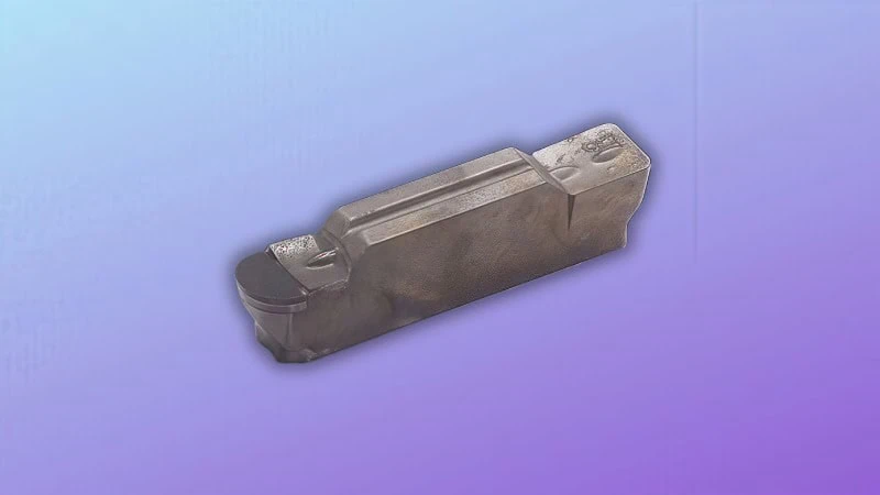
Insert Shape and Edge Preparation
PCD grooving inserts come in various shapes. Some follow standard ISO styles, while others might be proprietary. The shape influences how the insert is held and its overall strength. More importantly, the edge preparation significantly impacts performance.
- Sharp Edge: Offers lower cutting forces and potentially better finish on soft materials but is more fragile.
- Honed Edge: A slight rounding of the cutting edge (e.g., 0.01-0.03 mm radius) adds strength and prevents chipping in harder materials or interrupted cuts, though it slightly increases cutting forces.
- Chamfered Edge: A small flat angle on the edge provides maximum strength for heavy or unstable cutting conditions but increases cutting forces more significantly.
The choice depends on the material, the operation’s stability, and whether finish or tool life is the priority. Again, specific edge preparations can vary between suppliers, so verify details when ordering.
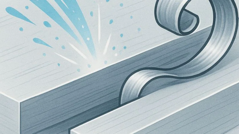
Chipbreaker Design Considerations
Grooving often produces long, stringy chips that can wrap around the tool or workpiece, potentially damaging the tool or surface finish. A chipbreaker is a feature (often a molded or ground shape) on the insert’s top surface designed to curl and break the chip into smaller, more manageable pieces. Effective chip control is crucial, especially in deeper grooves or automated processes. Chipbreaker designs vary widely based on the material being cut and the feed rates used. Some PCD tools for non-ferrous materials may not require aggressive chipbreakers, while others for materials producing tougher chips benefit greatly.
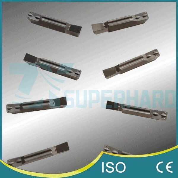
Standard vs. Special Custom Tools
You’ll also need to decide whether a standard, off-the-shelf tool will work or if you need a custom-designed solution.
When Standard Inserts Suffice
If your groove has common dimensions (width, depth, simple profile) and standard tolerances, a standard PCD grooving insert3 is often the most cost-effective and readily available option. Many manufacturers offer catalogs of standard sizes and shapes. This is ideal for general-purpose grooving.
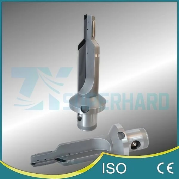
Identifying the Need for Custom Solutions
When do you need to go custom? Consider these situations:
- Non-standard groove profile: The groove requires specific radii, angles, or complex shapes (e.g., O-ring grooves, seal grooves, multi-step grooves).
- Extremely tight tolerances: Tolerances beyond what standard tooling can reliably achieve.
- Combined operations: A special tool designed to perform grooving plus another feature like chamfering or turning in a single pass to save cycle time.
- Unique material challenges: Requiring a specific combination of PCD grade and geometry not available as standard.
Custom tools typically have a higher initial cost and longer lead times but can provide significant value by meeting exact specifications or improving efficiency in high-volume production.
Considering Machine Tool and Setup Rigidity
Finally, don’t overlook your machining environment. PCD is very hard but also more brittle than materials like carbide. It doesn’t tolerate vibration well.
- Why Rigidity Matters: A machine tool with worn bearings, a weak spindle, or loose components can cause vibrations during cutting. Likewise, a flimsy tool holder or poor workpiece clamping allows movement.
- Impact of Vibration: Vibration leads to inconsistent cutting, poor surface finish in the groove, dimensional inaccuracies, and, critically, potential chipping or premature failure of the brittle PCD cutting edge. Think of trying to write neatly on a shaky table – the result won’t be good.
- What to Check: Ensure your machine tool is well-maintained. Use high-quality, rigid tool holders (e.g., hydraulic chucks, shrink-fit holders often provide better rigidity and runout accuracy than standard collet chucks for demanding PCD applications). Ensure your workpiece is securely clamped as close to the machining area as possible. A stable setup is key to unlocking the full potential of PCD grooving tools.
How Can You Optimize PCD Grooving Performance and Tool Life?
Alright, you’ve carefully selected your PCD grooving tool. So, how do you ensure you get the absolute best performance out of it and make it last as long as possible?
Optimizing PCD grooving involves using the correct cutting parameters (speed, feed, depth of cut) tailored to your material and tool, applying coolant effectively to manage heat and chips, and knowing how to recognize and troubleshoot common machining issues like tool wear or poor surface finish.
Getting these aspects right is crucial for maximizing productivity, achieving consistent quality, and getting the full economic benefit from your investment in advanced PCD tooling. Let’s dive into the details.
Recommended Cutting Parameters
Using the right cutting parameters – speed, feed, and depth of cut – is fundamental to success with any cutting tool, and especially important for PCD due to its unique properties. Think of these parameters like adjusting the settings on a high-performance machine; small changes can have a big impact.
Cutting Speed (Vc) Guidelines
Cutting speed (Vc) refers to how fast the cutting edge moves across the workpiece surface, usually measured in meters per minute (m/min) or surface feet per minute (SFM). PCD tools generally thrive at much higher cutting speeds compared to carbide, especially in non-ferrous materials. This is one of their main advantages, allowing for significantly reduced cycle times.
- For Aluminum Alloys: Speeds can often range from 500 m/min up to 1500 m/min or even higher in ideal conditions. For example, finishing grooves in an aluminum transmission casing might run effectively at 1000 m/min.
- For Composites & Abrasive Materials: Speeds are typically lower due to the high abrasion, perhaps in the range of 50-300 m/min. Machining grooves in a high-silicon aluminum engine block might require staying towards the lower end of this range to manage wear.
Crucial Reminder: These are just general starting points! The optimal cutting speed depends heavily on the specific PCD grade, the exact workpiece material, the machine’s capability, and the overall rigidity of the setup. Always consult your tooling supplier for their recommended starting parameters for your specific tool and application, and be prepared to fine-tune based on results.
Feed Rate (fz / fn) Considerations
Feed rate determines how fast the tool advances into the material per revolution (fn, in mm/rev or inch/rev) or per tooth (fz, in mm/tooth or inch/tooth for milling, but fn is more common for grooving/turning). Feed rate directly influences:
- Chip Thickness: Affects cutting forces and heat generation.
- Surface Finish: Generally, lower feeds produce smoother finishes, but too low can cause rubbing instead of cutting.
- Tool Life: An optimal feed rate balances productivity with wear. Too high a feed can chip or break the PCD edge; too low can cause rubbing and accelerated flank wear.
Finding the right feed rate is a balancing act. For instance, a typical starting point for grooving aluminum might be 0.05 – 0.15 mm/rev, but this needs adjustment based on the groove width, depth, and material behavior. Again, use supplier recommendations as a starting point and adjust based on chip formation, surface finish, and tool wear.
Depth of Cut (ap) Strategies
Depth of cut (ap) is how much material the tool removes in the axial direction (depth into the groove) in a single pass.
- Shallow Grooves: Often machined in a single pass if the machine power and rigidity allow.
- Deep Grooves: May require multiple passes at reduced depths. Taking too large a depth of cut can lead to excessive cutting forces, vibration, poor chip evacuation, and potential tool failure. For example, a 10mm deep groove might be machined in 2-3 passes rather than attempting it all at once.
The strategy depends on the groove depth-to-width ratio, material, machine capability, and rigidity. Ensure the depth of cut doesn’t overload the tool or the machine.
The Role of Coolant Application
Coolant (or cutting fluid) plays several vital roles in PCD grooving:
- Cooling: Reduces heat at the cutting edge, preserving the PCD structure and preventing workpiece thermal damage.
- Lubrication: Reduces friction between the tool, chip, and workpiece.
- Chip Evacuation: Flushes chips away from the cutting zone, preventing them from damaging the surface or tool.
Effective coolant application is critical.
Flood Coolant vs. MQL (Minimum Quantity Lubrication)
- Flood Coolant: The traditional method, using a high volume of water-soluble oil or synthetic fluid. It generally provides excellent cooling and chip flushing. This is often preferred for tougher materials or deep grooving where chip evacuation is challenging.
- MQL (Minimum Quantity Lubrication): Uses a very small amount of oil mixed with compressed air, delivered as a mist or aerosol directly to the cutting zone. It’s more environmentally friendly, reduces fluid costs, and can minimize thermal shock to the cutting edge. MQL is increasingly popular, especially for high-speed machining of aluminum where effective chip evacuation can still be achieved.
The best choice depends on the material, operation, machine capabilities, and shop environmental policies.
Optimizing Coolant Pressure and Direction
Simply having coolant present isn’t enough; it needs to get where it matters – right at the cutting edge inside the groove.
- Pressure: Higher coolant pressure (e.g., through-tool coolant or high-pressure external nozzles) can be very effective at penetrating deep grooves, breaking chips, and preventing chip packing.
- Direction: Nozzles must be aimed precisely at the cutting zone. Poor aiming means the coolant might not reach the edge effectively, leading to overheating and premature wear. Imagine trying to put out a small fire by spraying water next to it – it doesn’t work!
Experiment with nozzle placement and consider high-pressure coolant options for difficult grooving tasks.
Recognizing and Troubleshooting Common Issues
Even with careful selection and setup, you might encounter issues. Knowing how to spot and fix them is key to optimization.
Addressing Premature Edge Wear
Is your tool wearing out faster than expected? Look for these potential causes:
- Incorrect Cutting Parameters: Speed too high/low, or feed too high/low.
- Wrong PCD Grade: Grade not suitable for the material’s abrasiveness.
- Ineffective Coolant: Not reaching the edge, wrong type, or insufficient volume/pressure.
- Vibration/Lack of Rigidity: Setup is unstable (check machine, holders, clamping).
- Solution: Review and adjust cutting parameters (often start by reducing speed slightly). Confirm PCD grade suitability with supplier. Optimize coolant delivery. Improve setup rigidity.
Improving Groove Surface Finish
Is the finish on the groove walls or bottom rough or inconsistent? Consider these factors:
- Incorrect Feed Rate: Feed too high leaves prominent tool marks. Feed too low might cause rubbing or built-up edge (BUE).
- Worn Cutting Edge: A dull or chipped edge cannot produce a clean cut.
- Built-Up Edge (BUE): Common in aluminum; material welds temporarily to the cutting edge, then breaks off, leaving a rough surface. Often caused by too low cutting speed or ineffective coolant.
- Vibration: Causes chatter marks on the surface.
- Solution: Optimize feed rate (often slightly lower for finish passes). Check tool for wear/damage. Increase cutting speed (within limits) or improve coolant lubrication to reduce BUE. Address any sources of vibration. Ensure the edge preparation is appropriate (sometimes a sharper edge helps finish in soft materials if stability allows).
Managing Chip Control Problems
Are chips long and stringy, wrapping around the tool or workpiece?
- Incorrect Parameters: Feed rate or depth of cut may not be suitable for the chipbreaker design.
- Ineffective Chipbreaker: The chipbreaker geometry might not be right for the material or cutting conditions.
- Poor Coolant Application: Insufficient pressure or flow to break and flush chips effectively.
- Solution: Adjust feed rate and/or depth of cut (sometimes increasing feed slightly can help break chips). Consider a tool with a different chipbreaker geometry if the problem persists. Optimize coolant delivery, potentially increasing pressure.
Key Criteria for Evaluating PCD Grooving Tool Suppliers
Choosing the right PCD grooving tool is half the battle; finding the right supplier to provide it is just as important. So, what should you actually look for when evaluating potential suppliers for these specialized tools?
Evaluating a potential PCD grooving tool supplier involves assessing their technical expertise and application support, verifying their manufacturing precision and commitment to quality consistency, understanding their capability to produce non-standard or custom tools if needed, gauging their lead time reliability and stock availability, and finally, considering their overall responsiveness and communication effectiveness.
Partnering with the right supplier ensures you not only get high-quality tools but also the support needed to use them effectively and reliably integrate them into your production. Let’s examine these criteria more closely.
Technical Expertise & Application Support
PCD tooling is more complex than standard tooling. Therefore, a supplier’s technical knowledge is crucial. You aren’t just buying a part; you are often buying a performance solution.
- Deep Knowledge: Does the supplier demonstrate a thorough understanding of PCD materials science? Do they understand how different grades perform in various workpiece materials specific to grooving? Can they explain why a particular grade or geometry is recommended?
- Application Help: Look for suppliers who offer meaningful application support. This includes providing realistic starting parameters for speed, feed, and depth of cut. Furthermore, they should be capable of helping you troubleshoot issues like unexpected tool wear or poor surface finish. Think of it like this: you want a partner who can help you fine-tune the tool’s performance in your specific environment.
Manufacturing Precision & Quality Consistency
The performance of a PCD tool relies heavily on how precisely it’s made and how consistent that quality is from one tool to the next.
- Tight Tolerances: High-performance grooving often requires tight tolerances on the groove width, depth, and profile. Assess the supplier’s demonstrated ability to manufacture tools that consistently meet these precise geometric requirements.
- Quality Systems: While specific certifications aren’t everything, inquire about their quality control processes. How do they ensure the PCD edge quality is consistent? What checks are in place during manufacturing to maintain geometric accuracy and material integrity? Consistent quality means predictable performance and tool life in your machines. You need assurance that the 100th tool will perform just like the first one.
Capability for Non-Standard & Custom Tools
As discussed earlier, sometimes a standard, off-the-shelf grooving tool isn’t sufficient. Your application might require a unique groove profile, a special tolerance, or a combined cutting function.
- Design Resources: Does the supplier have the engineering capability to design custom tools based on your specific requirements or part drawings?
- Manufacturing Flexibility: Can their production processes accommodate special requests efficiently?
- Collaborative Process: How do they work with customers on custom designs? Look for a collaborative approach where they discuss the application, suggest design improvements, and provide clear drawings for approval before manufacturing.
Even if you primarily use standard tools now, knowing a supplier has strong custom capabilities provides flexibility for future needs or challenging projects.
Lead Time Reliability & Stock Availability
Predictable delivery is essential for keeping production lines running smoothly. Unreliable lead times can cause significant disruptions.
- Transparency: Does the supplier provide clear and realistic lead times for both standard and custom tools?
- On-Time Delivery: Do they have a track record of meeting their promised delivery dates? While occasional delays can happen, consistent lateness is a red flag.
- Stock Levels: For standard items you use regularly, does the supplier maintain adequate stock levels to ensure quick shipment? Or what is their typical manufacturing time if items are not stocked?
Keep in Mind: Lead times, especially for custom tools, can naturally vary significantly based on complexity and current workload. It’s always wise to confirm estimated lead times clearly during the quoting and ordering process.
Supplier Responsiveness & Communication
Effective communication and quick responses are vital, especially when technical questions arise or issues need resolving quickly.
- Ease of Contact: How easy is it to get in touch with knowledgeable sales or technical staff?
- Clarity and Speed: Do they respond to inquiries promptly and provide clear, understandable answers? Waiting days for a simple answer can be frustrating and costly.
- Problem Resolution: How do they handle issues if they arise (e.g., a tool not performing as expected)? Look for a supplier who is proactive and helpful in finding solutions. Good communication builds a strong working relationship.
Why Choose PCD Over Other Materials for Grooving Applications?
So, we’ve explored how to select and optimize PCD grooving tools, but you might still wonder: why choose PCD when other, often less expensive, materials like cemented carbide4 are available?
Choosing Polycrystalline Diamond (PCD) for grooving applications, especially in non-ferrous metals and abrasive materials, offers significant advantages including vastly superior wear resistance leading to much longer tool life, the ability to run at significantly higher cutting speeds for increased productivity, often resulting in better surface finishes on target materials, and ultimately delivering lower total costs per part in high-volume production despite a higher initial tool price.
While carbide tools certainly have their place, PCD truly shines in specific situations, making it the preferred choice for many demanding grooving operations. Let’s look at these benefits more closely.
Achieving Superior Wear Resistance and Extended Tool Life
This is perhaps the most well-known benefit of PCD. Diamond is the hardest known material, and PCD harnesses this hardness. When grooving materials like aluminum alloys (especially those with high silicon content), copper, brass, composites (like CFRP), or ceramics, PCD tools resist abrasive wear far better than compared to carbide tools5.
- How much better? While it varies greatly depending on the specific material and cutting conditions, it’s not uncommon for PCD grooving tools to last 10 times, 50 times, or even over 100 times longer than comparable carbide tools in the right application. Imagine grooving thousands of high-silicon aluminum pistons with a single PCD tool, compared to changing carbide inserts multiple times per shift.
- The Impact: This drastically extended tool life means significantly fewer tool changes, leading to reduced machine downtime, lower tooling inventory needs, and more consistent part quality over long production runs.
Enabling Higher Cutting Speeds and Productivity
Because PCD handles heat well and resists wear so effectively, it allows for much higher cutting speeds (Vc) compared to carbide, particularly in non-ferrous materials.
- Speed Advantage: As mentioned earlier, while carbide might groove aluminum at speeds of 150-400 m/min, PCD can often run efficiently at 500-1500 m/min or more.
- Productivity Boost: Higher cutting speeds directly translate to shorter cycle times for each groove machined. If the grooving operation is a significant part of the overall cycle time for a part, using PCD can dramatically increase the number of parts produced per hour or per shift. This boosts overall machine tool utilization and factory output, directly impacting profitability. For example, cutting a complex groove pattern in an aluminum automotive wheel might take 25 seconds with carbide but only 8 seconds with PCD, a significant saving multiplied over thousands of parts.
Obtaining Improved Surface Finish on Target Materials
PCD often delivers a superior surface finish on the materials it’s designed for, especially aluminum alloys and composites.
- Why? PCD can maintain a very sharp cutting edge for a long time due to its wear resistance. It also has lower friction compared to carbide when cutting materials like aluminum. This reduces the tendency for “built-up edge” (BUE) – where workpiece material temporarily welds to the tool edge – which is a common cause of rough finishes when machining aluminum with carbide at lower speeds.
- The Benefit: A better, more consistent surface finish directly from the grooving operation might meet the part specifications without needing secondary operations like polishing or grinding, saving additional time and cost.
Understanding Long-Term Cost-Effectiveness
Yes, PCD grooving tools typically have a higher purchase price than carbide tools. However, focusing only on the initial cost can be misleading. It’s crucial to consider the Total Cost of Ownership (TCO)6 or the cost per machined part.
- Calculating Value: The true cost should factor in:
- Initial tool price
- Number of parts produced per tool edge (tool life)
- Cost of machine downtime for tool changes
- Machining cycle time per part
- Costs associated with potentially needed secondary finishing operations
- The Result: In high-volume production scenarios involving non-ferrous or abrasive materials, the dramatically longer tool life and higher productivity achieved with PCD often mean the cost per finished groove or part is significantly lower than with carbide, despite the higher upfront investment. The savings from reduced downtime and increased output quickly outweigh the initial tool cost difference. Choosing PCD becomes a strategic decision for long-term manufacturing efficiency and cost reduction.
Conclusion
Achieving success with PCD grooving tools boils down to informed selection, optimized application, and choosing the right supplier partner. When these elements align—matching the right grade and geometry to the material, fine-tuning speeds and feeds, ensuring proper coolant delivery, and working with a supportive supplier—the benefits in tool life, productivity, and part quality become clear. These advantages significantly justify the use of PCD in demanding non-ferrous and abrasive material grooving applications, often leading to greater overall efficiency and lower cost per part.
Selecting the appropriate PCD grooving tools and a capable supplier is vital for achieving optimal machining results and efficiency. Whether you are looking for standard PCD grooving solutions, require a custom-designed tool, or need expert application support, please contact us to discuss your needs.
References
- Polycrystalline Diamond (PCD)1 – ScienceDirect topic page providing a scientific overview of Polycrystalline Diamond.
- Carbon Fiber Reinforced Polymers (CFRP)2 – CompositesWorld article detailing the manufacturing process and nature of carbon fiber.
- standard PCD grooving insert3 – ZYDiamondTools product page for standard CNC PCD grooving inserts (MGMN/MRMN style).
- cemented carbide4 – Wikipedia article providing information on cemented carbide materials.
- compared to carbide tools5 – ZYDiamondTools blog post detailing the differences between PCD and Carbide cutting tools.
- Total Cost of Ownership (TCO)6 – ZYDiamondTools blog post explaining the concept of TCO specifically for superhard tooling.


