-
Whatsapp: +86 13526572721
-
Email: info@zydiamondtools.com
-
Address: AUX Industrial Park, Zhengzhou City, Henan Province, China
-
Whatsapp: +86 13526572721
-
Email: info@zydiamondtools.com
-
Address: AUX Industrial Park, Zhengzhou City, Henan Province, China

High-Silicon Aluminum Machining Challenges: PCD Tooling Case Studies
What makes high-silicon aluminum so challenging to machine, and how do PCD tools provide a reliable solution?
High-silicon aluminum presents significant machining challenges due to hard, abrasive silicon particles that cause rapid tool wear, poor surface finishes, and an exacerbated risk of material buildup. Polycrystalline Diamond (PCD) tooling overcomes these issues with its extreme hardness and wear resistance, making it the ideal solution for high-volume, precision applications like automotive engine blocks and aerospace components, as proven in numerous case studies.
Why is High-Silicon Aluminum So Difficult to Machine?
So, what exactly makes high-silicon aluminum alloys feel so punishing on cutting tools, specifically due to their high silicon content?
High-silicon aluminum is difficult to machine primarily because the hard silicon particles embedded in the soft aluminum create a composite-like material with conflicting properties. The silicon generates extreme abrasive wear and localized heat that drastically reduces tool life. This heat, in turn, makes the soft aluminum matrix more prone to welding onto the tool, creating a severe and difficult-to-manage Built-Up Edge (BUE)1 that ruins surface finish and part accuracy.
The Extreme Abrasiveness of Silicon Crystals
The core of the problem lies in the material’s structure. The situation is similar to taking the first cut on a raw sand casting. While the underlying metal is soft, the tool’s cutting edge is instantly damaged by the highly abrasive sand particles embedded in the casting’s surface. In high-silicon aluminum, this abrasive “sand” isn’t just on the skin—it’s distributed throughout the entire material.
When you machine a standard aluminum alloy, you are cutting a single, uniform material. When you machine a high-silicon alloy (e.g., A390, with 16-18% Si), you are cutting a composite. The cutting tool must endure continuous, high-speed impacts with these incredibly hard silicon particles. This isn’t just cutting; it’s a constant grinding process at a microscopic level. The silicon acts as a powerful abrasive, targeting the weakest point of any tool: its sharp cutting edge.
Rapid Tool Wear and Edge Degradation
This extreme abrasiveness leads directly to accelerated tool failure. The silicon particles don’t just dull the tool; they actively “micro-mill” the cutting edge, chipping and grinding it away. This results in a specific wear pattern known as abrasion.
The economic impact is stark and measurable:
- A standard carbide insert might last for thousands of parts on a low-silicon 6061 alloy.
- That same insert, when machining a high-silicon A390 alloy, can be completely worn after fewer than one hundred parts.
This isn’t just about the cost of replacement tools. This rapid degradation means process instability. As the tool wears, cutting forces increase, dimensions change, and the risk of scrapping expensive castings rises dramatically with every part produced.
Note for Practitioners: The rate of tool wear is highly dependent on your specific cutting speed, feed rate, and coolant strategy. While a tool might fail after a certain number of parts in one scenario, these results can fluctuate. It is always best practice to consult your tooling supplier for baseline parameter recommendations for your specific alloy and application.
Issues with Poor Surface Finish and Burr Formation
The unique structure of high-silicon aluminum leads to distinct surface finish problems that go beyond those of typical aluminum alloys.
As the tool edge dulls from silicon abrasion, it stops shearing the material cleanly and starts “plowing” through it. In a high-silicon alloy, this has a devastating effect:
- Particle Drag-Out: The dulled edge catches on the hard silicon particles and drags them across the soft aluminum surface, creating microscopic gouges and scratches.
- Material Smearing: The soft aluminum matrix, unable to be cut cleanly, smears across the surface, filling in fine details and resulting in a cloudy, inconsistent finish instead of a bright, machined look.
This plowing action also creates heavy, difficult-to-remove burrs. The tool pushes the composite material to the edge of the cut rather than shearing it, forming a jagged ridge that often requires costly and time-consuming manual deburring.
The High Risk of Built-Up Edge (BUE)
While Built-Up Edge can occur when machining any aluminum alloy, the high silicon content makes the problem dramatically worse. It transforms BUE from a manageable issue into a primary cause of failure.
Here’s why: The intense friction created by the tool edge grinding against thousands of hard silicon particles generates significantly more localized heat compared to low-silicon alloys. This concentrated heat superheats the soft aluminum matrix right at the cutting zone, making it far more likely to melt and weld onto the tool face, creating a Built-Up Edge.
This silicon-induced BUE is particularly problematic because:
- It forms and breaks away unpredictably, taking pieces of the cutting edge with it and leaving deep marks on the workpiece.
- It acts as an insulator, trapping even more heat at the cutting edge and accelerating further BUE formation in a vicious cycle.
In high-silicon alloys, BUE is not just a side effect of aluminum’s tackiness; it is a direct consequence of the heat generated by silicon abrasion.

The Common Applications for PCD in High-Silicon Aluminum Machining
Having established the significant challenges, we can now examine the specific applications where PCD tools provide a decisive advantage.
PCD, thanks to its unparalleled hardness, high thermal conductivity, and extreme wear resistance2, stands as the premier solution for taming the challenges of high-silicon aluminum. This unique combination of properties makes it the top choice for precision-critical sectors, where it is most commonly applied.
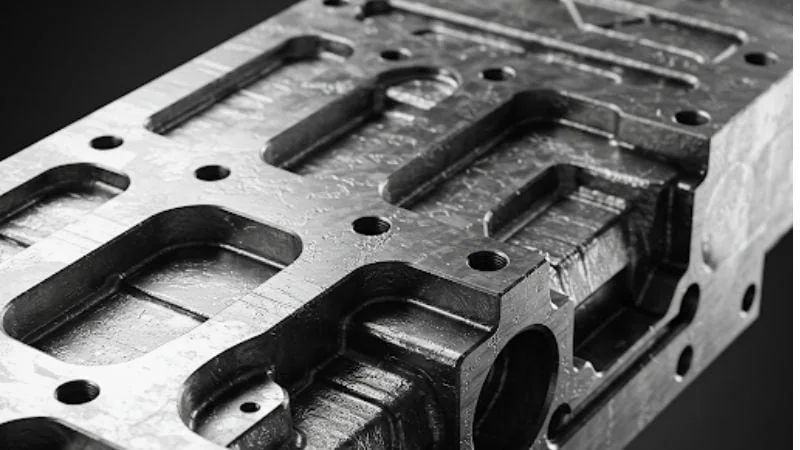
Automotive: Milling High-Silicon Aluminum Engine Blocks and Cylinder Heads
This is the classic high-volume application for PCD tooling. The goal is to create perfectly flat deck surfaces on engine blocks and cylinder heads to ensure a gastight seal. The high-silicon aluminum used for these parts presents a dual challenge: achieving mirror finishes while resisting the intense abrasive wear.
Actionable Machining Strategy
- Tool Selection: Utilize face milling cutters with adjustable pockets designed for PCD inserts. A fine-grain PCD grade (e.g., 5-10 micron diamond size) is essential, as a sharper edge is better at cleanly shearing the soft aluminum matrix without dislodging the hard silicon particles.
- Cutting Parameters: Run at very high cutting speeds, typically in the 2,000-3,500 m/min (6,500-11,500 SFM) range. This high speed is critical for two silicon-related reasons: it reduces the thermal conductivity time, minimizing heat soak that causes BUE, and it helps the cutting edge “skip” over the silicon particles cleanly rather than plowing through them.
- Coolant Application: High-pressure flood coolant is non-negotiable. Its primary job here is not just cooling, but aggressively flushing away the highly abrasive silicon micro-chips. If these chips are not immediately evacuated, they can be recut, causing further tool wear and scoring the freshly machined surface.
- Pro Tip: For the mirror finish required by modern multi-layer steel (MLS) gaskets, use a PCD milling cutter with at least one “wiper” insert. This special insert has a small flat that smooths out the microscopic ridges left by the other inserts, overcoming the smearing tendency of the soft aluminum matrix.
Automotive: Turning and Grooving High-Silicon Aluminum Pistons
Pistons require precise diameters and perfectly formed ring grooves to control combustion and oil consumption. The high-silicon content provides wear resistance in the engine but makes achieving the required precision a significant challenge. The primary obstacle is maintaining the tool’s sharp profile against constant silicon abrasion.
Actionable Machining Strategy
- Tool Selection: Specify custom-ground PCD-tipped inserts3. Standard carbide tools will have their sharp corners rounded by silicon abrasion almost immediately, resulting in out-of-spec grooves. The diamond edge is the only practical way to maintain a sharp, precise groove profile for thousands of parts.
- Cutting Parameters: Employ a Constant Surface Speed (CSS) mode on the CNC lathe. This is vital because it ensures the cutting edge is always moving fast enough to stay ahead of the silicon-induced BUE formation, which is a constant threat when turning the gummy aluminum matrix.
- Process Control: When grooving, program the tool to reduce the feed rate by 30-50% just before it enters the cut. The initial impact on the hard silicon particles can easily micro-chip even a tough PCD edge. A gentler entry prolongs tool life significantly when dealing with this composite-like material.
- Pro Tip: Because the piston surface can be damaged by silicon particle drag-out, orient the part and tool so that gravity and coolant flow assist in pulling chips away from the finished surface, especially during horizontal turning operations.
Aerospace & Hydraulics: Finishing High-Silicon Aluminum Pump and Valve Bodies
In these critical components, the challenge is achieving a flawless internal bore surface finish despite the presence of hard silicon particles. A microscopic scratch created by a silicon particle being dragged by the tool is not just a cosmetic flaw—it’s a potential leak path that can lead to catastrophic failure.
Actionable Machining Strategy
- Tool Selection: Use solid carbide boring bars with brazed PCD tips4. The extreme rigidity of this setup is essential to prevent any vibration that could cause the PCD tip to “hammer” against the hard silicon particles, which would lead to chatter marks and edge chipping. A sub-micron PCD grade provides the sharpest possible edge to cleanly shear the aluminum matrix without disturbing the silicon.
- Cutting Parameters: To get a mirror finish, use a very shallow depth of cut, often just 0.10-0.20 mm (0.004-0.008 in). This minimizes cutting pressure and heat, preventing the tool from digging in and dragging silicon particles across the delicate surface. Combine this with a slow, consistent feed rate of 0.05-0.10 mm/rev (0.002-0.004 in/rev).
- Machine Setup: High-speed boring requires a perfectly balanced tool and holder assembly. Any imbalance will cause vibration, which is amplified as the tool edge makes intermittent contact with the hard silicon inclusions, translating directly into chatter marks on the bore surface.
- Pro Tip: After boring, use a process like roller burnishing to further smooth the surface. The smooth, hard surface created by the PCD boring pass is an ideal starting point for burnishing, as there are no torn metal fragments to contend with.
Other Notable High-Silicon Aluminum Applications
Beyond the main examples, PCD is the required solution for a host of other parts where silicon’s abrasive nature is the primary obstacle:
- Transmission Cases: PCD is essential for maintaining flatness and true bore alignment across large, complex castings, preventing the dimensional instability that would otherwise result from rapid tool wear due to silicon abrasion.
- Brake Components: Critical for creating burr-free and finely finished internal bores in ABS manifold blocks. PCD prevents the micro-scratches from silicon drag-out that could cause hydraulic seals to fail over time.
- Aluminum Matrix Composites (AMCs): The ultimate test for any cutting tool. PCD is the only viable solution for these materials, where the extreme abrasiveness of ceramic reinforcements (like silicon carbide) makes them even more punishing to machine than standard high-silicon alloys.
Conclusion
In conclusion, the challenges of machining high-silicon aluminum are significant, but they are not insurmountable. The core problem stems directly from the material’s abrasive nature, which leads to rapid tool wear, poor surface quality, and process instabilities like Built-Up Edge. While conventional tools struggle, case studies from demanding industries like automotive and aerospace prove that PCD tooling is not just an incremental improvement—it is the definitive solution. By leveraging the exceptional hardness and wear resistance of diamond, PCD tools provide the tool life, precision, and stability required to transform this difficult-to-machine material into a reliably manufacturable one. For any modern operation seeking to machine high-silicon aluminum efficiently and profitably, adopting PCD tooling is an essential step toward success.
References
- Built-Up Edge (BUE)1 – A Wikipedia article detailing the phenomenon of Built-Up Edge in metal cutting, its causes, and effects.
- its unparalleled hardness, high thermal conductivity, and extreme wear resistance2 – An in-depth guide from ZYDiamondTools explaining the key material properties of PCD that make it effective.
- PCD-tipped inserts3 – ZYDiamondTools product page for standard and custom Polycrystalline Diamond inserts used in various machining applications.
- boring bars with brazed PCD tips4 – ZYDiamondTools product page for high-precision boring bars tipped with PCD or CBN for finishing operations.


