-
Whatsapp: +86 13526572721
-
Email: info@zydiamondtools.com
-
Address: AUX Industrial Park, Zhengzhou City, Henan Province, China
-
Whatsapp: +86 13526572721
-
Email: info@zydiamondtools.com
-
Address: AUX Industrial Park, Zhengzhou City, Henan Province, China

Hard Turning of Transmission Gears: PCBN Solutions for Bores, Faces, and Complex Profiles
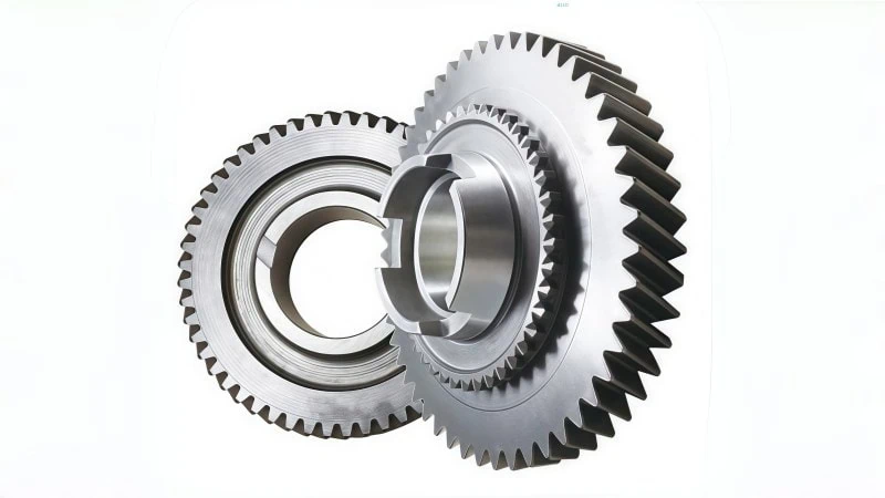
How can manufacturers replace grinding with hard turning for transmission gears while maintaining tight tolerances and tool life?
Hard turning1 replaces grinding by utilizing Polycrystalline Cubic Boron Nitride (PCBN) tooling2 with specific edge preparations and grades tailored for interrupted cuts, deep bores, and complex grooves. This process achieves surface finishes below Ra 0.4 microns and significantly reduces cycle times by eliminating coolant and wheel dressing, even on case-hardened steels up to 62 HRC.
Mastering Interrupted Cuts on Gear Faces
What is the primary cause of tool failure when hard turning gear faces featuring oil holes or splines?
The leading cause of failure is mechanical shock caused by the interrupted cut, which fractures the cutting edge. To prevent this, manufacturers must utilize high-content PCBN grades paired with a heavy negative chamfer edge preparation. This geometry redirects cutting forces into the body of the insert, allowing the tool to withstand the repeated impact as it exits and re-enters the hardened workpiece material.
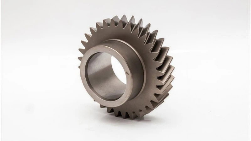
Case Study: Overcoming Edge Chipping on Gears with Oil Holes
In transmission manufacturing, the gear face is rarely a continuous surface. It often contains lubrication holes or keyways. When a cutting tool passes over these holes, it experiences a phenomenon known as an “interrupted cut3.”
Consider the mechanics of a milling operation versus a turning operation. In milling, the cutter constantly enters and exits the material, designed to handle impact. In standard turning, the tool is under constant load. When a hard turning tool encounters an oil hole, the cutting resistance drops to zero instantly. Upon re-entering the steel, the resistance spikes. This rapid cycle creates severe shock, similar to the impact forces seen in milling, but applied to a stationary tool tip.
Real-World Scenario:
A transmission plant was machining the face of an output gear made from 20CrMnTi (carburized to 60 HRC). The gear face had three large oil holes.
- The Problem: The standard PCBN insert was chipping after only 15 parts. The sudden impact at the oil hole caused the tip to break off.
- The Analysis: The shop was using a standard edge preparation4 meant for continuous cutting. The edge was too sharp to handle the impact load of the oil holes.
- The Solution: They switched to a heavy-duty edge preparation. This strengthened the cutting tip.
- The Result: Tool life increased to 80 parts per edge.
Key Takeaway: If your gear face has interruptions, standard continuous cutting parameters will fail. You must treat the operation as a high-impact zone.
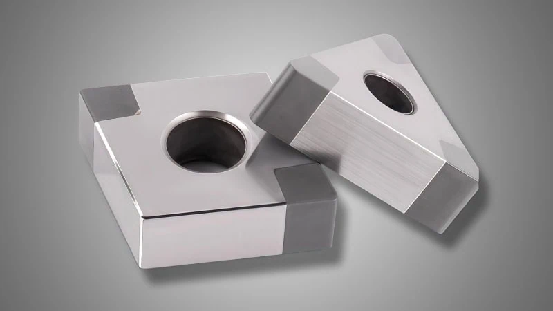
Optimizing Chamfer Angles to Protect the Cutting Edge
To survive the impact of an interrupted cut, the geometry of the cutting edge is critical. You cannot use a sharp edge on hardened steel interruptions. Instead, you must use a “Chamfer” (also called a T-land) and often a “Hone.”
The chamfer is a small angled flat ground onto the cutting edge. Its purpose is to redirect cutting forces. A sharp edge takes the force directly on the tip (shear stress), leading to breakage. A chamfer pushes the force down into the strong body of the insert (compressive stress).
Common Edge Preparations for Interrupted Cuts:
| Feature | Typical Specification | Function |
|---|---|---|
| Chamfer Angle | 25° – 35° | Changes the direction of the cutting force to protect the tip. |
| Chamfer Width | 0.15mm – 0.2mm | Determines how much of the edge is reinforced. Wider is stronger but increases tool pressure. |
| Hone (Radius) | 0.02mm – 0.03mm | Smooths the transition to prevent micro-chipping. |
Note: Specific chamfer angles and widths can vary depending on the insert substrate. Always verify the recommended edge prep with your insert provider before running production.
Why the Angle Matters:
If the angle is too small (too flat), the edge remains too weak. However, if the angle is too steep, it generates excessive heat. This heat can cause the workpiece to deform. Therefore, finding the balance is essential. For heavy interruptions, a wider, steeper chamfer is generally required to survive the impact.
Why High-Content CBN Grades are Mandatory for Interrupted Faces
Choosing the right grade is just as important as the geometry. PCBN (Polycrystalline Cubic Boron Nitride) comes in different compositions, generally split into “Low-Content” and “High-Content.”
For interrupted cuts on gear faces, High-Content PCBN is the only reliable choice.
The Difference in Composition:
- Low-Content CBN: Contains less CBN and more ceramic binder. It behaves similarly to a pure ceramic insert—excellent chemical and wear resistance, but brittle. It works best on smooth, continuous cuts.
- High-Content CBN: Contains a high percentage of CBN particles (often 85-90%) with a metallic binder.
The Material Structure Comparison:
Think of the difference between Cermet and Coated Carbide.
- Low-Content is like Cermet: extremely hard and heat resistant, but if you subject it to heavy shock, it fractures.
- High-Content is like a tough Cemented Carbide: The metallic binder acts as a matrix that holds the CBN particles together tightly, allowing the structure to absorb the energy of the “hammering” impact without shattering.
Consequently, when machining a gear face with splines or holes, low-content grades will suffer from catastrophic breakage. High-content grades might wear out faster due to friction, but they will not snap unexpectedly. In mass production, predictable wear is always preferred over unpredictable breakage.
Achieving Grinding-Class Precision in Gear Bores
Can hard turning truly match the cylindricity and surface finish standards of grinding for transmission gear bores?
Hard turning effectively replaces grinding for gear bores by combining high-rigidity clamping solutions, such as diaphragm chucks or full-grip jaws, with advanced PCBN wiper geometries. This setup controls roundness errors to within 3 microns and achieves surface finishes (Ra) consistently below 0.4 microns, all while reducing cycle times by eliminating the need for coolant and wheel dressing.
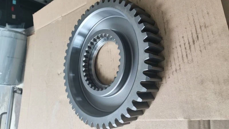
Strategies for Thin-Wall Gear Clamping to Prevent Deformation
The most significant barrier to precision in gear bores is not the cutting tool, but the fixture. Transmission gears, especially ring gears or sliding sleeves, often feature thin walls. When you clamp these parts with a standard 3-jaw chuck, the radial force distorts the gear into a triangular shape.
Once you machine the bore round and release the clamp, the gear springs back to its original shape. The result is a bore that looks like a three-leaf clover, a defect known as “tri-lobing.”
To prevent this, you must distribute the clamping force evenly across the entire circumference of the pitch diameter.
Recommended Clamping Solutions:
- Pie Jaws (Full-Grip Jaws): These are soft jaws machined to wrap nearly 360 degrees around the gear. They spread the pressure so no single point bears the load.
- Diaphragm Chucks: These systems use the elastic deformation of a metal plate to grip the part. They offer extreme repeatability and control clamping force very precisely.
Comparison of Clamping Methods for Thin-Wall Gears:
| Clamping Method | Contact Area | Risk of Deformation | Typical Roundness Error |
|---|---|---|---|
| Standard 3-Jaw Chuck | 3 Points | High (Tri-lobing) | > 0.015 mm |
| Pie Jaws (Full-Grip) | ~95% Coverage | Low | < 0.005 mm |
| Diaphragm Chuck | 360° Continuous | Very Low | < 0.002 mm |
Think of a collet chuck mechanism versus a standard jaw chuck. A collet wraps around the part, providing uniform pressure, whereas jaws apply point-loads. For thin-walled gears, a diaphragm chuck or pie jaws act similarly to a high-precision collet, preventing the “polygonization” effect common in standard clamping.
Obtaining Ra < 0.4 Surface Finish Without Secondary Operations
For decades, engineers believed only grinding could achieve a Surface Roughness (Ra)5 below 0.4 microns (µm). Today, PCBN tools with Wiper Geometry routinely achieve Ra 0.2 µm in hardened steel.
A standard cutting insert has a simple nose radius. As it moves across the bore, it leaves small peaks and valleys on the surface, similar to the scallop marks left by a ball-nose end mill during 3D surfacing. To smooth these out, you traditionally had to slow the feed rate down drastically, which hurts productivity.
The Wiper Advantage
A Wiper insert modifies the standard nose radius. It adds a small, flat straightening edge effectively “wiping” the surface smooth behind the cut.
- Standard Insert: At a feed rate of 0.15 mm/rev, might produce Ra 0.8 µm.
- Wiper Insert: At the same feed rate (0.15 mm/rev), produces Ra 0.3 µm.
Operational Data:
In a recent case involving a planetary gear bore (HRC 60), switching to a high-precision wiper grade allowed the manufacturer to double the feed rate from 0.08 mm/rev to 0.16 mm/rev. The surface finish improved from Ra 0.5 to Ra 0.25, completely eliminating the need for a final honing operation.
Pro Tip: When programming for wipers, ensure the tool approach angle is set correctly (usually 95° or 93°) to engage the wiper flat properly.
Correcting Taper and Roundness Issues in Deep Bore Turning
Deep bores present a challenge called “deflection.” As the boring bar extends further into the gear, the cutting forces push the tool away from the wall. This is physics at work: a long bar acts like a cantilever beam.
This deflection causes Taper. The bore ends up narrower at the bottom (where the tool is pushed away) and wider at the entrance.
Solutions for Controlling Taper:
- Bar Material Selection:
- Steel Bars: Good for Length-to-Diameter (L/D) ratios up to 3:1.
- Carbide Bars: Essential for L/D ratios up to 5:1. Carbide has a Young’s Modulus6 roughly three times higher than steel, making it much stiffer and resistant to bending.
- Spring Passes (Spark-out):
After the finish cut, run the tool over the surface again at the same diameter but without advancing the X-axis. This cuts away the material left behind by the deflection. However, be cautious: PCBN hates “rubbing,” so this should only be done if absolutely necessary for tolerance. - Taper Compensation:
Modern CNC lathes allow you to program a slight angle to counteract the push-off. If the bore is 0.01mm smaller at the bottom, program the tool to move X-0.01mm deeper as it reaches the bottom.
Tool Wear Compensation
In hard turning, the PCBN edge wears gradually. This wear creates a phantom “taper” or size change over time. Operators must monitor the bore size frequently. For tight tolerance gears (IT5 or IT6 class), automatic in-process gauging probes are highly recommended to adjust the tool offset every few parts automatically.
Hard Grooving and Splining Strategies
Why is machining deep grooves in hardened transmission gears considered one of the most risky operations for tool life?
Hard grooving creates a “closed” cutting environment where heat becomes trapped on all three sides of the insert, rapidly accelerating wear. To prevent catastrophic failure, manufacturers must utilize specialized PCBN tooling with vacuum-brazed tips and laser-ablated chip breakers that force chips to evacuate the narrow channel rather than packing against the workpiece.
Application Focus: Machining Synchronizer Hub Selector Grooves
The synchronizer hub is the heart of a manual or dual-clutch transmission. The most critical feature on this component is the “selector groove” (or fork groove). This is where the shift fork engages to move the gear. These hubs are typically induction hardened to 58-62 HRC.
Traditionally, manufacturers ground these grooves. However, grinding wheels wear down quickly on the corners, making it difficult to maintain the required squareness. Hard turning the groove with PCBN is significantly faster and maintains better profile consistency.
The “Plunge and Side-Turn” Method:
Unlike standard turning, you cannot simply drag the tool across the part. The most effective strategy involves a specific sequence:
- Plunge: The tool feeds radially into the groove to full depth.
- Relieve: The tool backs off slightly (microns) to reduce pressure.
- Side Turn: The tool feeds axially to finish the side walls.
Case Study: Cycle Time Reduction
A major automotive Tier 1 supplier switched from grinding to hard turning for a truck transmission hub.
- Grinding Cycle: 45 seconds per part.
- PCBN Turning Cycle: 12 seconds per part.
- Quality: The PCBN tool held a width tolerance of +/- 0.025mm effortlessly.
Note: Ideally, the tool width should be approximately 70-80% of the final groove width. This allows room for the tool to maneuver and finish the side walls without cutting on both sides simultaneously, which causes chatter.
Custom Tooling Designs for Restricted Clearance Areas
Transmission gears are often clustered together on a shaft. This creates a geometric nightmare: there is often very little room for the tool holder to fit between the gear teeth to reach the groove.
A standard ISO tool holder is usually too bulky. It will collide with the adjacent gear face before the insert reaches the bottom of the groove. Therefore, Custom “Dog-Leg” or “Gooseneck” Holders are essential.
Designing for Rigidity in Tight Spaces:
When you thin down a tool holder to fit a tight gap, you lose rigidity. A thin tool acts like a weak boring bar; it vibrates. In hard grooving, vibration kills PCBN inserts instantly.
To solve this, tool designers use Carbide-Reinforced Shanks. Instead of making the whole tool out of steel, the neck portion is made of solid carbide brazed to a steel shank.
Comparison of Tool Holder Materials for Grooving:
| Material | Stiffness (Young’s Modulus) | Vibration Resistance | Clearance Capability |
|---|---|---|---|
| Standard Steel | ~200 GPa | Low | Poor (Must be thick) |
| Heavy Metal (Tungsten Alloy) | ~350 GPa | Medium | Good |
| Solid Carbide Reinforced | ~600 GPa | High | Excellent (Can be very thin) |
Disclaimer: Custom tooling capabilities vary by manufacturer. Always provide your tool supplier with a detailed 3D model of the gear cluster to check for collision interference before ordering.
Chip Control Techniques for Deep Grooves in Hardened Steel
Chip control is the single biggest operational challenge in hard grooving.
In standard turning, the chip flows away freely. In grooving, the chip is trapped between two walls. If the chip does not break, it forms a “ribbon.” This ribbon can wrap around the part, scratching the surface you just machined. Or worse, it can jam between the tool and the wall, snapping the insert. This is often called “chip packing.”
The Solution: Laser-Ablated Chip Breakers
Standard PCBN tips are usually flat. They have no geometry to break the chip. For grooving, this is unacceptable. Leading manufacturers now use lasers to etch 3D structures directly onto the super-hard PCBN surface.
How It Works:
- Constriction: The laser-etched geometry narrows the path for the chip.
- Curl: As the hot, hardened steel7 chip flows over the geometry, it is forced to curl tightly.
- Breakage: The curl becomes so tight that the hardened chip snaps into small “C” or “6” shapes.
These small chips are easily ejected from the groove by the coolant or air blast. Without this geometry, the chip effectively becomes a saw blade, damaging both the part and the tool holder.
Matching PCBN Grades to Transmission Gear Materials
Does the specific type of steel used in a transmission gear actually change which PCBN grade you should buy, or is hardness the only factor that matters?
While hardness is important, the chemical composition of the gear steel is the deciding factor for tool life. Carburized steels like 20CrMnTi require PCBN grades with ceramic binders (such as TiC or TiN) to resist chemical wear, whereas induction hardened steels like 42CrMo often require tougher, metallic-binder grades to handle inconsistent hardness depths.
Tailoring Grade Selection for 20CrMnTi vs 42CrMo
Not all hardened steels behave the same way under the cutting tool. In the transmission industry, you typically encounter two main categories of material. Each interacts with PCBN differently due to the “binder” used in the insert.
The binder is the glue that holds the CBN particles together. Matching this glue to the steel is critical.
1. Carburized Steel (Example: 20CrMnTi, SAE 8620)
This is the standard for high-stress gears. The surface is rich in carbon.
- The Challenge: At high cutting temperatures, the iron in the gear loves to react chemically with PCBN. This causes “crater wear” on the top of the insert.
- The Solution: Use a Low-Content PCBN with a Ceramic Binder (TiC or TiN). Ceramics are chemically inert. They act like a thermal shield, preventing the gear material from reacting with the tool.
2. Induction Hardened Steel (Example: 42CrMo, SAE 4140)
This is common for shafts and hubs.
- The Challenge: Induction hardening can be uneven. You might hit “soft spots” or transition zones.
- The Solution: A ceramic binder might be too brittle here. Instead, use a grade with a Metallic Binder. It offers better toughness to handle the slight variations in material structure without chipping.
Comparison of Grade Strategies:
| Material Type | Typical Hardness | Primary Wear Mode | Recommended PCBN Binder |
|---|---|---|---|
| 20CrMnTi (Carburized) | 58-62 HRC | Chemical / Crater Wear | Ceramic (TiC/Al2O3) |
| 42CrMo (Induction) | 52-58 HRC | Abrasive / Impact | Metallic / Mixed |
Note: Steel compositions vary by region (e.g., Chinese GB standards vs. American SAE). Always confirm the exact alloying elements with your steel supplier before finalizing a PCBN grade.
The Correlation Between Gear Hardness (HRC 58-62) and Tool Life
It sounds backwards, but softer steel can actually destroy a PCBN tool faster than harder steel.
PCBN tools are designed to work in a specific “Sweet Spot,” typically between HRC 58 and HRC 62.
How PCBN Works (The “Hot Cutting” Principle):
PCBN tools do not operate like a High-Speed Steel (HSS) tool cutting aluminum. They do not shear material cold. Instead, they rely on thermal softening. The tool moves so fast that the friction heats the steel directly in front of the edge to nearly 700°C. At this temperature, the steel becomes plastic and shears away easily.
Why “Soft” Hard Steel (HRC 50-55) is Dangerous:
If the gear is only HRC 50-55, it does not generate enough frictional heat.
- Insufficient Plasticization: The steel remains solid and abrasive.
- Binder Wear: The abrasive steel eats away the binder holding the CBN particles.
- Result: The tool wears out rapidly due to abrasion, not heat.
Therefore, if your heat treatment process is inconsistent and delivers gears at HRC 54 instead of HRC 60, your tool life will likely drop, not improve.
Analyzing Flank Wear Patterns to Optimize Cutting Speeds
You can “read” your worn inserts to determine if your cutting speed (Vc) is correct for the specific gear material. The wear pattern tells a story about the heat zone.
1. Excessive Flank Wear (VB)
- Appearance: A flat, rough patch on the side of the cutting edge.
- Diagnosis: The speed is likely too low. You are not generating enough heat to soften the gear surface, causing the hard carbides in the steel to grind away the tool.
- Action: Increase the cutting speed (Vc) to generate more heat.
2. Crater Wear
- Appearance: A scooped-out hollow on the top of the insert.
- Diagnosis: The speed is too high. The chemical reaction between the steel and the tool is happening too fast. The heat is dissolving the binder.
- Action: Reduce the cutting speed.
3. Chipping (Fracture)
- Appearance: The cutting edge is jagged or broken.
- Diagnosis: This is often a mechanical issue, but can be related to “Built-Up Edge” (BUE). If the speed is too low, the material sticks to the tool and then breaks away, taking a piece of the tool with it.
- Action: Verify machine rigidity first. If rigidity is good, try increasing the speed slightly to prevent material sticking.
Optimum Wear Guide:
| Wear Pattern | Likely Cause | Adjustment Strategy |
|---|---|---|
| Rapid Flank Wear | Speed too low (Abrasion) | Increase Speed (+10%) |
| Crater Wear | Speed too high (Chemical) | Decrease Speed (-10%) |
| Built-Up Edge | Speed too low (Adhesion) | Increase Speed (+15%) |
By balancing the speed to keep the wear on the flank (side) rather than the crater (top), you maximize the number of gears produced per edge.
Conclusion
Transitioning from grinding to hard turning for transmission gears offers immense efficiency gains, but it requires a specialized approach. Success depends on mastering the interaction between the tool edge and the workpiece feature. By selecting high-content CBN for interrupted faces, utilizing wiper geometry and rigid clamping for bores, and applying laser-etched chip breakers for grooves, manufacturers can achieve grinding-level precision at turning speeds.
Ultimately, the key is matching the grade to the steel’s chemical composition and hardness. When these factors align, hard turning becomes not just a faster alternative, but a superior manufacturing process for modern gearbox components. For further assistance with your specific application, contact us.
References
- Hard turning1 – ZYDiamondTools article explaining the fundamentals of hard turning and comparing it to the traditional grinding process.
- Polycrystalline Cubic Boron Nitride (PCBN) tooling2 – ZYDiamondTools product category page showcasing PCBN tooling options.
- interrupted cut3 – ZYDiamondTools guide on how to effectively machine materials with interrupted surfaces using PCBN tools.
- edge preparation4 – ZYDiamondTools technical post about the importance of edge radiusing and chamfering for insert longevity.
- Surface Roughness (Ra)5 – Wikipedia entry explaining surface roughness parameters, including Ra.
- Young’s Modulus6 – Wikipedia article defining Young’s Modulus and its relevance to material stiffness.
- hardened steel7 – ZYDiamondTools article discussing why CBN inserts are essential for successfully machining hardened steel components.


