-
Whatsapp: +86 13526572721
-
Email: info@zydiamondtools.com
-
Address: AUX Industrial Park, Zhengzhou City, Henan Province, China
-
Whatsapp: +86 13526572721
-
Email: info@zydiamondtools.com
-
Address: AUX Industrial Park, Zhengzhou City, Henan Province, China
Flat vs. Ball Nose vs. Corner Radius: How Do You Choose the Right PCD End Mill for Your Application?
- Knowledge, PCD & CBN Tools Knowledge
- -2025-05-14
- - byKevin Ray

When it comes to machining with Polycrystalline Diamond (PCD) end mills, you’re faced with a few key geometric choices—flat, ball nose, or corner radius—so how do you determine which one is truly the best fit for your specific job?
Choosing the right PCD end mill hinges on understanding your specific application: flat end mills are for creating 2D features like flat surfaces and sharp corners; ball nose end mills excel at 3D contouring and complex curves; while corner radius end mills offer a balance, providing strength and creating filleted edges, all amplified by PCD’s benefits in non-ferrous and abrasive materials, making them a focus for PCD End Mills for Non-Ferrous Abrasive Machining Needs1.
Table of Contents
ToggleHow Do Their Geometries Fundamentally Differ?
So, what really sets the shapes of PCD (Polycrystalline Diamond) flat, ball nose, and corner radius end mills apart from each other?
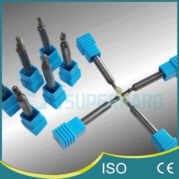
These PCD end mill types are primarily distinguished by their tip geometry: flat end mills have a square tip for creating flat surfaces and sharp corners; ball nose end mills feature a fully rounded tip ideal for machining 3D curves and complex contours; and corner radius end mills offer a flat bottom with rounded corners, blending the characteristics of the other two for increased strength and producing filleted edges.
Now, let’s explore each of these geometries in more detail.
PCD Flat End Mills: Understanding Their Square Profile and Cutting Action
Imagine a miniature, super-hard chisel made with a PCD cutting edge; that gives you a good idea of a PCD flat end mill.
Their most defining feature is a square profile at the tip. This means the bottom cutting edges meet the side cutting edges at a sharp, typically 90-degree angle. Consequently, when a flat end mill machines a pocket or a slot, it aims to create a flat bottom and crisp, sharp inside corners.
The cutting action of a PCD flat end mill is primarily with its periphery (the sides) for milling profiles and with its end face (the bottom) for creating flat surfaces or plunging. Because PCD is incredibly wear-resistant, a key aspect of its Polycrystalline Diamond (PCD) Key Properties Explained2, these end mills maintain their sharp square profile for extended periods, especially when machining abrasive non-ferrous materials like high-silicon aluminum or composites. This consistent sharpness is crucial for producing accurate features.
Think about milling a simple rectangular pocket in an aluminum block. A PCD flat end mill would be used to machine the flat bottom of the pocket and the straight, vertical walls, aiming for those sharp 90-degree internal corners where the walls meet the floor.
PCD Ball Nose End Mills: Exploring the Full Radius for 3D Contouring
Next, picture the very tip of a ballpoint pen, but engineered to cut tough materials – this is similar to a PCD ball nose end mill.
The key geometrical feature here is the full radius at the tool tip, meaning the end of the cutter is a perfect hemisphere. This rounded tip allows the end mill to engage the workpiece smoothly from various angles. Therefore, it’s exceptionally well-suited for 3D contouring and machining complex, flowing surfaces without leaving sharp steps. Understanding Why to Use PCD Ball Nose End Mills and How to Choose3 can provide further insight into their specific advantages.
Its cutting action is quite different from a flat end mill, especially when finishing. As it moves across a surface, the rounded tip creates very small cusps, or scallops, between passes. By controlling the step-over (how much the tool moves over on each pass), machinists can produce very smooth, intricate 3D shapes. The PCD tip ensures this precise radius is maintained for a long time, which is vital for consistency in applications like mold making for plastic injection or die casting, where complex curvatures need to be accurately reproduced. For instance, when creating the intricate curved surfaces of a turbine blade from a composite material, a PCD ball nose end mill would be selected to trace those complex paths accurately.
PCD Corner Radius End Mills: The Hybrid Design for Strength and Fillets
Now, let’s consider the PCD corner radius end mill. This tool is like a clever blend of the flat and ball nose designs.
It features a generally flat bottom, much like a flat end mill, but with one crucial difference: its corners are not sharp. Instead, they have a specific rounded radius, making it a hybrid design. This small radius at the corner is a game-changer for a couple of reasons.
First, it significantly increases the strength of the cutting edge compared to a standard flat end mill. Those sharp 90-degree corners on a flat end mill can be prone to chipping under stress, especially in tough materials or during aggressive cutting. By rounding these corners, the stress is distributed over a larger area, making the tool more robust.
Second, this geometry is designed to produce a fillet, or a rounded internal edge, where a wall meets a floor in a machined part. This is often a design requirement to reduce stress concentrations in the final component.
The size of the corner radius can vary, and it’s an important specification. For example, a corner radius end mill might be described as as having a 0.5mm corner radius. This specific radius is what will be replicated on the workpiece. It’s worth noting that the available corner radii and other tool dimensions can differ between suppliers, so it’s always a good idea to check the manufacturer’s specifications. PCD again plays a vital role here by ensuring that this precise corner radius is maintained throughout the tool’s life, even when machining abrasive materials encountered in aerospace components made from carbon fiber reinforced plastics (CFRP).
A Comparative Glance: Key Geometrical Distinctions at the Cutting Edge
To really see how these tools differ, let’s put their key geometric features side-by-side. While parameters like the number of flutes or helix angle are also part of their geometry and affect performance, the tip is the most fundamental differentiator for these three types.
Feature | PCD Flat End Mill | PCD Ball Nose End Mill | PCD Corner Radius End Mill |
---|---|---|---|
Tip Shape | Square/Flat | Full Radius (Hemispherical) | Flat with Rounded Corners |
Bottom Edge | Straight, meets side at 90° | Continuous Curve | Straight, with corner radii |
Corner Type | Sharp (90 degrees) | Not Applicable (fully round) | Rounded (Specific Radius) |
Primary Use Based on Geometry | Creating flat surfaces, sharp internal corners | Machining 3D contours, curved surfaces | Creating flat surfaces with filleted internal corners, enhanced corner strength |
Essentially, the choice of geometry at the cutting edge dictates how the PCD end mill interacts with the material and the kind of shapes it can efficiently produce. Understanding these basic geometric differences is the first step towards selecting the right tool for your specific machining needs.
What Are the Ideal Machining Applications for Each PCD End Mill Type?
So, you know their shapes, but where do these different PCD (Polycrystalline Diamond) end mills truly shine in the workshop?
PCD flat end mills are ideal for 2D operations like creating flat surfaces, shoulders, and slots; PCD ball nose end mills excel in complex 3D contouring, mold making, and achieving smooth finishes on curved surfaces; and PCD corner radius end mills are best for pocketing operations requiring a specific corner radius, creating fillets, and general milling where edge strength is paramount, especially in abrasive materials.
Let’s break down the best uses for each type.
PCD Flat End Mills: Best Uses for 2D Milling, Slotting, and Facing
PCD flat end mills are the workhorses for many common machining tasks, particularly when dealing with non-ferrous metals and abrasive non-metals where PCD’s wear resistance offers significant advantages.
- 2D Milling: This involves creating features on flat planes or stepped flat planes.
- Profiling: Cutting the outside shape or outline of a part. For instance, shaping the perimeter of an aluminum base plate for an electronic enclosure.
- Shoulder Milling: Creating a step or shoulder in a workpiece. Imagine machining a precise ledge on a component where another part will sit.
- Slotting: This means cutting a groove or slot into a workpiece.
- A common example is milling keyways in shafts made of brass or cutting straight channels in a composite panel for wiring. The PCD edge ensures the slot width remains consistent over many parts.
- Facing: This is the process of making a large surface flat and smooth.
- For instance, creating a perfectly flat mounting surface on a cast aluminum gearbox housing. A larger diameter PCD flat end mill or a dedicated PCD face mill (which often uses multiple PCD inserts similar in principle to flat end mill cutting edges) can quickly produce a high-quality surface finish.
In all these applications, the sharp corners of the PCD flat end mill create defined edges and flat bottoms. The long life of the PCD ensures these features are accurately reproduced, part after part.
PCD Ball Nose End Mills: Excelling in 3D Profiling, Mold Making, and Finishing Passes
When the job involves complex curves and three-dimensional shapes, PCD ball nose end mills take center stage. Their fully rounded cutting tip is designed for smooth transitions and intricate details.
- 3D Profiling and Contouring: This is where ball nose end mills truly excel. They are used to machine complex surfaces, such as:
- Aerospace components: Creating the aerodynamic surfaces of parts made from lightweight aluminum alloys or carbon fiber composites. For example, machining the complex airfoil shape of a fan blade.
- Medical implants: Manufacturing custom orthopedic implants with organic, curved shapes from materials like PEEK or titanium (though PCD is more common for non-ferrous and non-metallic).
- Mold Making: These tools are essential in creating molds and dies.
- Injection molds: Machining the cavities and cores of molds used for producing plastic parts, from intricate automotive components to detailed consumer electronics casings. PCD ball nose end mills are particularly effective when machining graphite electrodes used in Electrical Discharge Machining (EDM)4 to create these mold features. The wear resistance of PCD is critical for maintaining the electrode’s precise shape, an area where PCD Tools for Graphite Machining5 show their value.
- Finishing Passes: For achieving a high-quality surface finish on contoured parts.
- After roughing out a shape, a PCD ball nose end mill is often used for the final passes, leaving a smooth surface that may require little to no hand polishing. Their ability to maintain a consistent radius is crucial for the final aesthetic and functional quality of the part.
The effectiveness of these operations relies on precise control of cutting parameters, such as step-over (the distance between adjacent tool paths), feed rate, and spindle speed. These parameters should always be optimized based on the specific material, machine capabilities, and recommendations from the tool supplier.
PCD Corner Radius End Mills: Best for Pocketing with Radii, Enhanced Edge Strength, and Producing Fillets
PCD corner radius end mills offer a versatile solution, combining features of both flat and ball nose tools, leading to unique application benefits.
- Pocketing with Specified Radii (Fillets): Many engineering designs require internal corners of pockets or slots to have a specific radius rather than a sharp corner. This is often done to:
- Reduce stress concentration: Sharp internal corners can be weak points. A fillet distributes stress more evenly, making the part stronger.
- Meet design specifications: For example, in automotive components like engine blocks or transmission parts made from high-silicon aluminum, specific corner radii are often mandated in pockets. A PCD Corner Radius End Mill6 machines the flat bottom of the pocket and simultaneously creates the precise rounded fillet in one operation.
- Robust General Milling: The rounded corners not only create fillets but also significantly increase the strength of the cutting edge compared to a standard flat end mill. This makes them:
- More resistant to chipping: Especially useful in interrupted cuts or when machining tougher abrasive materials like green ceramics or certain composites.
- Longer lasting in demanding applications: The enhanced edge strength contributes to extended tool life.
- Applications requiring a blend of flat surfaces and rounded transitions:
- For instance, in woodworking, creating panels with filleted edges, or in machining certain types of electronic housings from engineered plastics where both flat surfaces and internal radii are needed.
The choice of corner radius is critical and must match the design specification. PCD ensures this radius is accurately maintained for many parts, providing consistency and quality.
Material Considerations: Which Materials Maximize the Potential of These PCD Geometries?
While the geometry dictates the type of cut, the PCD material itself makes these end mills particularly effective in a range of challenging materials. Regardless of whether it’s a flat, ball nose, or corner radius design, using a PCD version of that tool is most advantageous when working with:
- Non-Ferrous Metals:
- High-Silicon Aluminum Alloys: Commonly found in automotive engine blocks, pistons, and aerospace components. These materials are very abrasive.
- Copper and Copper Alloys (Brass, Bronze): Used in electrical components, plumbing, and bearings.
- Abrasive Non-Metallic Materials:
- Composites:
- Carbon Fiber Reinforced Plastics (CFRP): Widely used in aerospace, automotive (especially performance vehicles), and high-end sporting goods. CFRP is notoriously abrasive and challenging to machine.
- Glass Fiber Reinforced Plastics (GFRP): Found in boat hulls, automotive parts, and industrial equipment.
- Graphite: Used extensively for EDM electrodes and in some high-temperature applications.
- Green Ceramics: Machining ceramic parts in their “green” (pre-sintered) state.
- Composites:
- Plastics and Polymers: Many engineered plastics and polymers, especially those that are abrasive or tend to cause built-up edge on conventional tools. Examples include PEEK, reinforced nylons, and some thermosets.
- Wood and Wood Composites: While less common for premium PCD tooling, applications exist in high-volume or abrasive wood product manufacturing (e.g., MDF, particleboard).
Why PCD for these? These materials are often highly abrasive, causing rapid wear on standard carbide tools. Some also have a tendency to stick to the cutting tool (built-up edge), leading to poor surface finish. PCD’s extreme hardness combats abrasive wear, and its low friction coefficient helps prevent material adhesion, resulting in longer tool life, better surface finishes, and the ability to maintain higher cutting speeds. This ultimately translates to increased productivity and lower cost per part in these specific material applications.
Why Opt for PCD Material in These Specific End Mill Geometries?
Given their distinct shapes and uses, what makes Polycrystalline Diamond (PCD) the go-to material choice for these particular end mills?
PCD is chosen for these end mill geometries primarily due to its exceptional hardness, leading to outstanding wear resistance and significantly longer tool life, especially in abrasive materials. This, in turn, allows for higher cutting speeds, improved surface finishes, and better overall cost-effectiveness in demanding applications compared to traditional tool materials.
Let’s unpack these advantages further.
The PCD Edge: Unpacking Superior Wear Resistance and Extended Tool Longevity
One of the standout features of PCD is its incredible hardness. Think of it like this: diamond is the hardest known natural material, and PCD, made of synthetic diamond particles sintered together, comes very close to that. So, what does this extreme hardness mean for an end mill?
It translates directly to superior wear resistance. When an end mill, whether it’s a flat, ball nose, or corner radius type, is cutting through material, especially abrasive ones like high-silicon aluminum or carbon fiber composites, it’s constantly battling friction and abrasion. Less hard materials, like even tough cemented carbides, will gradually wear down. Their cutting edges become dull, and their precise geometry is lost.
However, PCD’s hardness allows it to resist this abrasive wear far more effectively. This means:
- Extended Tool Longevity: A PCD end mill can last significantly longer than its carbide counterpart in the right applications. We’re not just talking about a small improvement; it can be 10, 50, or even over 100 times longer depending on the material being machined and the cutting conditions. For instance, in high-volume production of aluminum automotive components, a single PCD flat end mill might machine tens of thousands of parts, whereas a carbide tool might need replacing after only a few hundred or a thousand. This drastic reduction in tool changes brings substantial benefits in production efficiency.
This remarkable durability is a core reason why industries from aerospace to automotive rely on PCD for demanding milling tasks.
Achieving Higher Quality Surface Finishes with the Unique Properties of PCD
Beyond just lasting longer, PCD also helps in producing parts with a higher quality surface finish. How does it manage this? Several unique properties of PCD contribute:
- Maintaining a Sharp Cutting Edge: Because PCD resists wear so well, the cutting edges of the end mill remain sharper for a much longer period. A sharp edge shears the material cleanly, whereas a dulling edge tends to plow through or deform the material, leading to a rougher surface and potentially stressing the workpiece.
- Low Friction Coefficient: PCD has a low coefficient of friction with many workpiece materials, especially non-ferrous ones like aluminum. This means the material being cut is less likely to stick to the tool tip, a phenomenon known as built-up edge (BUE)7. BUE is a major culprit for poor surface finishes, as bits of the stuck material can break off and mar the workpiece surface or alter the cutting geometry.
- Chemical Inertness: With many non-ferrous materials, PCD is chemically inert, meaning it doesn’t readily react with the workpiece material. This further reduces the tendency for material adhesion.
The result? Smoother, cleaner surfaces directly from the machining process. For example, when using a PCD ball nose end mill for finishing passes on an aluminum mold for a high-visibility consumer product, the goal is often a near-mirror finish to reduce or eliminate post-machining polishing. PCD’s ability to maintain a keen, clean cutting edge is vital for achieving this.
PCD Impact on Machining Speeds and Feeds, Especially in Non-Ferrous and Abrasive Materials
If you can cut faster without sacrificing tool life or quality, you can make parts more quickly and efficiently. This is another significant advantage that PCD brings to the table, particularly when machining non-ferrous metals (like aluminum, copper, brass) and highly abrasive materials (like composites, graphite, and green ceramics).
PCD end mills can often be run at significantly higher machining speeds (revolutions per minute, RPM) and feed rates (how fast the tool moves through the material) compared to carbide tools in these materials. There are a couple of reasons for this:
- High Thermal Conductivity8: PCD conducts heat very well. During cutting, a lot of heat is generated at the cutting zone. PCD helps to draw this heat away from the cutting edge and into the body of the tool or the chips, preventing the edge from overheating and degrading quickly.
- Exceptional Wear Resistance: As we’ve discussed, PCD’s hardness allows it to withstand the stresses of high-speed cutting without rapid wear.
Consider the manufacturing of carbon fiber reinforced plastic (CFRP) components for the aerospace industry. These materials are incredibly light and strong but also extremely abrasive. Using PCD end mills (flat, ball nose, or corner radius depending on the feature) allows manufacturers to use much higher cutting speeds than would be feasible with carbide. This dramatically reduces cycle times, which is crucial for meeting production demands. For example, cutting speeds for PCD on CFRP can be in the range of 200-600 m/min or even higher, whereas carbide might be limited to 30-100 m/min to maintain reasonable tool life.
It’s important to remember that the achievable speeds and feeds will vary based on factors such as the specific grade of PCD used, the exact workpiece material and its condition, the rigidity and power of the machine tool, and the application of coolant. Always consult the tool manufacturer’s recommendations and perform tests to optimize parameters for your specific setup.
Evaluating the Cost-Effectiveness: When Does PCD Outperform Other Materials?
PCD end mills typically have a higher initial purchase price than comparable carbide tools. So, a key question is: when does this higher upfront investment make economic sense? The cost-effectiveness of PCD tooling becomes clear when you look beyond the initial price tag and consider the total cost of machining. Understanding the Total Cost of Ownership (TCO) for Superhard Tooling9 is essential here.
PCD tools tend to outperform other materials in terms of overall cost per part in several scenarios:
- High-Volume Production:
- Reduced Tool Changes: Longer tool life means fewer stops to change tools. This significantly reduces machine downtime and labor costs associated with tool changes.
- Consistent Part Quality: Less frequent tool changes and consistent wear mean more parts are produced within specification, reducing scrap and rework.
- Machining Difficult and Abrasive Materials:
- In materials like high-silicon aluminum, metal matrix composites (MMCs), CFRP, or graphite, standard carbide tools can wear out exceptionally fast. The frequent replacement of cheaper carbide tools can quickly add up to exceed the cost of a single, longer-lasting PCD tool.
- When Cycle Time Reduction is Critical:
- The ability to run PCD tools at higher speeds and feeds can lead to substantial reductions in machining cycle times. This means more parts can be produced on the same machine in the same amount of time, increasing throughput and lowering the overhead cost allocated to each part.
- Strict Surface Finish and Tolerance Requirements:
- If PCD delivers the required finish and accuracy directly off the machine, it can eliminate or reduce the need for secondary finishing operations (like grinding or polishing), saving time and money.
Let’s consider an automotive supplier producing aluminum transmission valve bodies. These parts often require good surface finishes and are made in high volumes. While a PCD flat end mill for facing operations might cost several times more than a carbide one, if it lasts 50 times longer and allows for a 30% reduction in cycle time, the savings in tooling cost per part, reduced downtime, and increased machine capacity quickly justify the initial investment.
Here’s a simplified look at factors influencing cost-effectiveness:
Factor | PCD End Mills | Carbide End Mills (in abrasive/non-ferrous) |
---|---|---|
Initial Tool Cost | Higher | Lower |
Tool Life | Significantly Longer | Shorter |
Cycle Time | Often Shorter (due to higher speeds/feeds) | Longer |
Downtime for Changes | Minimal | More Frequent |
Cost per Part | Potentially Much Lower in suitable applications | Can be Higher due to frequent replacements |
Ultimately, the decision involves a careful analysis of the specific application, material, production volume, and the full scope of manufacturing costs.
How Can You Select the Most Suitable PCD End Mill for Your Specific Task?
With all this information on geometries, applications, and PCD (Polycrystalline Diamond) benefits, how do you actually pinpoint the ideal PCD end mill for your specific machining job?
Selecting the most suitable PCD end mill involves first defining your machining goals and the desired outcome, then matching the end mill’s geometry (flat, ball nose, or corner radius) to the workpiece features and required tolerances. Critically, you must also analyze the workpiece material to ensure it’s a good fit for PCD, and finally, use a systematic approach or checklist to weigh these factors and make an informed decision.
Let’s walk through these steps to make your selection process clearer.
Defining Your Machining Goals: What Outcome Are You Targeting?
Before you can choose any tool, you need a clear picture of what you want to achieve. What’s the main goal of this particular machining operation? Asking yourself a few key questions can help sharpen this picture:
- What specific shape or feature are you creating? Are you trying to make a perfectly flat surface, cut a deep slot, machine a complex 3D curved shape (like a mold cavity), or create a pocket that needs rounded internal corners (fillets)?
- What level of surface finish is needed? Does the surface need to be very smooth and shiny, or is a standard machined finish acceptable? Is this a roughing operation (removing lots of material quickly) or a finishing operation (achieving final size and smoothness)?
- How precise does the part need to be? What are the dimensional accuracy and tolerance requirements for the feature you’re machining? Are we talking about general tolerances or high-precision work?
- What is the scale of production? Are you making just one or two parts, a small batch, or is this for mass production where thousands of identical parts are needed?
For example, if your goal is to quickly machine a flat base on 1,000 aluminum housings for an electronics project (a roughing or semi-finishing task with moderate tolerances), your tool considerations will differ from a situation where you need to create a single, highly precise graphite electrode with intricate 3D curves for an EDM application (a finishing task with very tight tolerances and high surface finish requirements). Clearly defining these goals is your first step.
Matching the End Mill Geometry to Workpiece Features and Tolerances
Once your goals are clear, you can start matching the PCD end mill’s geometry to the specific features of your workpiece. This is where our earlier discussions on what makes each tool shape unique become very practical.
- If your design calls for flat-bottomed pockets, square shoulders, or sharp internal corners, a PCD Flat End Mill is generally the right choice. Its square profile is designed to produce these features.
- If you’re dealing with 3D curves, complex contoured surfaces, or flowing organic shapes, then a PCD Ball Nose End Mill is your go-to tool. Its hemispherical tip allows it to smoothly machine these intricate forms.
- If your part requires flat bottoms in pockets but with specific rounded internal corners (fillets), or if you need extra strength at the tool’s corners for general milling in abrasive materials, then a PCD Corner Radius End Mill is the logical selection.
Beyond the basic shape, “tolerances” – the acceptable limits of variation in a dimension – are crucial. The precision of the PCD end mill itself, including its diameter, the exact radius of a ball nose tip, or the specific corner radius on a corner radius tool, directly impacts your ability to achieve tight workpiece tolerances. Factors like the tool’s runout (how precisely it spins on its axis) and the overall condition and rigidity of your milling machine also play a significant role here.
When selecting a tool, critical specifications such as the tool diameter, length of cut, and (for corner radius tools) the specific radius value must be carefully chosen to match the feature’s size, depth, and design requirements. It’s always a good practice to check with your tooling supplier for their available range of these specifications, as options can vary.
Workpiece Material Analysis: A Critical Factor in PCD Tool Selection
This is a very important checkpoint. While PCD is a remarkable cutting tool material, it’s not a universal solution for all workpiece materials.
First, let’s reiterate where PCD truly shines (as detailed in earlier sections):
- Non-ferrous metals: Especially high-silicon aluminum alloys, copper, brass, and bronze.
- Abrasive non-metallic materials: Composites like Carbon Fiber Reinforced Plastics (CFRP) and Glass Fiber Reinforced Plastics (GFRP), graphite, green (unsintered) ceramics, and some engineered plastics.
Now, critically, there are materials you should avoid machining with PCD tools:
- Ferrous materials: This includes all types of steel, stainless steel, and cast iron. At the high temperatures generated during cutting these materials, a chemical reaction can occur between the carbon in the PCD and the iron in the workpiece. This leads to rapid tool wear (often called diffusion wear or graphitization) and makes PCD unsuitable for these applications. Standard carbide or ceramic tools are typically used for ferrous materials.
Even within the range of PCD-friendly materials, the specific alloy or composite can influence the choice. For instance, some PCD grades are engineered to be tougher and more resistant to chipping, making them better suited for interrupted cuts or particularly aggressive composite materials. If you’re dealing with a very specific or challenging non-ferrous alloy or composite, it can be beneficial to consult with your PCD tool supplier. They often have deep expertise and may recommend a particular PCD grade that is optimized for your material.
Practical Selection Guide: A Checklist for Choosing Between PCD Flat, Ball Nose, and Corner Radius End Mills
To bring all these considerations together, here’s a practical checklist to guide you in selecting the most suitable PCD end mill for your task. Ask yourself these questions:
- What is the primary feature I need to machine?
- Flat surface, slot, or square shoulder? → Likely PCD Flat End Mill.
- Complex 3D curve, contoured surface, or intricate mold cavity? → Likely PCD Ball Nose End Mill.
- Pocket with a flat bottom but requiring a specific rounded internal corner (fillet)? → Likely PCD Corner Radius End Mill.
- What is the workpiece material?
- Is it a non-ferrous metal (e.g., aluminum, copper), a composite (CFRP, GFRP), graphite, or green ceramic? → PCD is a strong candidate.
- Is it steel, stainless steel, or another ferrous material? → PCD is NOT suitable. Look for other tool materials.
- Are sharp internal corners (90-degree) essential for the design?
- Yes → PCD Flat End Mill.
- Is the main task to create smooth, flowing 3D surfaces?
- Yes → PCD Ball Nose End Mill.
- Does the design specify internal radii (fillets) at the junction of walls and floors?
- Yes, and a specific radius value is given → PCD Corner Radius End Mill (ensure the tool’s corner radius matches the specification).
- For general flat surface milling in abrasive materials, is maximizing tool corner strength a higher priority than achieving absolutely sharp internal corners?
- Yes → A PCD Corner Radius End Mill might offer better durability.
- What is the target surface finish and dimensional accuracy?
- All PCD tools can produce excellent finishes in their ideal applications due to the material’s properties. However, for the very finest finishes on complex 3D surfaces, a PCD Ball Nose End Mill used in a finishing pass is often preferred. Ensure the chosen tool diameter and geometry are appropriate for the required tolerances.
- What are the production volume and overall cost considerations?
- As discussed previously, the higher initial cost of PCD is often justified in high-volume production or when machining very abrasive materials due to longer tool life, reduced downtime, and faster cycle times.
- What are the specific dimensional needs for the tool itself?
- Consider the required cutting diameter, length of cut needed to reach the feature, and, if applicable, the exact corner radius for a corner radius tool. These details must match your part geometry and machine setup.
By thoughtfully working through these questions, you can systematically narrow down your options and select the PCD end mill geometry that is best equipped to deliver the quality, efficiency, and tool life you need for your specific machining task. Remember, when in doubt, consulting with experienced application engineers from your tooling supplier can provide invaluable guidance.
Conclusion
Choosing the right PCD end mill—be it flat, ball nose, or corner radius—doesn’t have to be a complex puzzle. By understanding the fundamental differences in their geometry, recognizing their ideal applications, appreciating the significant advantages PCD material brings to these designs, and following a clear selection process, you can confidently pick the optimal tool. This informed approach ensures you leverage the full potential of PCD tooling, leading to higher quality parts, increased efficiency, and better overall value in your machining operations, especially when working with challenging non-ferrous and abrasive materials.
References
- PCD End Mills for Non-Ferrous Abrasive Machining Needs1 – ZYDiamondTools blog post discussing the suitability of PCD end mills for non-ferrous and abrasive materials.
- Polycrystalline Diamond (PCD) Key Properties Explained2 – ZYDiamondTools article detailing key properties of PCD like hardness, toughness, and wear resistance.
- Why to Use PCD Ball Nose End Mills and How to Choose3 – ZYDiamondTools guide on the benefits and selection of PCD ball nose end mills.
- Electrical Discharge Machining (EDM)4 – Wikipedia article explaining the principles of Electrical Discharge Machining.
- PCD Tools for Graphite Machining5 – ZYDiamondTools blog post on selecting PCD tools for graphite machining.
- PCD Corner Radius End Mill6 – ZYDiamondTools product page for PCD Corner Radius End Mills.
- built-up edge (BUE)7 – Wikipedia article explaining built-up edge in machining.
- Thermal Conductivity8 – Britannica article defining thermal conductivity.
- Total Cost of Ownership (TCO) for Superhard Tooling9 – ZYDiamondTools guide to understanding TCO for superhard tooling and abrasives.
ZY Superhard Tools Co., Ltd.
Do you have any needs for PCD tools or diamond grinding wheels? We can customize products to meet your specific requirements. If you have any ideas or requests, feel free to reach out—we’ll respond within 24 hours!
Do you have any needs for PCD & CBN tools or diamond grinding wheels? We can customize products to meet your specific requirements. If you have any ideas or requests, feel free to reach out—we’ll respond within 24 hours!
Post Categories
Product Categories
About Company
Related Posts
Mastering PCD Countersinking for aerospace Composites: Advanced Techniques for Optimal Performance and Hole Quality
Master PCD countersink drilling for aerospace composite. Your guide to optimal PCD tool selection, design insights, and process control for
Which Diamond Grinding Wheel is Best for Your Tungsten Carbide Project?
Learn to select the best diamond grinding wheel for tungsten carbide. Our guide covers key specs, types, applications, and tips
How Do You Select the Right Aerospace Grinding Tools to Overcome Key Manufacturing Challenges?
Select the right aerospace grinding tools to overcome manufacturing challenges. Learn about tool types, materials, precision, and critical success factors.
How Can You Maximize Hard Turning Success with CBN Inserts: From Selection to Troubleshooting?
Achieve optimal hard turning with CBN inserts. Our guide details selection, application best practices, performance optimization, & troubleshooting common problems.
Subscribe
Simply enter your email below and click “Subscribe” to stay connected with everything new and exciting.