-
Whatsapp: +86 13526572721
-
Email: info@zydiamondtools.com
-
Address: AUX Industrial Park, Zhengzhou City, Henan Province, China
-
Whatsapp: +86 13526572721
-
Email: info@zydiamondtools.com
-
Address: AUX Industrial Park, Zhengzhou City, Henan Province, China

CBN Inserts for Slewing Bearing Raceways: A Complete Guide
What are the specific advantages and technical requirements of using CBN inserts to replace grinding in the machining of hardened slewing bearing raceways?
Employing Cubic Boron Nitride (CBN) inserts for slewing bearing raceways enables manufacturers to replace slow grinding processes with high-efficiency hard turning1, achieving surface roughness levels of Ra 0.4 μm on HRC 58-63 induction hardened steel. Optimizing this process requires the use of Solid CBN inserts in round geometries (RCGX/RNGN) with negative edge preparation to withstand the severe interrupted cutting2 caused by oil holes, ensuring both dimensional accuracy and extended tool life.
Critical Challenges in Hard Turning Bearing Raceways
What makes machining slewing bearing raceways significantly more difficult than standard hard turning operations?
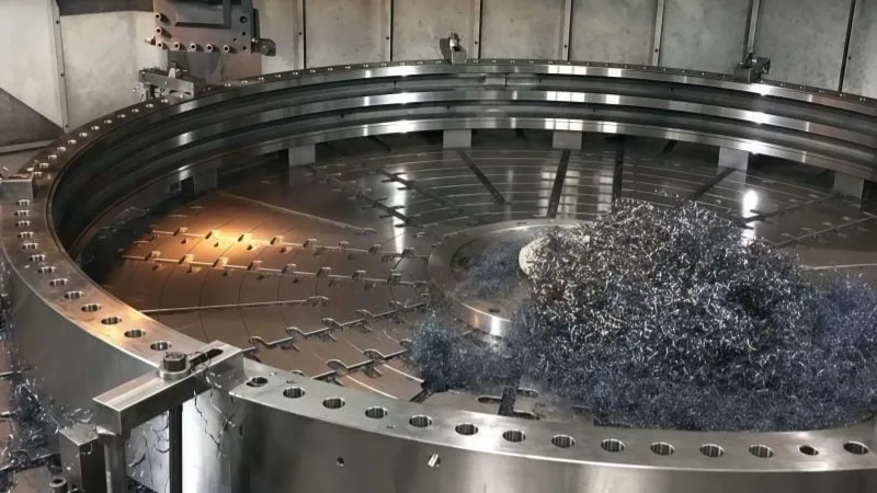
The primary difficulty in hard turning slewing bearing3 raceways lies in the combination of severe interrupted cutting caused by lubrication holes, inconsistent surface hardness due to induction hardening, and large dimensional deformations. These factors create a harsh machining environment where cutting forces fluctuate wildly, causing rapid tool failure and surface defects if not managed correctly.
Impact shock generated by oil holes located in the raceway groove
The most immediate threat to tool life during raceway machining is the presence of lubrication holes and gear teeth interruptions. Unlike continuous cutting, where the tool maintains constant contact with the material, raceway turning involves a series of violent collisions.
Every time the CBN insert passes over an oil hole, the cutting force drops to zero instantly. When the tool re-enters the steel, it experiences a massive mechanical shock. This is not just a vibration; it is a hammer-blow to the cutting edge. In the machining industry, we classify this as “severe interrupted cutting.”
This is mechanically similar to the entrance shock experienced by a milling cutter entering a hardened workpiece, but repeated hundreds of times per minute. Standard ceramic tools often fail here because they lack the fracture toughness4 to survive this cyclic loading. The repetitive impact creates micro-cracks in the insert substrate, eventually leading to catastrophic breakage known as chipping.
Table: Comparison of Cutting Conditions
| Feature | Continuous Turning | Interrupted Raceway Turning |
|---|---|---|
| Tool Contact | 100% Constant | Intermittent (Breaks at oil holes) |
| Force Type | Static / Stable | Dynamic / High Impact |
| Primary Failure | Abrasive Wear | Edge Chipping / Fracture |
| Heat Flow | Constant into chip | Cycling (Heating and Cooling) |
Hardness variability across the induction hardened zones
A slewing bearing raceway is rarely a uniform piece of steel. Manufacturers use induction hardening to heat treat only the contact path of the bearing. This process creates a “hardened case” while leaving the core of the ring tough and soft. However, this process introduces a significant challenge: the “Soft Belt” (also known as the Soft Zone or Slip Zone).
The induction coil that heats the ring cannot form a perfect closed circle. There is always a gap where the heating starts and stops. In this specific zone, the hardness drops significantly.
- Hard Zone: typically HRC 58–63.
- Soft Zone: can drop to HRC 30–45.
As the tool traverses the raceway, it moves from extremely hard steel to relatively soft steel and back again. This variance wreaks havoc on tool wear patterns. CBN inserts are designed to cut hard materials. When they hit soft steel, the chemical reaction changes. The soft material tends to stick to the cutting edge (adhesive wear), causing built-up edge (BUE). When the tool re-enters the hard zone, this built-up material breaks off, taking pieces of the tool coating or substrate with it.
Handling large uneven allowances on the raceway surface
Slewing bearings are massive components with thin walls relative to their diameter. During the heat treatment process, these rings undergo significant thermal stress. This stress causes the ring to warp or deform. A ring that was perfectly round before quenching often comes out oval or slightly twisted.
This distortion creates “uneven allowances” (variable depth of cut). Imagine you program the machine for a 0.5mm cut depth. Because the ring is oval:
- At 0°, the tool might cut 0.5mm (nominal).
- At 90°, the distortion might make the tool cut 1.5mm (heavy load).
- At 180°, the tool might cut air (no load).
This fluctuation is dangerous. A sudden increase in the depth of cut (ap) drastically increases cutting pressure. If the cut becomes too deep, the resistance may exceed the machine’s clamping rigidity. Conversely, if the tool rubs against the surface without cutting (due to low allowance), it generates excessive heat and work-hardens the surface.
The Need for a Specialized Solution
Given these extreme physical demands—impact shock, fluctuating hardness, and uneven loads—Solid Cubic Boron Nitride (CBN) has emerged as the mainstream solution.
Selecting the Optimal CBN Grade and Geometry for Raceways
Which specific CBN insert configuration delivers the highest reliability when machining large, hardened slewing bearing raceways?
For machining slewing bearing raceways, Solid CBN inserts5 in round geometries (RNGN or RCGX) provide the necessary structural integrity and edge strength. Unlike brazed tips, solid CBN can withstand the high thermal loads of deep profiling cuts without delamination. Furthermore, selecting a round shape maximizes edge strength against impact, while a specialized negative chamfer edge preparation is critical for preventing fracture when crossing oil holes.
Advantages of solid CBN structure for deep profiling cuts
In the world of hard turning, engineers must choose between “Brazed (Tipped) CBN” and “Solid CBN.” For slewing bearings, the choice is heavily skewed toward Solid CBN.
A brazed insert consists of a small CBN tip glued (brazed) onto a carbide body. This works well for light finishing. However, slewing bearing raceways often require removing large uneven allowances, sometimes exceeding 2mm in depth.
Thermal Stability Failure in Brazed Tools
When you cut deeply into a large hardened ring, the process generates immense heat. This heat accumulates in the cutting zone. The brazing material that holds a tipped insert together typically has a melting point around 700°C. If the cutting temperature exceeds this limit, the braze joint softens. The CBN tip can detach or shift, leading to immediate tool failure.
The Solid CBN Solution
Solid CBN inserts are made entirely of cubic boron nitride material. There is no joint to fail. This allows the tool to handle much higher temperatures and deeper cuts. You can utilize the entire thickness of the insert if necessary.
Table: Solid CBN vs. Brazed CBN for Raceway Turning
| Feature | Brazed (Tipped) CBN | Solid CBN |
|---|---|---|
| Structure | CBN tip brazed to Carbide | 100% CBN Sintered Body |
| Max Depth of Cut | Limited by tip size (<0.5mm) | Limited only by machine power (>1.5mm) |
| Heat Resistance | Limited by braze joint melting point | Extremely High |
| Impact Resistance | Low (Carbide backing is softer) | High (Uniform hardness) |
| Best Application | Light finishing / Small parts | Heavy Roughing / Large Bearings |
Stability benefits of round RCGX and RNGN shapes for curved tracks
The geometry of the insert defines how forces are distributed. For raceway profiles, Round (R-shape) inserts are the industry standard.
Why Sharp Corners Fail
Consider a standard diamond-shaped insert (CNMG or DNMG) with a defined corner radius (e.g., 0.8mm). When this small corner hits a hard spot or an interruption, all the mechanical stress concentrates on that tiny point. It is like a stress riser. In hardened steel, this point is likely to snap.
The Strength of the Round Shape
A round insert does not have a “weak point.” The cutting forces are distributed over a much wider, curved edge. This geometry offers the highest possible edge strength. When the tool impacts an interruption, the load is spread out, preventing catastrophic breakage.
Comparing RCGX and RNGN
- RCGX (Positive Rake): These are single-sided. They generate lower cutting forces. Use these if your machine is older or if the bearing ring clamping is not perfectly rigid.
- RNGN (Negative Rake): These are double-sided and much stronger. They require more machine power but offer the best economy (more edges) and durability for the heaviest cuts.
Necessary edge preparation to survive interrupted cuts over oil holes
Selecting the right grade and shape is not enough. You must also inspect the microscopic geometry of the cutting edge, known as Edge Preparation.
If a CBN edge is razor-sharp, it is brittle. When it hits an oil hole in the raceway, the edge will chip instantly. To prevent this, manufacturers apply a “Chamfer” or “T-land” (Negative Land).
The Function of the Chamfer
A chamfer is a small angled flat ground onto the cutting edge. It changes the direction of the cutting forces.
- Sharp Edge: Directs force into the shear plane but leaves the edge unsupported.
- Chamfered Edge: Directs the cutting force into the body of the insert. This puts the CBN material under compression rather than tension. CBN is extremely strong in compression but weak in tension.
Recommended Specifications
For heavy interrupted cutting on raceways, a standard light hone is insufficient. You typically need a heavy preparation.
- Angle: 20° to 30° negative angle.
- Width: 0.1mm to 0.2mm width.
This concept is similar to comparing a sharp, positive-rake insert used for finishing aluminum (which would chip instantly on hardened steel) with a negative-rake roughing insert used for cast iron (blunt wedge shape). You need the structural “wedge” support of the chamfer to survive the heavy impact of the oil hole.

Best Practices for Raceway Machining Stability and Tool Life
How can machine operators ensure consistent quality and maximize the lifespan of expensive CBN inserts when turning hardened raceways?
To ensure process stability and extend tool life during raceway machining, operators must prioritize maximum system rigidity to counteract high passive cutting forces. It is critical to employ dry cutting techniques to prevent thermal shock in the CBN substrate and to actively monitor specific wear patterns, replacing inserts before flank wear exceeds 0.3mm to maintain dimensional accuracy.
Maximizing clamping rigidity to handle heavy cutting forces
When turning hardened slewing bearing raceways (HRC 58-63), the physics of cutting change dramatically compared to soft steel. The most significant change is the increase in passive force (radial force).
In standard turning, the cutting force primarily pushes down. In hard turning, the tool pushes heavily “back” against the workpiece. Because slewing rings are often large in diameter but have relatively thin walls, they act like large springs. If the clamping is weak, the ring will vibrate or deform under this pressure.
Clamping Solutions
To stop this, you must secure the ring effectively.
- Use Pie Jaws (Full-Grip Jaws): Standard 3-jaw chucks are insufficient. They distort the ring into a triangle shape. Pie jaws cover a larger surface area, distributing the pressure evenly.
- Vertical Lathe Support: For large rings, gravity helps hold the part flat on a vertical lathe table, providing better stability than a horizontal setup.
- Hydraulic Pressure: Ensure hydraulic pressure is high enough to hold the part but low enough to prevent distorting the raceway geometry.
Avoiding thermal shock in the hardened zone through dry cutting
A common mistake in raceway machining is the use of coolant. For CBN turning, specifically on interrupted raceways, you should almost always use Dry Cutting.
The Mechanism of Thermal Shock
Turning hardened steel generates intense heat at the cutting point, often exceeding 800°C. This heat is actually beneficial. It softens the steel directly in front of the tool tip (a process called plasticization), making it easier to cut.
If you spray coolant on this super-heated zone, the temperature drops instantly. However, as the tool rotates and cuts the next section, it heats up again. This rapid cycle of heating and cooling (thousands of times per minute) creates thermal cracks in the insert.
The Effect on Interrupted Cuts
This is even more critical when machining raceways with oil holes.
- Cut: The tool is hot.
- Hole: The tool exits the cut and cools down slightly.
- Re-entry: The tool hits the steel and heats up instantly.
Adding coolant exaggerates this temperature swing. It causes the CBN binder to fail, leading to “thermal shock breakage.”
Monitoring flank and crater wear specific to high-speed turning
You cannot run CBN inserts until they break. You must monitor wear patterns to predict when to change the edge. In raceway machining, two specific types of wear tell you the story of your process stability.
Flank Wear (VB)
This is the abrasive wear on the side of the tool. As the flank wears flat, the contact area increases.
- The Consequence: A larger wear flat pushes harder against the raceway. This increases the passive force, which pushes the bearing ring away.
- The Result: You lose dimensional accuracy. The raceway diameter will be incorrect.
- The Limit: Generally, you should index (rotate) the insert when flank wear reaches 0.2mm to 0.3mm. Going beyond this risks sudden breakage.
Crater Wear (KT)
This is a hollow depression on the top face of the insert, caused by hot chips sliding over it.
- The Consequence: The crater weakens the cutting edge structure.
- The Cause: Often caused by cutting speeds that are too high for the specific grade of CBN.
Table: Troubleshooting CBN Wear on Raceways
| Wear Type | Visual Appearance | Cause | Corrective Action |
|---|---|---|---|
| Flank Wear | Flat shiny area on side | Normal abrasion | Change tool at 0.3mm wear. |
| Chipping | Small pieces missing | Vibration or Impact | Increase rigidity; Check edge prep. |
| Crater Wear | Pit on top surface | High Temperature | Reduce cutting speed. |
| Thermal Cracks | Vertical cracks on edge | Thermal Cycling | Turn off coolant (run dry). |
Raceway Machining Case Studies and Recommended Parameters
To illustrate the effectiveness of the strategies discussed above, we can look at real-world production data. The following case studies and parameter tables provide a verified baseline for manufacturers looking to optimize their slewing bearing production.
Field applications confirm that machining induction hardened raceways with Solid CBN inserts can achieve grinding-level surface finishes of Ra 0.4 μm while reducing cycle time by up to 70% compared to traditional grinding. Successful operations typically utilize cutting speeds between 80 and 180 m/min, with feed rates adjusted between 0.1 and 0.5 mm/rev depending on the severity of the interrupted cut.
Wind turbine pitch bearing raceway results on HRC 58-62
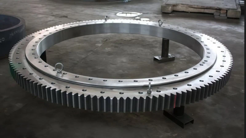
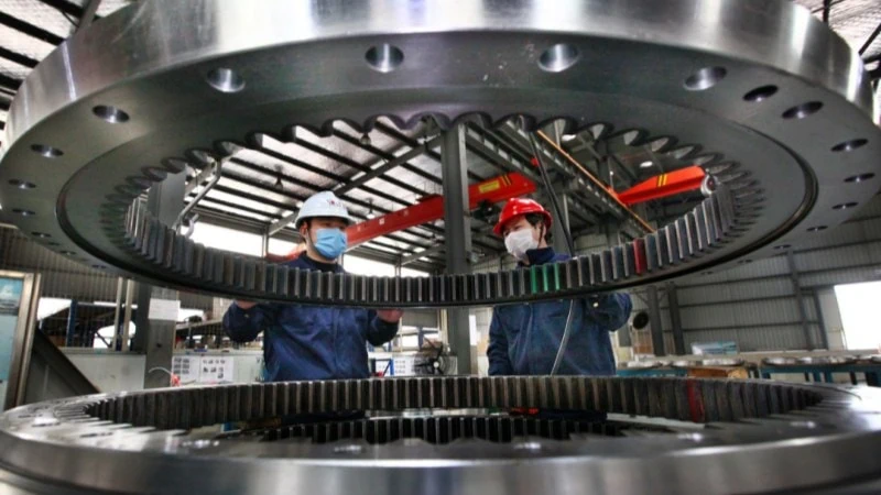
Wind turbine pitch bearings represent the upper limit of precision in heavy industry. These bearings are massive, often exceeding 2 meters in diameter. The raceway surface must be incredibly smooth because any imperfection can lead to bearing failure 100 meters up in the air.
In a specific case involving a leading energy equipment manufacturer, the goal was to replace a slow grinding process with hard turning. The workpiece was a Pitch Bearing Outer Ring made of 42CrMo steel, induction hardened to HRC 58-62.
The Challenge:
The previous grinding process took approximately 180 minutes per ring. The manufacturer needed to increase output without buying more grinding machines.
The Solution:
They implemented a Solid CBN insert (RNGN 120400). The round shape provided a strong edge, and the high thermal conductivity of the solid CBN prevented heat build-up in the large contact area.
The Results:
The switch to hard turning transformed the production line.
- Cycle Time: Reduced from 180 minutes to 45 minutes.
- Surface Finish: Achieved Ra 0.4 μm, which matches the quality of the ground surface.
- Process Reliability: One insert edge completed the full raceway cut without requiring mid-process indexing or compensation, ensuring a continuous surface finish.
This case proves that for large continuous cuts, CBN turning is not just a roughing operation; it is a viable finishing strategy.
Construction machinery slewing ring solutions for heavy interruptions
Excavator and crane slewing rings present a different problem. While they are slightly smaller than wind turbine bearings, they are much more abusive to the tool. This is because these raceways frequently contain oil lubrication holes and sometimes intersect with gear features.
A manufacturer of excavator parts faced a critical issue with 50Mn steel rings (HRC 55-60). Every time their cutting tool passed over the 10mm oil hole in the raceway, the ceramic insert they were using would shatter.
The Technical Adjustment:
The solution required prioritizing toughness over pure speed. They switched to a Solid CBN grade with a high cubic boron nitride content (approx. 90%) and a heavy edge preparation.
- Edge Prep: 0.2mm x 20° negative chamfer.
This geometry acts like a shock absorber. When the tool hits the gap of the oil hole, the negative angle directs the impact force into the center of the insert rather than snapping the sharp edge.
Performance Data:
- Impact Resistance: The tool survived over 2,000 impacts (crossing the hole) without chipping.
- Stability: The operator could run the machine unattended, as the risk of sudden breakage was eliminated.
Specific reference data for cutting speed, feed rate, and depth of cut
Setting the correct parameters is the difference between a profitable job and a scrap part. While the cutting speed (Vc) is generally independent of size, the machine rigidity and wall thickness of large-diameter rings play a crucial role in determining the maximum safe depth of cut.
Table: Recommended Cutting Parameters for Raceway Turning (Solid CBN)
| Cutting Condition | Cutting Speed (Vc) | Feed Rate (f) | Depth of Cut (ap) |
|---|---|---|---|
| Continuous Cut (No holes, smooth) | 120 – 180 m/min | 0.2 – 0.5 mm/rev | 0.2 – 1.5 mm |
| Light Interruption (Small oil holes) | 100 – 150 m/min | 0.15 – 0.3 mm/rev | 0.2 – 1.0 mm |
| Heavy Interruption (Large holes/Gear teeth) | 70 – 110 m/min | 0.1 – 0.2 mm/rev | 0.1 – 0.5 mm |
Engineering Notes for Parameter Optimization:
- Surface Finish: To achieve Ra 0.4 μm with a standard RNGN1204 round insert, maintain the feed rate (f) between 0.15 and 0.25 mm/rev. Feed rates above 0.3 mm/rev are typically used for roughing or semi-finishing.
- Impact Management: As interruptions become more severe, Cutting Speed (Vc) must be reduced. High speed generates high impact energy; reducing speed to 70-110 m/min significantly lowers the shock load on the cutting edge.
- Dimensional Constraint (Rigidity): For large-diameter slewing rings with thin walls (low radial rigidity), avoid aggressive depths of cut (ap > 0.5mm). High depth of cut generates excessive radial force, which can cause vibration (chatter) and ovality deformation, regardless of the tool’s capability.
Conclusion
The transition from traditional grinding to hard turning with Solid CBN inserts offers slewing bearing manufacturers a clear path to increased efficiency and reduced production costs. While challenges such as interrupted cutting over oil holes, hardness variability in induction zones, and uneven allowances are significant, they are manageable with the correct technical approach.
By selecting robust round inserts (RNGN/RCGX), applying specific negative edge preparations, and adhering to strict dry cutting protocols, operators can achieve high-precision results that meet the rigorous demands of the wind power and construction industries. As demonstrated in the case studies, mastering these variables transforms a difficult machining task into a predictable, high-speed operation.
References
- Hard Turning1 – ZYDiamondTools article explaining the hard turning process and comparing it to grinding.
- Interrupted Cutting2 – ZYDiamondTools guide on solutions for interrupted cuts using PCBN tools.
- Slewing Bearing3 – Wikipedia entry defining the structure and application of slewing bearings.
- Fracture Toughness4 – Wikipedia article explaining the concept of fracture toughness in materials.
- Solid CBN Inserts5 – Product page for Solid CBN inserts designed for heavy-duty machining applications.


