-
Whatsapp: +86 13526572721
-
Email: info@zydiamondtools.com
-
Address: AUX Industrial Park, Zhengzhou City, Henan Province, China
-
Whatsapp: +86 13526572721
-
Email: info@zydiamondtools.com
-
Address: AUX Industrial Park, Zhengzhou City, Henan Province, China

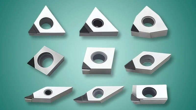
Which Turning Insert Shape Should You Choose?

So, what is the secret to selecting the perfect turning insert shape for any job?
Choosing the right turning insert shape involves a three-part process: First, match the shape’s strength and versatility to your specific machining job and material. Second, learn to read the ISO code to correctly identify the insert’s features. Finally, fine-tune your selection by choosing the correct nose radius and insert size for optimal performance.
This guide will walk you through each of these stages, transforming a complex decision into a clear, step-by-step process that will help you improve cutting performance and efficiency.
How Do I Match an Insert Shape to My Machining Job?
So, how do you correctly pair a turning insert’s shape with your specific machining task?
To match an insert shape to your job, you must first balance the strength required for roughing against the versatility needed for finishing. Next, analyze your toolpath for clearance requirements. Finally, select a shape compatible with your material’s machinability.
This three-step process ensures you choose an insert that is not only strong enough for the task but also capable of creating the precise geometry your part requires, leading to better performance and longer tool life.
Step 1: Balancing Strength for Roughing vs. Versatility for Finishing
The first decision comes down to a fundamental trade-off: strength versus flexibility. The shape of an insert is defined by its corner angle, also known as the nose angle. This angle directly determines how strong the cutting edge is.
Think of it like the tip of a pencil. A very sharp, pointed tip can draw fine, detailed lines but breaks easily under pressure. A dull, rounded tip is much stronger but can’t create those same details. The same principle applies to turning inserts.
- A larger nose angle (like on a round or square insert) creates a stronger cutting edge. This strength allows it to handle higher feed rates and deeper cuts, making it ideal for roughing operations where the goal is to remove a lot of material quickly.
- A smaller nose angle (like on a triangle or 35° diamond insert) creates a sharper, more pointed cutting edge. While this edge is weaker, it provides the versatility needed to machine complex profiles, sharp corners, and fine details in finishing operations.
This relationship is one of the most critical factors in turning. As a general rule, always select the largest possible nose angle that your job will allow to maximize strength and tool life.
| Characteristic | Roughing Inserts (Large Nose Angle) | Finishing Inserts (Small Nose Angle) |
|---|---|---|
| Primary Goal | High Material Removal Rate (MRR) | High Surface Finish & Accuracy |
| Strength | Very High | Lower |
| Feed Rate | High | Low |
| Versatility | Low (Cannot machine complex profiles) | High (Excellent for profiling) |
| Common Shapes | Round (R), Square (S), Trigon (W), 80° Diamond (C) | 55° Diamond (D), 35° Diamond (V), Triangle (T) |
Step 2: Assessing Your Toolpath and Clearance Needs
After you determine the strength you need, you must consider the physical path the tool will take. Can the insert reach every surface it needs to cut without the tool holder or the back of the insert colliding with the workpiece? This is a question of clearance.
An insert’s shape dictates its ability to perform different types of cuts. For example, a square insert (S) is extremely strong but can only perform straight turning and facing operations. If your part has shoulders, tapers, or contoured surfaces, a square insert is simply not an option.
Profiling and Undercutting Applications
For parts with complex geometries, you need an insert with a smaller, more acute nose angle. A 55° diamond insert (D), for instance, provides excellent clearance and is a popular choice for copy turning and profiling. For even tighter spaces or more intricate details, a 35° diamond insert (V) offers maximum accessibility, allowing you to machine sharp angles and undercuts that other shapes cannot reach.
Industry Case Study: A manufacturer producing hydraulic fittings needed to machine a part with a tight internal groove and a tapered face. An 80° CNMG insert, used for the initial roughing, could not access the groove without the tool holder interfering. By switching to a 55° DNMG insert for the finishing pass, the operator could successfully trace the entire profile, achieving the required geometry and surface finish in a single operation.
Step 3: Considering Your Material’s Machinability
Finally, the material you are cutting plays a huge role in your selection. Different materials exert different levels of force and temperature on the cutting edge, requiring specific insert characteristics.
Hardened Steels and Superalloys
Materials like Inconel, titanium, and hardened steels (>45 HRC) are difficult to machine. They generate extreme heat and cutting pressure, which can easily chip or break a weak cutting edge. For these applications, strength is the top priority.
- Recommendation: Use the strongest shapes possible, such as Round (R) or Square (S) inserts. These shapes distribute the cutting force and heat over a larger area, protecting the cutting edge and extending tool life.
General Purpose Steels and Cast Irons
Carbon steels, alloy steels, and cast irons1 are the most common materials in machining. They offer a good balance of machinability and durability.
- Recommendation: The 80° diamond (C) is often considered the workhorse for these materials, providing an excellent blend of strength for medium roughing and versatility for general-purpose turning. For more profiling-intensive jobs, the 55° diamond (D) is a reliable choice.
Aluminum and Non-Ferrous Metals
Materials like aluminum and brass are soft and machine easily. The main challenge here is not strength but preventing built-up edge (BUE)2, where material welds itself to the insert.
- Recommendation: Sharp, pointed inserts like the Triangle (T) shape are highly effective. They have a more positive cutting action that cleanly shears the material and directs chips away from the workpiece.
Because machinability ratings and performance can differ based on the exact material grade, it’s always a good practice to verify specific geometry and grade recommendations with your tooling supplier to ensure optimal results.
How Do I Read ISO Codes to Identify the Shape?
Have you ever wondered what the long string of letters and numbers on a turning insert actually means?
To read an ISO insert code, you decode it position by position. The first letter identifies the insert’s shape, the second letter specifies the clearance angle, and the fourth letter typically describes the chipbreaker geometry and hole type.
This standardized system, established by the International Organization for Standardization (ISO), acts like a universal language for machinists. Once you understand the basics, you can quickly identify the key features of an insert just by looking at its name, no matter who the manufacturer is.
The First Letter: Shape (C, D, T, W)
The very first letter of the code is arguably the most important, as it tells you the fundamental shape of the insert. This letter corresponds to a specific geometry and nose angle, which, as we discussed earlier, determines the insert’s strength and application range.
Think of this letter as the foundation of the insert’s identity. Each one represents a distinct profile.
| Letter | Shape Name | Nose Angle |
|---|---|---|
| C | 80° Diamond (Rhombic) | 80° |
| D | 55° Diamond (Rhombic) | 55° |
| R | Round | N/A |
| S | Square | 90° |
| T | Triangle | 60° |
| V | 35° Diamond (Rhombic) | 35° |
| W | Trigon | 80° |
For example, if you have an insert named CNMG 432, that first letter “C” immediately tells you it is an 80° diamond shape, making it a strong and versatile choice for general turning.
The Second Letter: Clearance Angle
The second letter defines the insert’s clearance angle (also known as the relief angle). This is the angle between the flank of the insert and the surface of the workpiece. Proper clearance is essential to prevent the tool from rubbing, which causes friction, high temperatures, and poor surface finish.
This letter also tells you a critical piece of information: whether the insert is negative or positive.
- Negative Inserts (e.g., ‘N’ for 0° clearance): These inserts are flat on the top and bottom, meaning they have no built-in clearance. The clearance is created by tilting the insert in the tool holder. Because they are flat on both sides, you can flip them over and use the cutting edges on the back, effectively doubling the number of available edges. This makes them stronger and more economical for roughing.
- Positive Inserts (e.g., ‘C’ for 7°, ‘P’ for 11°): These inserts have a built-in clearance angle. This design reduces cutting forces, making them ideal for finishing passes, machining slender parts, and cutting soft, “gummy” materials. However, they are only single-sided.
Using our example CNMG 432, the “N” tells us it is a negative insert with 0° clearance. This means it’s a strong, double-sided insert designed for higher feed rates.
The Fourth Letter: Chipbreaker Geometry
While the third letter denotes the tolerance class (a measure of the insert’s dimensional accuracy), the fourth letter is far more critical for day-to-day performance. It describes the physical design of the insert’s top surface—specifically its hole type and chipbreaker.
What is a chipbreaker3? It’s a complex landscape of grooves, bumps, and channels molded into the top of the insert. Its job is to curl and break the long, stringy chips produced during turning into smaller, more manageable pieces. Proper chip control is crucial for safety and for preventing damage to the part’s surface finish.
The fourth letter tells you about the general style. For example:
- G: Indicates a through-hole with a chipbreaker on both faces.
- M: Indicates a through-hole with a chipbreaker on one face.
- A: No hole, with a chipbreaker on one face.
- N: No hole and no chipbreaker (a flat-top insert).
In our example CNMG 432, the “G” tells us this insert has a hole for locking it in place and has a chipbreaker on both of its usable sides.
Important Note on Chipbreakers: The fourth letter provides a basic classification. However, the specific design of the chipbreaker—optimized for finishing, roughing, or a certain material—is usually designated by a two-letter code at the end of the sequence (e.g., CNMG 432-PM). These final codes are highly manufacturer-specific. A “-PM” from one brand may not be the same as a “-PM” from another. Always consult your tooling manufacturer’s catalog to decode these specific chipbreaker styles and find the right one for your material and application.
What Other Critical Features Affect Performance?
Beyond the main shape, what other insert features have a major impact on your turning performance?
Beyond the primary shape, the two most critical features affecting performance are the nose radius, which dictates surface finish and edge strength, and the insert size (IC), which determines its ability to handle deep cuts and high forces.
Selecting the right shape gets you halfway there, but mastering these two final details is the key to truly optimizing your process for efficiency, quality, and tool life. They are the fine-tuning knobs that turn a good setup into a great one.
Selecting the Correct Nose Radius
The nose radius is the size of the small, rounded corner that forms the cutting point of the insert. It might seem like a tiny detail, but its impact on your machining is enormous. The choice involves a trade-off between strength and cutting pressure.
- A larger nose radius creates a stronger cutting edge. It spreads the cutting force and heat over a wider section of the insert. This allows for much higher feed rates while producing an excellent surface finish. However, this wider contact area also increases radial pressure, which can lead to vibration, especially on slender or unstable parts.
- A smaller nose radius is weaker and has a more focused point of contact. It is ideal for finishing at low feed rates and is necessary for machining fine details and sharp corners. Because it exerts less pressure on the workpiece, it is the preferred choice for preventing vibration on thin components.
Nose Radius and the ISO Code
You can identify the nose radius from the last digit in a standard inch insert code. For example, in the code CNMG 432:
- The final digit, 2, represents the nose radius in 64ths of an inch.
- So, a “2” means a radius of 2/64″, which simplifies to 1/32″ (or 0.0313 inches).
- A “1” would mean 1/64″ (0.0156″), and a “3” would mean 3/64″ (0.0469″).
A Key Machining Principle: For a good surface finish, a common rule of thumb is to set your feed per revolution to be less than half of the nose radius. For a CNMG 432 insert (0.0313″ radius), you would typically aim for a feed rate below 0.015 inches per revolution (IPR) during finishing.
| Characteristic | Small Nose Radius (e.g., 1/64″) | Large Nose Radius (e.g., 3/64″) |
|---|---|---|
| Edge Strength | Lower | Higher |
| Surface Finish | Good at low feed rates | Excellent at high feed rates |
| Vibration Risk | Low | High |
| Ideal Application | Finishing, profiling, unstable parts | Roughing, stable parts, high-feed turning |
Choosing the Right Insert Size (IC)
The final critical feature is the overall size of the insert, which is standardized by its Inscribed Circle (IC). The IC is the diameter of the largest circle that can be drawn entirely within the boundaries of the insert shape. Simply put, a larger IC means a bigger and more robust insert.
The choice of IC is almost exclusively driven by one factor: your planned depth of cut.
Imagine trying to chop down a large tree. You wouldn’t use a small hand axe; you’d use a large, heavy felling axe. The same logic applies here. Heavy-duty jobs with deep cuts require large inserts that can absorb the immense cutting forces and effectively dissipate heat. Using an insert that is too small for a deep cut is a primary cause of catastrophic tool failure.
Finding the IC in the ISO Code
In an inch insert code, the IC is typically indicated by the number immediately following the shape letter. For example, in the code CNMG 432:
- The number 4 indicates the IC in eighths of an inch.
- This means the insert has an IC of 4/8″, or 1/2 inch.
- A “3” would indicate 3/8″ IC, and a “5” would indicate 5/8″ IC.
It is crucial that the IC of the insert matches the designated pocket size of your tool holder. You cannot fit a 1/2″ IC insert into a tool holder designed for 3/8″ inserts. Always ensure your insert and holder are compatible before setting up a job.
Conclusion
Selecting the right turning insert is not about finding a single ‘magic’ shape, but about following a logical process. By first understanding the demands of your job—balancing roughing and finishing, toolpath, and material—you can narrow down your options. Next, using the ISO code as your guide, you can confidently identify the exact geometry you need. Finally, by paying attention to critical details like nose radius and insert size, you can optimize the entire process for peak performance, better surface finishes, and longer tool life. This systematic approach transforms insert selection from a challenge into a strategic advantage.
References
- cast irons1 – A detailed guide from ZYDiamondTools on the specific techniques for machining hard cast iron using PCBN tools.
- built-up edge (BUE)2 – A Wikipedia article defining and explaining the formation of built-up edge, a common phenomenon in metal cutting.
- chipbreaker3 – A ZYDiamondTools guide explaining how to select and apply chipbreaker inserts for optimal machining performance.