-
Whatsapp: +86 13526572721
-
Email: info@zydiamondtools.com
-
Address: AUX Industrial Park, Zhengzhou City, Henan Province, China
-
Whatsapp: +86 13526572721
-
Email: info@zydiamondtools.com
-
Address: AUX Industrial Park, Zhengzhou City, Henan Province, China

What Are the Best Cutting Tools for Camshaft Machining? A Complete Guide
What does it take to choose and use the best cutting tools for manufacturing a high-precision camshaft?
Achieving a perfectly machined camshaft requires understanding the primary operations (milling, turning, and grinding), selecting the right tools for each stage (from carbide for roughing to PCBN for finishing), choosing the correct tool material and geometry for the specific camshaft alloy, and finally, optimizing performance by managing speeds, feeds, tool wear, and coolant.
What Are the Primary Camshaft Machining Operations?
So, what exactly are the key steps that transform a simple metal bar into a highly precise camshaft?
Camshaft machining is a multi-stage manufacturing process that turns a metal blank into a finished component through a specific sequence of operations. The primary operations include lobe profile milling or turning to create the unique cam shapes, machining the main and pin journals to ensure a precise rotational fit, and finally, grinding or superfinishing to achieve the exact surface finish and tight tolerances required for engine performance.
Think of creating a camshaft like a sculptor creating a detailed statue from a block of stone. It’s not a single action but a series of deliberate steps, each one refining the component further. First, the sculptor carves the rough, overall shape. Then, they refine the smaller details. Finally, they polish the surface to a perfect shine. Camshaft machining follows this same fundamental logic, moving from rough shaping to ultra-fine finishing.
Lobe Profile Milling and Turning
The heart of the camshaft is the lobe—the “egg-shaped” bumps that push open the engine valves. Creating this precise shape is the most critical and defining operation. This is where the camshaft gets its unique character, as the lobe’s profile dictates the engine’s timing and performance.
So, how are these essential shapes formed? There are two primary methods.
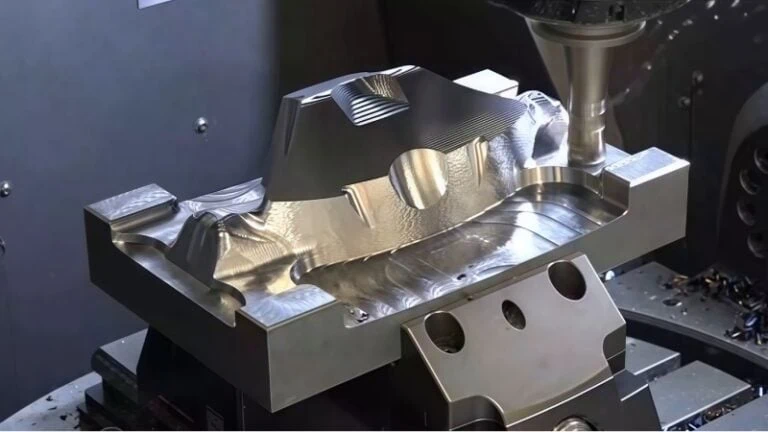
Lobe Profile Milling
In milling, the camshaft blank is held firmly in place while a rotating cutting tool, much like a high-tech drill bit, moves around it. This cutter carefully carves away material to form the complex, non-symmetrical shape of the lobe. This method offers excellent flexibility and is often used for high-performance or prototype camshafts with unique profiles. The process must be incredibly precise, as even a tiny error in the lobe’s shape can drastically affect engine efficiency.
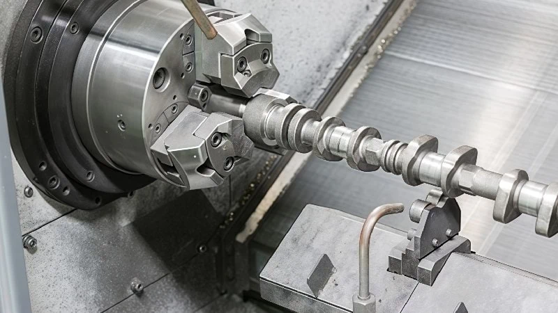
Lobe Profile Turning
In turning, the roles are reversed. The camshaft blank rotates, and a stationary cutting tool is brought into contact with it. As the camshaft spins, the tool carefully shaves off material to generate the lobe shape. This is an efficient process, particularly for mass production of camshafts with more conventional designs.
Machining Main Journals and Pin Journals
After the lobes are formed, the next crucial step is machining the journals. What are journals? They are the perfectly round, smooth sections of the shaft that rest inside the engine block on bearings.
Imagine the journals as the axles for a set of wheels. If the axle isn’t perfectly round and smooth, the wheel won’t spin correctly. It’s the same for a camshaft. These surfaces must be machined to an exact diameter with a very smooth finish to allow the camshaft to rotate thousands of times per minute with minimal friction and wear. This operation is typically done on a lathe, ensuring the journals are perfectly concentric (aligned with the central axis of the shaft).
Grinding and Superfinishing for Final Tolerances
This is the final and most precise stage, where the camshaft is taken from a well-shaped component to a piece of high-precision engineering. After the initial milling and turning, the camshaft is often heat-treated to make it extremely hard and durable. However, this hardening process can cause microscopic distortions.
Grinding corrects these tiny imperfections. The process uses a rapidly spinning abrasive wheel to remove minuscule amounts of material—often just a few microns (µm) at a time (a human hair is about 70 microns thick).
The goal here is two-fold:
- Achieve Final Tolerance: Ensure every dimension is perfect, often within a tolerance of less than 10 µm.
- Create a Superior Surface Finish: Produce a near-mirror finish on the lobes and journals. Surface finish is measured in Ra (Roughness Average)1, and for high-performance camshafts, a target of Ra 0.2 is common. A smoother surface drastically reduces friction and extends the life of the engine.
Because these final specifications are so critical and can differ based on engine design, it’s always wise to confirm the exact tolerance and surface finish requirements directly from the engineering blueprints or component supplier. This ensures the final product meets the necessary performance standards.

Which Cutting Tools Excel in Each Machining Stage?
Now that we know the different stages, which specific tools are used for each job to ensure the best results?
The key to efficient camshaft machining is assigning specific tools to each stage based on their unique strengths. Generally, durable indexable carbide mills are used for the initial roughing and semi-finishing. For the final, high-precision work on hardened surfaces, ultra-hard PCBN or CBN inserts are required. Finally, specialized vitrified grinding wheels perform the critical finishing to meet strict tolerance and surface standards.
Choosing the right tool is like a chef choosing the right knife. A butcher knife is perfect for heavy-duty chopping, while a small paring knife is needed for fine, detailed work. Using the wrong tool for the job leads to poor results, wasted time, and high costs. In machining, this principle is even more critical, as each tool is engineered for a very specific task.
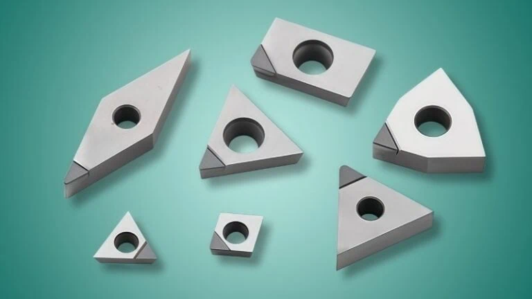
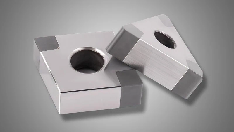
PCBN & CBN Inserts for Hard Machining and Finishing
After a camshaft is hardened, it becomes extremely resistant to cutting. This is where PCBN (Polycrystalline Cubic Boron Nitride) and CBN (Cubic Boron Nitride) inserts2 are essential. These are synthetic materials with a hardness second only to diamond, allowing them to slice cleanly through hardened steel and cast iron (typically materials harder than 45 HRC).
Think of these inserts as the fine-tipped chisel used for the final, defining details. Their primary job is not to remove a lot of material, but to perform the final precision pass.
- Why they excel: Their incredible hardness means they maintain a sharp cutting edge for a long time, even when machining abrasive, hardened materials. This wear resistance is crucial for holding the tight tolerances required for camshaft lobes and journals.
- Industry Application: In a typical automotive production line, after a camshaft is hardened to over 60 HRC, PCBN inserts are used for the final finishing operation. This process, known as hard machining, uses the inserts to remove just the last 0.2 mm to 0.5 mm of material. This single, precise pass can be done through either hard turning (where the camshaft rotates against a stationary PCBN insert) or hard milling (where a rotating milling cutter with PCBN tips moves across the camshaft). Both methods establish the final, precise shape and a very smooth surface.
Indexable Carbide Mills for Roughing and Semi-Finishing
Before the camshaft is hardened, it’s in a much softer state. The main goal during this initial stage is to remove a large volume of material quickly and efficiently. This is the job for indexable carbide mills.
These tools are the workhorses of the machining world. “Carbide” refers to Tungsten Carbide, a very tough and heat-resistant material. “Indexable” means the tool uses small, replaceable carbide inserts as its cutting edges. When an edge gets dull, you don’t replace the whole tool; you simply rotate or “index” the insert to a fresh edge, saving time and money.
- Why they excel: Their main advantage is toughness. They can withstand the heavy forces and vibrations of deep cuts and high feed rates without chipping or breaking. This makes them ideal for quickly carving the basic shape of the camshaft from a solid metal blank.
- Case Study: Consider a forged steel camshaft blank. A large-diameter indexable mill might be used to machine the main journals, removing several millimeters of material in a single pass. The goal is efficiency, and carbide tools allow for the highest possible Material Removal Rates (MRR).
To make the distinction clear, here is a simple comparison:
| Feature | Indexable Carbide Mills | PCBN & CBN Inserts |
|---|---|---|
| Primary Stage | Roughing & Semi-Finishing | Finishing & Hard Machining |
| Workpiece Hardness | Softer (Below 45 HRC) | Very Hard (Above 45 HRC) |
| Key Advantage | Toughness, High Removal Rate | Hardness, Precision Finish |
| Primary Goal | Efficiently create the basic shape | Achieve final dimensions and smoothness |
Custom Profile and Groove Tools for Specialized Features
A camshaft is more than just lobes and journals. It often includes other important features like oil grooves, sensor rings, or specific chamfers. These features require tools that are custom-made for a single, specific purpose.
Imagine trying to carve a thin, spiral groove with a standard, flat chisel. It wouldn’t work well. You’d need a special tool with a tip shaped exactly like the groove you want to create. Custom profile tools operate on the same principle. These tools are designed and ground to match the exact shape of the feature they are cutting, ensuring a perfect result in a single pass. For example, a “grooving tool” is used to cut the channels that distribute oil along the camshaft.
Vitrified Grinding Wheels for Precision Finishing
Finally, for the ultimate level of precision and surface smoothness, we turn to grinding wheels. Specifically, vitrified bond grinding wheels3 are a top choice for camshaft finishing.
A grinding wheel is made of millions of tiny, hard abrasive grains held together by a bonding material. A “vitrified” bond is essentially a glass-like substance that creates a strong but porous structure.
- Why they excel: The porosity of a vitrified wheel is its secret weapon. The tiny open spaces between the grains do two things:
- They carry coolant directly to the cutting zone, preventing heat buildup.
- They provide space for the tiny metal chips to be carried away, preventing the wheel from getting clogged.
This results in a very clean, cool cutting action that produces an exceptionally smooth, mirror-like surface finish. This is the tool that delivers the final Ra values and micron-level accuracy that define a high-quality camshaft.
How Do You Select the Right Tool Material and Geometry?
Knowing which general tool to use is one thing, but how do you choose the perfect version of that tool for your specific job?
Selecting the right tool involves a three-step evaluation. First, you must match the cutting tool’s base material (like carbide or PCBN) to the camshaft’s material, such as cast iron or forged steel. Second, you need to understand the tool’s geometry—primarily its rake and clearance angles—to ensure efficient cutting. Finally, you choose a specific coating, like PVD or CVD, to enhance the tool’s performance and extend its life.
Making the right choice here is the difference between a smooth, efficient operation and a process plagued by broken tools and poor-quality parts. It’s about looking beyond the tool’s name and understanding its fundamental design. Let’s break down these three key selection criteria.
Matching Tool Material to Camshaft Material (Cast Iron vs. Forged Steel)
The first and most important decision is to match your cutting tool to the material you are cutting. Camshafts are typically made from two common materials: chilled cast iron4 and forged steel. Each behaves very differently during machining.
- Chilled Cast Iron: Often used in heavy-duty diesel engines, this material is extremely hard and abrasive. It contains hard graphite particles that act like sandpaper against the cutting tool, causing rapid wear.
- Forged Steel: Common in high-performance gasoline engines, this material is tougher and “gummier” than cast iron. It requires a cutting tool that is both strong and sharp to shear the material cleanly without it building up on the tool edge.
Here’s how you match the tool to the material:
| Camshaft Material | Key Machining Challenge | Recommended Tool Property |
|---|---|---|
| Chilled Cast Iron | Highly Abrasive, causes rapid tool wear. | High Wear Resistance. This is why PCBN, with its exceptional hardness, is the top choice for finishing cast iron. |
| Forged Steel | Tough and prone to built-up edge. | High Toughness & Sharp Edge. Coated carbide inserts with a sharp geometry are ideal for roughing and semi-finishing steel. |
Choosing a tough carbide tool to finish abrasive cast iron would lead to the tool dulling almost instantly. Conversely, using a brittle PCBN tool for heavy roughing on tough steel could cause the cutting edge to chip.
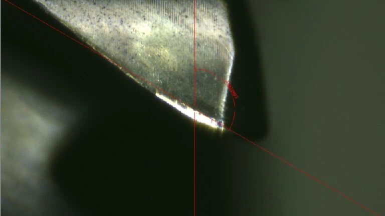
Understanding Critical Geometries: Rake and Clearance Angles
Once you’ve chosen the base material, the next step is to look at the tool’s shape, or its geometry. Two of the most important angles are the rake angle and the clearance angle.
Imagine a simple snowplow. The angle of the blade determines how it moves the snow. A cutting tool’s geometry works in a similar way.
The Rake Angle
The rake angle is the angle of the cutting face. It controls how the metal chip flows off the workpiece.
- A positive rake angle (the cutting face leans back) reduces cutting forces, creates less heat, and is ideal for softer materials like steel. It “shears” the metal cleanly.
- A negative rake angle (the cutting face leans forward) creates a much stronger cutting edge. This is often used with very hard but brittle materials like PCBN to give the edge the strength it needs to cut hardened materials without fracturing.
The Clearance Angle
The clearance angle is the small angle ground below the cutting edge. Its job is simple but critical: to prevent the tool from rubbing against the freshly cut surface. Too little clearance causes friction and heat, damaging both the tool and the part. Too much clearance weakens the cutting edge. It’s a precise balancing act.
The Role of PVD/CVD Coatings for Tool Life and Performance
Finally, consider the tool’s coating. A coating5 is an ultra-thin (often just a few microns) layer of advanced material applied to the tool’s surface. Think of it like the non-stick coating on a high-quality frying pan. It’s a performance multiplier.
A coating’s main jobs are to:
- Increase Hardness: Protect the cutting edge from wear.
- Reduce Friction: Help chips slide off easily, preventing built-up edge.
- Provide a Thermal Barrier: Protect the carbide or PCBN underneath from extreme heat.
There are two common types of coatings, PVD and CVD:
- PVD (Physical Vapor Deposition): This is a lower-temperature process that results in a very thin, smooth, and sharp coating. It’s excellent for carbide tools used on gummy materials like steel because its sharpness prevents material buildup.
- CVD (Chemical Vapor Deposition): This is a higher-temperature process that creates a thicker, more wear-resistant coating. It’s often used for tools machining abrasive cast iron.
The world of coatings is constantly evolving, with new multi-layer options like AlTiN (Aluminum Titanium Nitride) offering superior heat resistance for high-speed machining. For this reason, it is highly recommended to consult your tooling supplier’s latest catalog to choose the optimal coating for your specific application, as they can provide performance data for your exact material and machine setup.

How Can You Optimize Tool Performance and Troubleshoot Common Issues?
Once you’ve selected the perfect tool, how do you ensure you get the best performance from it and solve problems when they arise?
Optimizing tool performance requires a systematic approach. It starts with calculating the correct speeds and feeds for your specific material and tool. Next, it involves actively identifying and preventing common types of tool wear to maximize its life. Finally, proper management of coolant and efficient chip evacuation is essential to maintain a stable and predictable cutting process.
Think of this as the final step: learning how to “drive” the tool effectively. A great tool used incorrectly will still produce poor results. By mastering these operational principles, you can significantly increase productivity, improve part quality, and lower overall costs.
Calculating Optimal Speeds and Feeds
Every cutting operation is a balance of two key parameters: speed and feed6. Getting this balance right is the foundation of all successful machining.
- Speed (Spindle Speed): This is how fast the tool (or the camshaft) rotates, measured in Revolutions Per Minute (RPM). It’s determined by the recommended Surface Feet per Minute (SFM) for the tool and material combination. Think of it as how fast the cutting edge is moving across the surface.
- Feed (Feed Rate): This is how quickly the tool moves into the workpiece, measured in Inches Per Minute (IPM) or Feed Per Revolution (FPR). Think of it as how much material the tool bites into with each rotation.
What happens if this balance is wrong?
- Too fast of a speed will generate excessive heat, causing the tool to wear down almost instantly.
- Too slow of a speed is inefficient and can cause material to build up on the cutting edge.
- Too high of a feed can put too much pressure on the tool, causing it to chip or break.
The perfect parameters depend on the tool material, its geometry, the camshaft material, and the machine’s stability. Because of these variables, you should always consult the tooling supplier’s recommendations as your starting point. They provide detailed charts with proven parameters for their tools, which is the safest and most effective way to begin.
Identifying and Preventing Common Tool Wear
A cutting tool won’t last forever, but by understanding how it wears, you can extend its life and know exactly when to replace it. Think of tool wear like the tread on a tire—different patterns tell you a different story about the performance.
Here are the most common types of tool wear in camshaft machining and what they mean:
| Wear Type | What It Looks Like | A Common Cause | A Possible Solution |
|---|---|---|---|
| Flank Wear | A flat, worn area on the side of the cutting edge. | Speed is too high. The tool is rubbing too fast against the part. | Reduce the cutting speed (RPM); Choose a tool with a more wear-resistant coating. |
| Crater Wear | A dish-shaped hole on the top face of the tool where chips slide off. | Excessive heat. The hot metal chips are chemically reacting with the tool face. | Use a coating with better heat resistance (like AlTiN); Improve coolant flow to the cut. |
| Chipping | Small pieces breaking off the sharp cutting edge. | Feed rate is too high. The tool is being forced to “bite” off more than it can handle. | Reduce the feed rate; Ensure the workpiece is clamped securely to avoid vibration; Use a tougher tool grade. |
By regularly inspecting your tools for these patterns, you can diagnose problems with your process before they lead to scrapped parts or catastrophic tool failure.
The Importance of Coolant and Chip Evacuation
Finally, you must control the cutting environment. This is managed by machining coolant (often called cutting fluid) and ensuring chips are removed from the cutting area.
Coolant has three critical jobs:
- Cooling: It pulls immense heat away from both the tool and the camshaft, preventing overheating and tool failure.
- Lubrication: It reduces friction between the cutting tool and the chip, allowing for a smoother cut and better surface finish.
- Chip Flushing: It powerfully flushes the small metal chips away from the cutting zone.
Why is flushing chips so important? If chips are not removed, they can get caught between the tool and the part. This phenomenon, known as chip re-cutting, is a major cause of sudden tool breakage and a poor surface finish. Ensuring a steady, high-pressure flow of coolant is directed precisely at the cutting edge is essential for maintaining a stable and reliable machining process.
Conclusion
Manufacturing a high-quality camshaft is not about a single tool or a single secret. It is a complete system that requires careful consideration at every step. Success comes from understanding the process, from the initial rough cuts to the final mirror-like polish. It’s about matching the right tool to the right stage, selecting the precise material and geometry for the job, and operating that tool with skill and precision. By connecting these four key areas—the operations, the tools, the selection, and the optimization—you build a robust process that delivers consistent quality, high efficiency, and maximum tool life.
References
- Ra (Roughness Average)1 – An engineering resource guide from Get It Made explaining the concept of surface roughness.
- PCBN (Polycrystalline Cubic Boron Nitride) and CBN (Cubic Boron Nitride) inserts2 – ZYDiamondTools product page for CBN and PCBN inserts used in hard material machining.
- vitrified bond grinding wheels3 – ZYDiamondTools product page for CBN grinding wheels specifically designed for camshaft applications.
- chilled cast iron4 – An encyclopedia entry from Britannica on the properties and types of cast iron.
- coating5 – A ZYDiamondTools article explaining coating technology and its benefits for cutting tools.
- speed and feed6 – A practical speeds and feeds calculator provided by ZYDiamondTools for machining applications.