-
Whatsapp: +86 13526572721
-
Email: info@zydiamondtools.com
-
Address: AUX Industrial Park, Zhengzhou City, Henan Province, China
-
Whatsapp: +86 13526572721
-
Email: info@zydiamondtools.com
-
Address: AUX Industrial Park, Zhengzhou City, Henan Province, China
So, how can you effectively select, use, and troubleshoot PCD end mills for optimal results when machining aluminum?
Successfully using PCD end mills for aluminum involves a practical approach covering several key stages: understanding when they excel, selecting the right tool based on grade, flutes, and geometry, applying best practices for speeds, feeds, coolant, and setup, and knowing how to troubleshoot common issues like chipping, BUE, poor finish, or vibration.
Setting the Stage: Why Practical Guidance Matters for PCD End Mills
Knowing that PCD end mills offer advantages for aluminum, why is digging into the practical details of using them so important?
Quick Recap: Core Benefits of PCD End Mills (Life, Speed, Finish)
You’ve likely heard that Polycrystalline Diamond (PCD) end mills bring significant advantages1 when working with aluminum. While the science behind them is complex, their key benefits boil down to a few straightforward points compared to traditional carbide tools:
- Lasting Much Longer: Simply put, PCD is extremely hard, similar to natural diamond. This means PCD end mills resist wear incredibly well and don’t dull nearly as quickly when cutting aluminum. Consequently, one PCD end mill can often outlast many standard carbide tools, reducing the need for frequent tool changes.
- Cutting Faster: Due to their durability and low friction against aluminum, PCD end mills allow for significantly higher cutting speeds and feed rates. This translates directly to getting machining jobs done much faster, improving overall productivity.
- Creating Smoother Surfaces: The sharp, durable cutting edge of a PCD end mill generally produces a cleaner cut. This often results in a superior surface finish on the aluminum workpiece, potentially reducing or even eliminating the need for secondary finishing operations.
Understanding When PCD End Mill Benefits Are Maximized (e.g., High Silicon Al, Volume Production)
However, are these impressive benefits always equally noticeable? Not necessarily. While helpful in many aluminum applications, PCD end mills truly shine and provide the most value under specific, often more demanding, conditions:
- Machining Abrasive High-Silicon Aluminum: Imagine trying to cut material that feels like it has sand mixed into it – this is somewhat analogous to high-silicon aluminum alloys. These alloys, often containing silicon percentages above 12% (note: the exact percentage defining “high-silicon” can vary between standards and suppliers), are very abrasive and rapidly wear down standard carbide tools. The exceptional hardness of PCD, however, allows end mills to withstand this abrasion much more effectively. This makes them a go-to solution in sectors like automotive manufacturing for components such as engine blocks or pistons2 made from these challenging alloys.
- High-Volume Production Runs: Consider a scenario where thousands, or even hundreds of thousands, of identical aluminum parts need to be machined, perhaps for automotive transmissions or aerospace structural components. In such cases, constantly stopping production to change worn carbide end mills creates significant downtime and cost. Because a single PCD end mill lasts substantially longer, it drastically cuts down on these interruptions. Therefore, even though a PCD end mill costs more initially, its longevity in high-volume settings often translates into lower overall costs per part and more predictable production schedules.
Focus of This Guide: Effective PCD End Mill Application
So, knowing that PCD end mills are beneficial, especially in certain situations, is the first step. But understanding how to effectively implement them is where the real success lies.
That’s precisely the purpose of this guide. We won’t delve into the complex material science of why PCD is so hard or provide detailed financial spreadsheets for ROI calculations (valuable information found elsewhere). Instead, this guide concentrates purely on the practical knowledge you need:
- Selection: Guiding you on how to choose the most appropriate PCD end mill for your specific aluminum material and machining task.
- Usage: Outlining the best practices for running the end mill correctly – including speeds, feeds, cooling, and setup considerations.
- Troubleshooting: Helping you identify and solve common problems that might arise during the application.
Our goal here is to equip you with the hands-on information required to successfully apply PCD end mills in your aluminum machining operations.
How Do You Select the Right PCD End Mill for Your Aluminum Job?
With different types available, how do you actually pick the best PCD end mill for your specific aluminum task?
Matching PCD Grade to Aluminum Alloy Characteristics (Si Content is Key)
First things first, it’s important to know that not all aluminum is created equal, and similarly, not all PCD performs the same in every situation. A key factor in aluminum is its silicon (Si) content. Why does this matter? Because higher amounts of silicon make the aluminum more abrasive – think of it like trying to cut material with fine sand mixed in. This abrasiveness causes cutting tools to wear out much faster.
PCD cutting material comes in different “grades,” which often relate to the size of the diamond particles used to create it (grain size). Matching the PCD grade to the aluminum’s silicon content is crucial for success:
- Low-Silicon Aluminum (Generally <10-12% Si): This type is softer and less abrasive. For these materials, a finer grain PCD grade often performs exceptionally well. It can be honed to a very sharp edge, helping to shear the aluminum cleanly, reduce cutting forces, and produce excellent surface finishes. Imagine using a finely sharpened knife for a clean cut on a softer material.
- High-Silicon Aluminum (Generally >10-12% Si): This type is significantly more abrasive. Here, a medium or coarser grain PCD grade is typically recommended. While the edge might be slightly less keen than the finest grades, these coarser structures offer superior toughness and abrasion resistance, making them last much longer against the harsh silicon particles. This is more like using a robust, durable axe designed for tougher wood.
Remember, the ideal PCD grade balances wear resistance (for tool life) and edge sharpness (for finish quality). The specific silicon percentage thresholds and corresponding grade recommendations can vary between tooling manufacturers, so always consult your supplier’s technical data or specialists to choose the optimal grade for your specific aluminum alloy.
Choosing the Optimal Number of Flutes for Your End Mill
Next, let’s consider the flutes – these are the spiral grooves running up the side of the end mill. The flutes contain the cutting edges and, crucially, provide channels for the cut material (chips) to escape from the cutting zone.
Aluminum chips, especially from softer alloys, can be somewhat sticky or gummy. If the chips can’t get away quickly, they can pack into the flutes, leading to poor cutting performance or even tool breakage. Therefore, adequate space for chip evacuation is vital. For aluminum, PCD end mills commonly feature:
- Two Flutes: This design offers the largest possible space (gullet) between cutting edges. This generous room allows aluminum chips to be evacuated very efficiently, reducing the risk of clogging. Two-flute end mills are often preferred for aggressive material removal (roughing) and when working with particularly gummy aluminum grades.
- Three Flutes: Adding a third flute means more cutting edges are engaged with the material per revolution. This can allow for faster feed rates (moving the tool through the material quicker) and potentially result in a smoother surface finish. However, the space for chip evacuation is reduced compared to a two-flute tool.
The choice often involves a trade-off: prioritize maximum chip removal (potentially favoring 2 flutes) or aim for higher feed rates and potentially better finish (potentially favoring 3 flutes)? Your specific operation – roughing vs. finishing – and the exact aluminum alloy will influence the best choice.
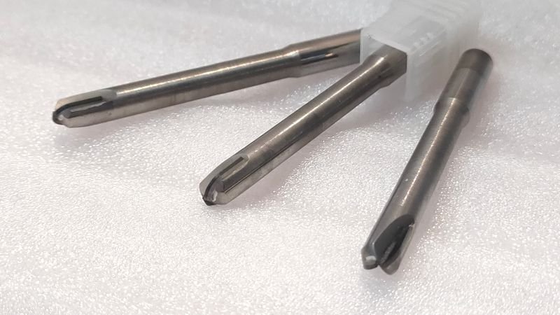
Selecting Appropriate End Mill Geometry (End Shape, Helix Angle, Edge Preparation)
Beyond the number of flutes, the specific shape or “geometry” of the end mill’s cutting portion plays a critical role in how it interacts with the aluminum workpiece. Key aspects include:
- End Shape (Tip Geometry):
- Square/Flat End: The standard workhorse for creating flat surfaces, pockets, and slots.
- Corner Radius: A square end with slightly rounded corners. This strengthens the corner, making it less prone to chipping, especially in demanding cuts. It also leaves a small radius where walls meet floors.
- Ball Nose3: A fully rounded tip used for machining 3D contoured surfaces, molds, and complex shapes.
- Helix Angle: This refers to the angle of the spiral flutes. For aluminum, higher helix angles (often in the range of 35° to 45°, though specific angles vary by manufacturer) are generally preferred. A higher helix promotes a smoother, shearing cutting action and helps to efficiently lift chips up and away from the cutting zone.
- Edge Preparation: How is the cutting edge finished? For aluminum, PCD edges are typically prepared to be very sharp with minimal rounding (a small hone or none at all). This sharp edge shears the relatively soft aluminum cleanly, minimizing cutting forces and reducing the tendency for material to stick to the edge (which can lead to Built-Up Edge, discussed later).
Selecting the right geometry involves matching these features to the specific type of milling operation you are performing – profiling, pocketing, finishing, contouring, etc.
Evaluating Shank Material and Ensuring Overall End Mill Rigidity
While the PCD cutting edges do the work, the non-cutting body of the tool, the shank, plays a vital support role. Rigidity – the tool’s resistance to bending or vibrating under cutting forces – is extremely important, especially with PCD which is hard but also brittle.
- Why Rigidity Matters: Imagine trying to write clearly with a pen that bends easily – the result won’t be precise. Similarly, if an end mill flexes or vibrates during cutting, it leads to inaccurate dimensions, poor surface finish, and can cause the delicate PCD edge to chip or break prematurely.
- Shank Material: To provide the necessary stiffness and support, high-performance PCD end mills almost universally use a solid carbide shank. Carbide is significantly stiffer than steel, providing a stable platform for the PCD cutting tip, particularly important for longer tools (higher overhang).
- Overall Consideration: When selecting a PCD end mill, consider its overall construction. Ensure the shank diameter and length are appropriate for the required cut depth and reach, providing maximum possible rigidity to prevent harmful vibrations.
Standard vs. Custom PCD End Mills: Making the Right Choice
Finally, you’ll need to decide whether a standard, off-the-shelf PCD end mill will suffice, or if a custom-designed tool is necessary.
- Standard PCD End Mills: Tool manufacturers offer a wide array of standard PCD end mills in common diameters, lengths, flute counts, and basic geometries. These tools are designed to handle a broad range of typical aluminum machining tasks effectively. They benefit from generally lower costs and immediate availability.
- Custom PCD End Mills: Sometimes, however, a standard tool isn’t the optimal solution. You might need a custom tool designed specifically for your application if:
- You need to create a unique profile or form on the workpiece.
- You want to combine multiple operations (e.g., milling and chamfering) into a single tool to save cycle time.
- Your application requires an unusual diameter, extra-long reach, or specific geometric features not found in standard offerings.
- You are running extremely high-volume production of a specific part, where even small optimizations in a custom tool design can lead to significant long-term savings.
Recommendation: Always evaluate standard PCD end mill options first. If your requirements are straightforward, a standard tool is likely the most economical choice. However, if your application is highly specialized or you see a clear opportunity for significant efficiency gains, discussing a custom PCD end mill solution with your tooling supplier is a worthwhile step. Be prepared for higher initial costs and longer lead times for custom tools.


What Are the Best Practices for Running PCD End Mills Effectively in Aluminum?
Okay, you’ve selected your PCD end mill – now, what are the key things you need to do to run it successfully on aluminum?
Establishing Starting Points for End Mill Speeds and Feeds (and How to Optimize)
Getting the “speeds and feeds” right is fundamental for any machining, and it’s especially important for PCD. Simply put:
- Speed (RPM): How fast the tool spins (Revolutions Per Minute).
- Feed (Feed Rate): How quickly it moves through the aluminum (e.g., inches per minute or mm per minute).
Where do you start?
- Start with Supplier Recommendations: This is the most important first step. Always begin with the cutting speed (often given in Surface Feet per Minute – SFM or meters per minute – m/min) and chip load (feed per tooth) recommendations provided by the manufacturer of your specific PCD end mill. They have tested their tools and can give you the best starting point for your specific tool and aluminum type. Remember that optimal parameters can vary significantly, so treat supplier data as a starting point for your specific conditions.
- Understand PCD’s Potential: Keep in mind, PCD typically allows for much higher cutting speeds in aluminum compared to standard carbide tools. Don’t be afraid to push the speed, within recommendations.
- Optimize Through Observation: These starting points are just that – starting points. Think of it like a cooking recipe: you start with the suggested time and temperature, but you might adjust based on your specific oven or how well-done you like your food. Similarly, you’ll need to fine-tune speeds and feeds based on:
- Your specific machine’s capabilities and condition.
- How rigidly the tool and workpiece are held.
- The exact aluminum alloy batch.
- The sound of the cut (smooth humming is usually good; loud screeching is bad).
- The resulting surface finish and part accuracy.
- Your goal (maximum speed vs. longest possible tool life).
Optimize carefully, making small adjustments and observing the results.
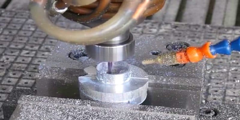
Implementing Effective Coolant Strategies for PCD End Milling
Next, how do you manage heat and chips during the cut? Coolant (or cutting fluid) typically helps with cooling the tool and part, lubricating the cut, and washing away chips. Interestingly, PCD handles heat quite well. This means sometimes you can use less coolant, or even none at all, compared to other tool materials when machining aluminum. Common Options:
- Flood Coolant: The traditional approach, using a large flow of liquid coolant. It provides excellent cooling and chip flushing and is very reliable. However, it can be messy, costly (fluid purchase and disposal), and requires machine enclosures.
- Minimum Quantity Lubrication (MQL): Uses a very small amount of oil mixed with compressed air, sprayed as a mist. It’s much cleaner, uses far less fluid (better for environment and cost), and often works very well with PCD’s heat handling, particularly in automotive and aerospace applications. Requires a reliable MQL system on the machine.
- Dry Machining (or Air Blast): Cutting with no liquid coolant, perhaps using an air blast to clear chips. This is sometimes possible with PCD in aluminum due to their properties. The big risks are chips welding to the tool or excessive heat buildup in the part, potentially affecting its dimensions or properties. Excellent chip evacuation is essential if attempting this.
The best strategy depends on your machine’s capabilities, the specific aluminum alloy, the type of cut, shop preferences, and environmental regulations. If considering MQL or dry machining, consult with your tooling supplier and machine tool builder.
The Critical Role of Tool Holding and Machine Tool Stability for End Mills
Remember how we mentioned PCD is hard but brittle? This makes how you hold the tool incredibly important. Any tiny wobble or vibration at the tool holder gets magnified at the cutting edge. For a brittle material like PCD, these vibrations can easily cause the edge to chip or fracture, drastically shortening tool life. Think of a tiny crack in glass – a small vibration can make it spread quickly. Recommendations:
- Use High-Quality Holders: Invest in precise, rigid tool holders designed for high-speed machining. Options like hydraulic chucks, high-precision collet chucks, or shrink-fit holders are often recommended as they grip the shank securely and minimize runout (wobble).
- Ensure Balance: For the high speeds PCD allows, ensure the tool and holder assembly are properly balanced to prevent vibration.
- Keep it Clean: Make sure the tool shank and the inside of the holder are perfectly clean before clamping. Dirt or debris can cause poor clamping and runout.
- Machine Stability: Even the best holder won’t help if the machine tool itself is loose or vibrates. A well-maintained, rigid machine tool is essential for realizing the benefits of PCD. Think of it like needing a solid workbench to do precise work – a shaky table makes everything harder. The aim is a rock-solid connection from the machine spindle right to the cutting edge.
End Mill Tool Path Strategies to Maximize Performance and Tool Life
How you program the tool to move through the material – the ‘tool path’ – also significantly impacts PCD end mill performance and life. Smoothness is Key. Because PCD is brittle, sudden impacts or sharp changes in cutting force can be damaging. Program tool paths that are as smooth as possible:
- Smooth Entries and Exits: Avoid plunging straight into the material or making abrupt 90-degree turns into a cut. Use “ramping,” “helical interpolation,” or “arc-in/roll-in” techniques where the tool enters the material gradually. Similarly, exit the cut smoothly.
- Consistent Chip Load: Try to maintain a steady amount of material being removed by each flute (chip load). Some advanced CAM strategies help with this.
- Avoid Sharp Corners: When milling pockets, use tool paths that create rounded corners internally instead of sharp ones, which can overload the tool.
- Consider Advanced Paths: For deep slots or heavy material removal, techniques like trochoidal milling (using circular, peeling paths) can help control the tool’s engagement angle, reduce cutting forces, improve chip evacuation, and extend tool life compared to just plowing straight through.
Think like a smooth driver, not an aggressive one – gentle entries, steady cutting, and smooth exits protect the tool.
Essential Handling, Storage, and Care for Fragile PCD End Mills
Finally, protecting your investment extends to how you handle the tool when it’s not in the machine. Treat PCD end mills like expensive, precise instruments – because they are! They are strong in cutting but vulnerable to impact. Practical Tips:
- Protective Packaging: Keep the end mill in its original protective case or tube until the moment you need to put it in the holder.
- Avoid Impacts: Never drop a PCD tool or allow it to bang against other tools, vices, or hard surfaces. Even a seemingly minor impact can cause microscopic damage that leads to failure during cutting.
- Careful Installation/Removal: Be gentle when inserting the end mill into the tool holder and when tightening the holder.
- Inspection: Visually inspect the cutting edges before and after use (magnification helps) for any signs of chipping or damage.
- Proper Storage: Store used tools carefully in appropriate containers, separated from other tools, to prevent edge damage.
Handle them like delicate glassware – they perform beautifully but require care to avoid breakage.
How Can You Troubleshoot Common Issues During PCD End Mill Application?
Even with best practices, what common problems might pop up when using PCD end mills on aluminum, and how can you fix them?
Addressing Premature End Mill Edge Chipping or Fracture in Use
Because PCD is very hard but also brittle, sometimes the cutting edge might chip or break unexpectedly. What should you check if this happens? Here’s a checklist:
- Impact Damage: Could the tool have been dropped or bumped before or during setup?
- Action: Inspect the tool very carefully (use magnification if possible). If damaged, it needs replacement. Review handling procedures.
- Lack of Rigidity / Vibration: Is there any looseness or vibration in the setup?
- Action: Double-check the tool holder, workpiece clamping, and overall machine stability. Address any source of vibration.
- Cutting Parameters Too Aggressive: Were the feed rate, depth of cut, or width of cut too high?
- Action: Reduce the parameter that seems too high. Re-consult supplier starting recommendations.
- Tool Path Problems: Did the tool slam into the part or make a sudden sharp turn under load?
- Action: Review the CAM program for smooth entries, exits, and transitions.
- Application Mismatch: Was the selected PCD grade or tool geometry suitable for the cut (e.g., heavy interruption)?
- Action: Re-evaluate the tool selection criteria for this specific task.
Finding the cause is like detective work – investigate handling, setup, workload, and the tool path.
- Action: Re-evaluate the tool selection criteria for this specific task.
Practical Steps to Manage and Prevent Built-Up Edge (BUE) on End Mills
Another common issue, especially with softer aluminum alloys, is “Built-Up Edge” or BUE. This is when small particles of aluminum literally weld themselves onto the cutting edge. This stuck material changes the tool’s shape, leading to poor surface finish, increased cutting forces, and it can even rip off, taking a piece of the PCD edge with it. Here’s how to manage and prevent BUE:
- Optimize Coolant/Lubrication: Is there enough clean cutting fluid reaching the edge?
- Action: Increase flow/pressure. Ensure nozzles are aimed correctly. If using MQL, verify proper atomization and delivery. Sometimes a different coolant type helps.
- Increase Cutting Speed: Often, BUE happens when cutting speeds are too low.
- Action: Gradually increase the cutting speed (RPM or SFM), staying within the recommended range. Higher speeds often reduce the tendency for material adhesion.
- Ensure Sharp Edges: A perfectly sharp, clean cutting edge is less prone to material sticking.
- Action: Inspect the PCD edge closely. Replace tools that show significant wear or BUE damage. Ensure the correct (usually very sharp) edge prep was used.
- Adjust Tool Path/Chip Thinning: Are chips getting too thin in parts of the cut?
- Action: Adjust tool paths to maintain a more consistent chip thickness.
Diagnosing and Correcting Unsatisfactory Surface Finish from End Mills
What if the machined aluminum surface just doesn’t look smooth enough? Here’s a systematic approach:
- Inspect the Cutting Edge: This is often the primary culprit.
- Action: Carefully check the PCD end mill for chipping, wear, or BUE. Replace the tool or address BUE if needed.
- Check for Vibration or Chatter: Are there wavy patterns or marks indicating shaking?
- Action: Address the vibration source (see next section).
- Review Cutting Parameters: Is the feed rate too high per tooth?
- Action: Try reducing the feed rate first. Ensure speed isn’t causing other issues like BUE.
- Assess Coolant and Chip Evacuation: Are chips being effectively flushed away?
- Action: Optimize coolant delivery. Trapped chips can mar the surface.
- Verify Tool Geometry: Does the end mill have the right geometry for finishing?
- Action: Confirm the selected tool matches the finishing requirement.
Start by checking the tool, then parameters, then setup stability.
Mitigating Vibration and Chatter During End Milling: Setup and Parameter Adjustments
That shaking or high-pitched squealing sound during cutting? That’s vibration or ‘chatter’, and it’s bad news. It leads to poor surface finish, noise, and tool damage. Addressing it involves looking at both the setup and the cutting process:
- Improve System Rigidity (Most Common Cause):
- Action: Use the shortest possible tool overhang. Employ high-quality, rigid tool holders. Ensure the workpiece is securely fixtured. Assess machine condition.
- Adjust Cutting Parameters:
- Action: Reduce the depth or width of cut. Vary the spindle speed (RPM) slightly (often 5-10% up or down) – this can disrupt the resonant frequency causing the chatter. Adjust feed rate accordingly.
- Check Tool Geometry (Less common fix):
- Action: If parameters and rigidity are optimized, consider if a different tool geometry might be inherently more stable for that cut.
Think of it like tuning a musical instrument – small adjustments can eliminate unwanted vibrations.
Recognizing Wear and Determining End-of-Life for PCD End Mills
Even PCD end mills wear out eventually. It’s important to distinguish normal wear from premature failure and know when to replace the tool.
- Normal Wear vs. Damage: Normal wear typically appears as a gradual rounding or a small, consistent flat area on the flank (side) of the cutting edge (flank wear land). This differs from distinct chips or fractures.
- Indicators of Normal End-of-Life:
- Part Quality Declines: Surface finish worsens, dimensions drift out of tolerance.
- Increased Power/Load: Machine works harder for the same cut.
- Audible Changes: Cut sounds duller or rougher.
- Measured Flank Wear: A noticeable wear land appears. The acceptable size varies greatly (consult your supplier or establish internal standards based on performance, but common ranges might be roughly 0.005″ to 0.015″ or 0.1 mm to 0.4 mm). Consistent monitoring helps predict tool life.
Recommendation: Implement a proactive tool change strategy based on performance, measured wear, or part count/time. Don’t run tools until catastrophic failure. This ensures process stability.
Conclusion
Successfully applying PCD end mills in aluminum requires more than just knowing their benefits. By carefully selecting the right tool based on the specific alloy and application, diligently applying best practices for setup, parameters, and tool care during operation, and methodically troubleshooting any issues that arise, you can truly unlock the performance potential of PCD. This integrated, practical approach ensures efficiency, high-quality results, and maximum value from your advanced tooling investment.
References
- significant advantages1 – ZYDiamondTools blog post discussing the benefits of using PCD tooling specifically for aluminum.
- automotive manufacturing for components such as engine blocks or pistons2 – ZYDiamondTools article on the specific application of PCD tools in processing automotive pistons.
- Ball Nose3 – ZYDiamondTools blog post providing detailed information specifically about PCD ball nose end mills.

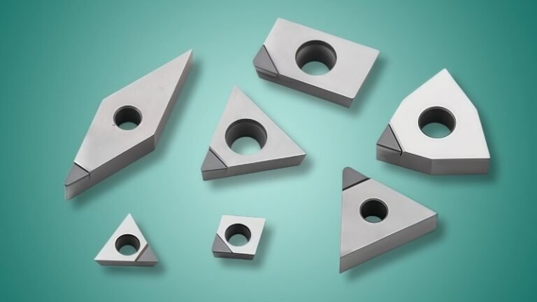
Which Turning Insert Shape Should You Choose?
Master turning insert selection. Our guide covers choosing the right shape for your job, decoding ISO codes, and selecting the
How Do You Solve Vibration, Chip Control, and Surface Finish Issues in PCD Grooving?
Solve common PCD grooving problems. This guide details how to fix vibration, improve chip evacuation, and achieve a flawless sidewall
Why Is Your Tooling Wearing Out Prematurely? A Machinist’s Guide to Key Causes & Proven Solutions
Facing premature tool wear? Learn the key causes like heat, vibration, & wrong parameters. Discover proven solutions from setup to
How Do You Select the Optimal PCD Tools for Scroll Compressor Machining?
Learn how to select the right PCD tools for scroll compressor machining. This guide covers the benefits over carbide, key
