-
Whatsapp: +86 13526572721
-
Email: info@zydiamondtools.com
-
Address: AUX Industrial Park, Zhengzhou City, Henan Province, China
-
Whatsapp: +86 13526572721
-
Email: info@zydiamondtools.com
-
Address: AUX Industrial Park, Zhengzhou City, Henan Province, China

A Comprehensive Guide to PCD Router Tooling: Selection, Programming, and Maintenance
Switching to PCD (Polycrystalline Diamond) router tooling1 is a strategic investment for high-volume shops processing abrasive materials like MDF, carbon fiber, and laminates. While the initial cost is significantly higher than carbide, PCD often delivers 25 to 50 times the lifespan of solid carbide2. However, realizing this return on investment requires precise machine calibration, specific programming strategies to avoid brittle fracture, and strict maintenance protocols to protect the diamond cutting edges from impact and heat.
Choosing the Correct PCD Profile for Specific Routing Applications
Selecting the correct PCD profile depends entirely on your material properties and required edge quality. For high-speed panel processing, use segmented nesting bits designed for rapid chip evacuation. When cutting double-sided laminates or melamine, select compression geometries to prevent surface chipping. For decorative edges or joinery, utilize profiling tools with custom-ground diamond tips.
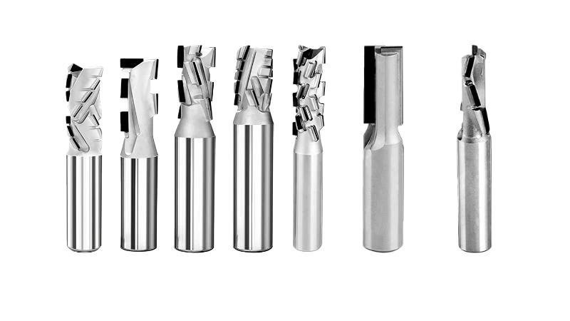
Nesting Bits for High Volume MDF and Particleboard Sheets
In high-production environments, the goal is maximizing sheet throughput. Nesting bits are the workhorses for this task, specifically designed to handle the abrasive nature of MDF (Medium Density Fiberboard)3 and particleboard.
Unlike standard solid carbide bits, PCD nesting bits often feature a segmented design. This means the diamond tips are arranged in a spiral pattern around the tool body rather than a single continuous flute.
Segmented vs. Continuous Tips
The tip arrangement functions similarly to a roughing end mill in metalworking compared to a finishing mill. Just as a roughing mill has serrations to break metal chips into smaller pieces to reduce load, a segmented PCD bit breaks wood chips into smaller dust particles.
- Chip Evacuation: Smaller dust particles are easier for vacuum extraction systems to remove from the kerf, keeping the cut cooler.
- Reduced Resistance: Breaking the cut into segments reduces the radial cutting pressure on the spindle.
However, some applications require a continuous cutting edge. Here is a breakdown to help you choose:
| Feature | Segmented Helix Design | Continuous Straight Edge |
|---|---|---|
| Primary Use | High-speed nesting of raw MDF/Particleboard | Grooving, jointing, or slow-speed sizing |
| Chip Style | Small dust/chips (Optimized extraction) | Long strips or larger chips |
| Noise Level | Quieter (Breaks air resistance) | Louder (Higher windage noise) |
| Edge Finish | Good (May show faint feed lines) | Excellent (Glass-smooth finish) |
Pro Tip: If you are nesting raw board that will be edge-banded later, the slight feed lines from a segmented bit are irrelevant. Prioritize the speed and extended lifespan of the segmented geometry.
Compression Geometries for Chip Free Melamine and Laminate Cutting
Cutting laminated materials presents a unique challenge: preventing chipping on both faces. A standard up-cut bit pulls the top layer up, causing chips, while a down-cut bit pushes the bottom layer down, causing “blowout.”
Compression bits solve this by combining two geometries on a single shank. The tip features an up-shear angle, while the top of the cutting length features a down-shear angle.
How It Works
When the bit engages the material, the cutting forces are directed toward the center of the board.
- Bottom of the sheet: The up-shear pulls chips inward, supporting the bottom veneer for a clean cut.
- Top of the sheet: The down-shear pushes chips inward, ensuring the top veneer remains intact.
This geometry is essential for:
- Melamine coated particleboard.
- High-Pressure Laminate (HPL)4.
- Double-sided plywood veneers.
The Importance of the “Mortise” Length
A critical specification is the length of the up-cut section, known as the mortise compression length. To function correctly, the up-cut portion must be shorter than the material thickness.
- Example: When cutting 3/4″ material, the up-cut portion should typically be around .200″ to .500″. If the up-cut is too long, it will rise above the board surface, losing the compression effect on the top edge.
Note: Mortise lengths vary significantly between manufacturers. Verify the exact up-cut length to ensure it fits your thinnest sheet stock.
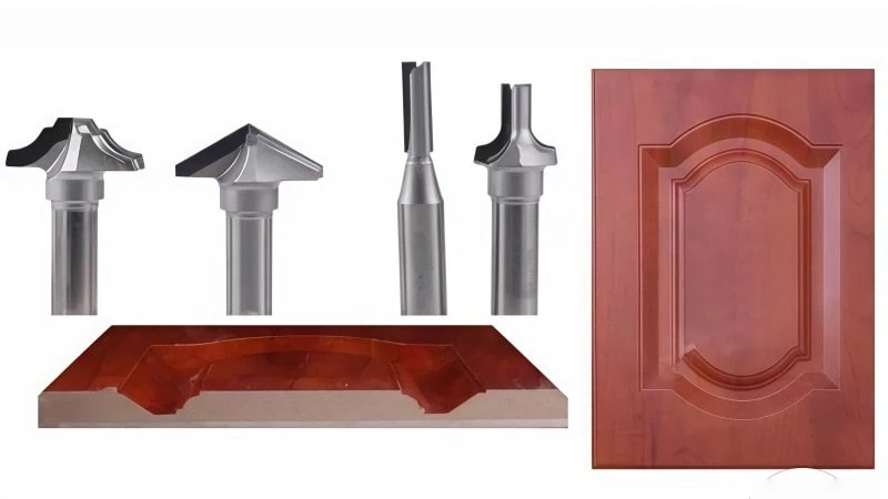
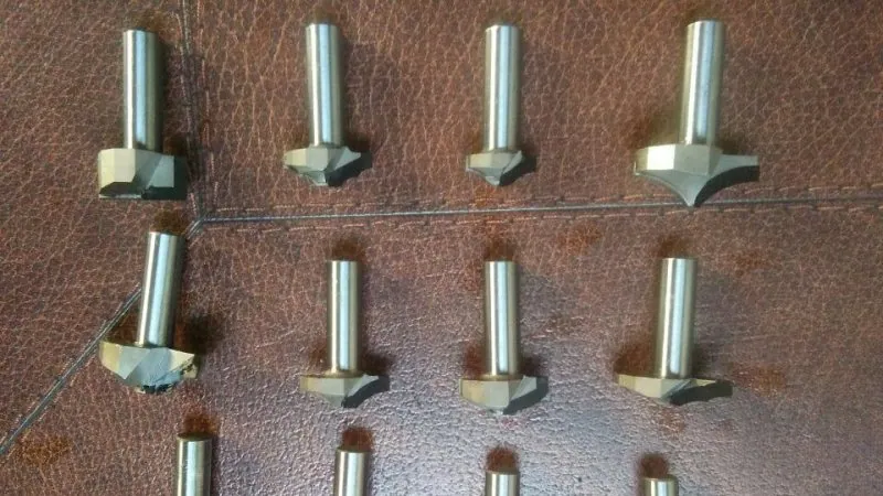
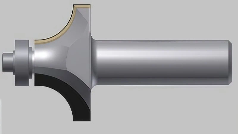
Profiling Tools for Custom Edge Shaping and Grooving
PCD profiling tools are custom-ground to match a specific “shadow graph” or profile, such as round-overs, ogees, or V-grooves for folding miter joints (common in Aluminum Composite Material/ACM processing).
Because PCD is extremely hard, it cannot be ground into sharp, tiny inner corners as easily as carbide. Therefore, when designing profiles for PCD tooling, engineers must account for a slight radius on internal corners.
Unlike a standard insert knife cutterhead used in a shaper machine, PCD router profiles are typically permanently brazed. This provides superior dynamic balance at the high RPMs (18,000+) used on CNC routers, resulting in a surface finish that often requires no sanding before finishing.
Essential Router Hardware Requirements for Diamond Tooling
To successfully run PCD tooling, a CNC router requires a rigid machine structure and a high-precision spindle with runout measuring less than 0.0004 inches (0.01mm). Operators must utilize ISO-balanced tool holders and pristine collets to eliminate vibration, as the extreme hardness of diamond makes it susceptible to micro-fracturing from even minor mechanical instability.
Impact of Spindle Runout and Collet Quality on Tool Life
PCD is the hardest material used in woodworking, but this hardness comes with extreme brittleness. Unlike carbide, which possesses some transverse rupture strength to absorb vibration, diamond tips will micro-fracture under impact. Therefore, runout5 (rotational inaccuracy) is critical.
Imagine a precision grinding wheel that is mounted off-center; it will hammer the workpiece rather than grind it. Similarly, if a PCD tool runs out, the diamond edge hammers the material.
The “0.0001 Inch” Rule
Industry data suggests that for every 0.0001 inches (2.5 microns) of runout, tool life can decrease by 10%. If your spindle has 0.001 inches of runout, you may lose 50% or more of the tool’s potential lifespan.
Note: Allowable runout tolerances can vary based on the tool diameter. Always consult the spindle manual for specific runout limits.
The Role of the Collet
The collet is often the primary source of runout.
- Dust Contamination: A single speck of sawdust inside a collet can offset the tool by several thousandths of an inch.
- Fatigue: Collets are consumables. Over time, the metal fatigues and loses its ability to grip the tool shank concentrically.
Pro Tip: Replace collets every 400-600 hours of runtime when using PCD tooling. This is a cost-effective preventive measure for expensive diamond bits.
Selecting Tool Holders for High Speed Balance
At speeds of 18,000 to 24,000 RPM, any imbalance in the tool holder creates centrifugal force that translates into vibration. For PCD tools, vibration causes micro-chipping along the cutting edge.
Comparing Holder Types for PCD
Choose a system that offers both high gripping force and concentricity.
| Holder Type | Grip Strength | Runout Accuracy | Suitability for PCD |
|---|---|---|---|
| Standard ER Collet | Moderate | Good (0.0004″ – 0.0008″) | Acceptable for general nesting |
| High-Precision ER | High | Very Good (<0.0002″) | Recommended for most shops |
| Heat Shrink | Very High | Excellent (<0.0001″) | Ideal for aerospace6/high-volume |
| Hydraulic Chuck | High | Excellent (<0.0001″) | Ideal for finishing cuts |
The Importance of Balancing
Ensure tool holders are balanced to G2.5 specifications at your operating RPM. Using an unbalanced holder is akin to running an unbalanced grinding wheel; the faster it spins, the more the centrifugal force amplifies the vibration amplitude, transmitting shock directly to the brittle diamond tip.
Vacuum Hold Down Stability Requirements to Prevent Vibration
Even with a perfect spindle and balanced holder, tools will fail if the workpiece moves. Vacuum hold down rigidity is non-negotiable for PCD.
The “Vibration Loop”
If a sheet of melamine or plywood lifts slightly or vibrates during the cut:
- The material vibrates up into the spinning cutter.
- The hard diamond edge impacts the material surface irregularly.
- The cutting edge chips, or the tool snaps at the shank.
Key Vacuum System Metrics
- Vacuum Flow (CFM): High airflow is required to compensate for leakage through the spoilboard.
- Vacuum Pressure (Hg): Sufficient pressure is needed to clamp smaller parts against lateral forces.
If you are cutting small parts prone to shifting, address this before switching to PCD. Consider using gasketing tape or leaving an “onion skin” (thin layer of material) at the bottom of the cut to maintain a vacuum seal before the final pass.
Programming Toolpaths and Parameters for PCD Performance
To optimize PCD performance, operators must calculate a chip load that evacuates heat through the waste material rather than absorbing it into the tool body. Furthermore, programming must utilize ramp or helical entry strategies instead of vertical plunging to eliminate impact stress, while feed rates should be adjusted dynamically to match the varying densities of composite materials.
Calculating Chip Load to Manage Heat Generation
Heat is the primary enemy of the brazing alloy that holds the diamond tip to the carbide body. The most effective way to manage heat is to transfer it into the chip.
If the chip is thick enough, it carries the heat away. If the chip is too thin (dust), the tool rubs against the material, generating intense friction and heat.
The Chip Load Formula
You must calculate Chip Load: the thickness of the material removed by each cutting edge during one revolution.
Formula: Feed Rate (IPM) ÷ (RPM × Number of Flutes) = Chip Load
For example, running a 2-flute PCD compression bit at 18,000 RPM with a target chip load of 0.015” (common for 3/4” particleboard):
- RPM: 18,000
- Flutes: 2
- Target Chip Load: 0.015”
- Calculation: 18,000 × 2 × 0.015 = 540 Inches Per Minute (IPM)
You can verify these calculations using a digital speeds & feeds calculator7 to ensure accuracy. Running this tool at only 200 IPM reduces the chip load to 0.005”, causing rubbing, burning, and rapid dulling.
| Parameter | Effect on Tool | Result |
|---|---|---|
| Chip Load Too Low | Rubbing / Friction | Heat buildup, burnt edges, premature dulling |
| Chip Load Optimal | Clean Cutting | Heat leaves with chips, extended tool life |
| Chip Load Too High | High Mechanical Force | Potential tool breakage or spindle stalling |
Ramping Strategies to Avoid Vertical Plunge Stress
Standard carbide router bits can often handle a direct vertical plunge. PCD router bits generally cannot. The geometry often leaves the center of the bottom tip without a cutting edge, or the diamond there is highly susceptible to impact. Plunging vertically places axial pressure on the most fragile part of the tool.
Preferred Entry Methods
- Linear Ramping:
The tool moves forward while descending. This engages the diamond cutting edge gradually along the side profile, similar to a thread milling entry, rather than shocking the tip with axial force.- Recommended Angle: Typically 3° to 5°.
- Helical Interpolation:
The tool moves in a circular, corkscrew motion as it descends.- Application: Ideal for cutting holes or pockets where linear ramping space is limited.
- Benefit: Keeps the tool in constant motion and aids in chip evacuation.
Never use a “Plunge” entry setting in CAM software with PCD tooling unless the tool is specifically engineered with a plunging diamond tip.
Adjusting Feed Rates for Density Variations in Composite Panels
Composite materials like particleboard have varying densities. The face (skin) is hard and dense due to resin compression, while the core is softer.
If running at a constant feed rate, the tool experiences a “shock” when engaging the hard skin.
The “Onion Skin” Approach
When cutting small parts, operators often leave a thin layer (onion skin) to hold the part. This skin consists entirely of the hard, dense bottom face.
- Full Depth Cut: The tool cuts both hard skin and soft core; the core stabilizes the cut.
- Skin Only Cut: The tool engages only the high-density resin layer, which can cause chatter.
Strategy: Reduce feed rates by 10-20% when performing final pass-through cuts on the bottom skin. This ensures the diamond edge slices cleanly through the dense resin without vibration.
Protecting Your Investment Through Proper Handling and Care
To maximize the lifespan of PCD router tooling, operators must regularly remove pitch and resin buildup using non-caustic solvents to prevent heat-generating friction. Tools should be stored individually in protective sleeves or dedicated racks to avoid carbide-on-diamond contact, while wear patterns must be monitored under magnification to identify micro-chipping before it leads to catastrophic failure.
Cleaning Pitch and Resin Buildup without Damaging Edges
Resin is a silent killer. Heat turns wood sap and glue into a sticky pitch that fuses to the router bit. This coating covers the diamond edge, causing friction instead of cutting. This heat can degrade the brazing alloy8, causing the diamond tip to detach.
The Safe Cleaning Process
- Chemical Selection: Never use caustic oven cleaners or strong acids, as they attack the brazing alloy. Use a specialized resin remover or citrus-based solvent.
- Soaking: Allow the tool to soak for 10-15 minutes.
- Mechanical Cleaning: Use a nylon bristle brush. Never use a wire brush or knife. A steel wire brush can micro-fracture the brittle diamond edge.
| Cleaning Method | Safety for PCD | Result |
|---|---|---|
| Wire Brush | ❌ Unsafe | Micro-fractures the cutting edge |
| Oven Cleaner | ❌ Unsafe | Dissolves the silver solder/braze |
| Nylon Brush + Solvent | ✅ Safe | Removes pitch without damage |
| Ultrasonic Cleaner | ✅ Safe | Deep cleans without contact |
Storage Protocols to Prevent Brittle Fracture During Downtime
PCD shares similar brittle characteristics with ceramic turning inserts; it possesses immense compressive strength but very low transverse rupture strength. Most PCD damage occurs off the machine—often when an operator tosses the bit into a drawer or tray.
If a steel wrench strikes a PCD bit, the diamond tip will likely flake off.
The “Micrometer” Standard
Treat PCD bits with the same care as precision micrometers.
- Individual Sleeves: Keep the bit in its original packaging when not in use.
- Spacing: In tool racks, ensure bits are spaced far enough apart that they cannot contact each other during handling.
- Protective Coating: For long-term storage, some shops dip the tip in a protective hot wax seal (similar to end mill shipping protection) to prevent accidental impact damage.
Monitoring Wear Patterns to Determine Replacement Timing
PCD does not dull like steel. Steel edges round over gradually, whereas PCD maintains its shape until it chips or wears a “land.” Running a tool past its useful life risks snapping the tool body due to increased cutting pressure.
Identifying the “White Line”
In melamine and laminate processing, the first sign of wear is often a faint white line along the cut edge of the material. This indicates the diamond is pushing the paper coating rather than shearing it cleanly.
Measuring Flank Wear
For a technical assessment, use a 10x magnifying loupe to inspect the flank (back side) of the cutting tip. Look for a flat, shiny spot known as the wear land.
- 0.010″ – 0.015″ (0.25mm – 0.4mm) Wear: Typical service limit. The tool is dulling but often still serviceable.
- >0.020″ (0.5mm) Wear: Cutting pressure is excessive. The tool is at high risk of failure.
Industry Insight: Catching wear early (at the 0.010″ mark) is crucial for serviceable tools. Once chips in the diamond edge are visible to the naked eye, the tool often requires excessive grinding to repair, potentially rendering it unserviceable.
Conclusion
Transitioning to PCD router tooling shifts production from a “consumable-heavy” model to a “high-performance” model. While the upfront cost is higher, the ability to maintain consistent cutting tolerances and reduce downtime offers an undeniable competitive advantage.
By selecting the correct geometry (nesting vs. compression), ensuring your router’s mechanical integrity (low runout), and programming for heat management (chip load), you unlock the full potential of diamond tooling. Treat these tools with precision, and they will become the most profitable assets in your CNC workflow.
References
- PCD (Polycrystalline Diamond) router tooling1 – ZYDiamondTools product page for high-performance PCD router bits.
- Solid Carbide2 – ZYDiamondTools blog post detailing the differences between PCD and Carbide tools.
- MDF (Medium Density Fiberboard)3 – Wikipedia article explaining the manufacturing and properties of MDF.
- High-Pressure Laminate (HPL)4 – Wikipedia article covering the types and uses of decorative laminates.
- Runout5 – Wikipedia technical explanation of mechanical run-out in rotating systems.
- Aerospace6 – ZYDiamondTools industry page for aerospace machining solutions.
- Speeds & Feeds Calculator7 – ZYDiamondTools utility page for calculating optimal cutting parameters.
- Brazing Alloy8 – ScienceDirect topic page covering brazing alloys used in tool manufacturing.


